Advances in Bioscience and Biotechnology
Vol.2 No.5(2011), Article ID:7834,5 pages DOI:10.4236/abb.2011.25053
Measuring surface geometry of adherent cells using oblique transillumination
![]()
1Department of Bioengineering and Robotics, Tohoku University, Sendai, Japan;
2Graduate School of Natural Science and Technology, Okayama University, Okayama, Japan.
E-mail: *deguchi@bml.mech.tohoku.ac.jp
Received 13 July 2011; revised 9 August 2011; accepted 8 September 2011.
Keywords: 3D Cell Morphology; Oblique Illumination; Rotating Stage; Microscopy
ABSTRACT
We present a new technique for estimating cell surface geometry. A dish supporting adherent cells is observed using oblique transillumination and rotated in the horizontal plane using a stepping motor. The stage rotation-dependent movements of the start and end points of a shadow formed behind the illuminated cells uniquely determine the relative height differences between points along the cell surface. Thus, using custom-made apparatuses and living endothelial cells, we demonstrate that the combination of a rotating stage and oblique lighting allows for the evaluation of three-dimensional surface geometry of adherent cells. As compared to confocal microscopy and atomic force microscopy, which are commonly used for measuring cell surface geometry, this approach can be performed rapidly and is especially suitable for the observation of unstained cells over a large surface covering multiple cells at a time.
1. INTRODUCTION
Cell morphology and its function are closely associated [1]. Therefore, observing the cell morphology is common in cellular biology. However, the height and slope in the z-direction (vertical direction) of cells adhering to a culture dish or plate via the extracellular matrix cannot be measured by ordinary optical and electron microscopy [2].
Typically, confocal microscopy and atomic force microscopy are used to observe the three-dimensional morphology of adherent cells [3-5]. Confocal microscopy is an optical imaging technique used to increase optical resolution by using a spatial pinhole to eliminate out-offocus light in cells that are thicker than the focal plane. It enables the reconstruction of three-dimensional structures of cells from multiple images, although it requires cell staining prior to observation. Atomic force microscopy uses a deflectable cantilever as a force sensor. Cell height is physically measured on the basis of the cantilever deflection, providing a three-dimensional surface geometry of adherent cells. However, the device requires substantial time—typically, several minutes—to scan a wide range of area that covers multiple cells.
Here we describe a simple, alternative technique using a rotating microscope stage to evaluate the threedimensional surface geometry of adherent cells. A dish supporting cultured cells observed using oblique lighting (similar to Mempel et al. [6]) was rotated using a motor. Because of the oblique lighting, the stage rotationdependent movements of the start and end points of a shadow behind the illuminated cells determine the relative height differences between points on the cell surface. Thus, the combination of oblique lighting and a rotating stage allows for the rapid evaluation of the cell surface geometry over a large surface covering multiple cells.
2. MATERIALS AND METHODS
2.1. Cell Preparation
Bovine aortic endothelial cells (Dainippon Sumitomo Pharma) were cultured in Dulbecco’s modified Eagle medium (Invitrogen) supplemented with 10% (v/v) fetal bovine serum (JRH Bioscience) and 1% each of penicillin and streptomycin (Invitrogen) in an incubator at 37˚C and 5% CO2/95% air. Cells were seeded in a 35 mm diameter plastic base culture dish.
2.2. Experimental Setup
A gear wheel (diameter = 125 mm; teeth number = 100) and pinion (diameter = 25 mm; teeth number = 20) were manufactured from S45C carbon steel (Figure 1). The base of the gear wheel was mounted onto the stage of an inverted microscope (IX70, Olympus). The gear wheel had a hole (diameter = 28 mm) at the center where a conventional cell culture dish (diameter = 35 mm) was
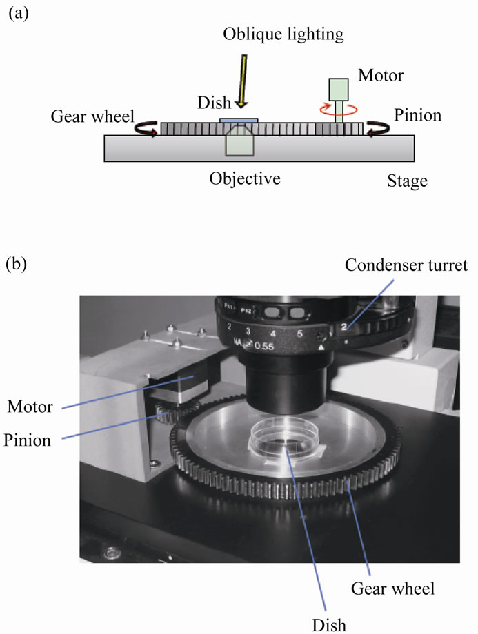
Figure 1. Experimental setup. (a) Schematic drawing of the side view of the system. (b) Image of the system.
physically fixed. The rotatable gear wheel was meshed with the pinion driven by a stepping motor (PK223PA, Oriental Motor) controlled by a program written in LabVIEW software (National Instruments). The rotation angle of the dish was controlled using this system.
2.3. Image Acquisition
Cells were originally observed by regular bright-field phase-contrast microscopy (halogen light through a green interference filter) using a 20× objective lens. Oblique transillumination was achieved by slightly displacing an annular ring in the condenser turret from the regular position for conventional phase-contrast microscopy within the horizontal plane. The combination of phase-contrast microscopy and oblique lighting allows for the detection of cells with a shadow turned to one particular direction. Images were taken by a CCD camera (DP70, Olympus) and a timelapse image-acquisition system (DPController, Olympus) during a 360˚ stage rotation. The observation was performed at room temperature.
2.4. Image Analysis
As a performance evaluation, images taken at 45˚ intervals were used for the following image analysis, and 8 total images (8 × 45˚ = 360˚) were analyzed using the computer software (Vision, National Instruments). Firstthe center of the photographed field was determined from the circular trajectory due to the rotation. The accurate planar angle of oblique lighting was then determined for each cell of interest. Images were rotated employing Vision, yielding sequential images of cells illuminated from different angles. For each cell, a planar square field large enough to cover the entire area of the cell was divided into 36 (= 6 × 6) square subfields. The intensity at each subfield corner was measured by Vision to distinguish the boundary of the shadows behind the illuminated cell. A comparison of the start and end points of the shadow at each angle uniquely determined the relative height between the points, thus providing the surface geometry. Here shadow and intracellular materials can be distinguished because only the shadow rotates together with the illumination angle, whereas intracellular materials are fixed within cells for short observation times of several tens of seconds. Images were unaltered except for rotation and contrast enhancement.
3. RESULTS
A shadow with enhanced contrast was created by slightly displacing the condenser annulus within the horizontal plane. The shadowing effect from the resultant oblique lighting provided cell images similar in appearance to those taken by differential interference contrast (DIC) microscopy and reflected light oblique transillumination microscopy [6] (Figure 2). The pinion was slowly rotated
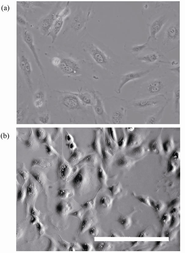
Figure 2. Images of endothelial cells. (a) Cells viewed by phase-contrast microscopy. (b) Cells viewed by the present oblique transillumination. Scale bar: 200 µm.
within the horizontal plane from 0˚ to 360˚ using the stepping motor by rotating the gear wheel in the opposite direction. The dish fixed on the gear wheel was rotated as well while cell images were acquired (Figure 3). After measuring the center of the circular trajectory from the acquired images, the accurate planar angle of oblique illumination was determined from the trajectory center. The individual images were then rotated using Vision considering the calibrated illumination angles. As a result, sequential images with cells illuminated from different angles were obtained (Figures 4 and 5). The image analysis was performed to uniquely determine the relative heights between arbitrary points along the cell surface from the shadows behind cells created by the oblique illumination. The consequent relative heights were visualized using AVese software, yielding the surface geometry of cells (Figure 6). The highest and lowest points in the image were defined to be 1 and 0, respectively.
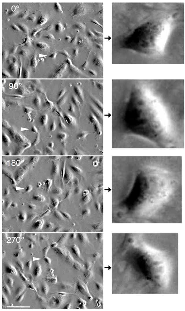
Figure 3. Effect of stage rotation on cell appearance. The images obtained at rotation angles of 0˚, 90˚, 180˚, and 270˚ are shown. The arrowheads show one identical cell, which is shown in magnified images on the right. Note that the cell shadow extends in a fixed leftward direction, although this cell is rotated in the horizontal plane. Scale bar: 100 µm.
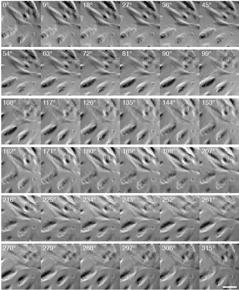
Figure 4. Cells illuminated from different angles. In raw images, the shadow angle (or illumination angle) is fixed, while cells are rotated in the horizontal plane, as shown in Figure 3. The image analysis converts these raw images to processed images in which cells are fixed, while the illumination angle is rotated around the cells of interest. Scale bar: 50 µm.
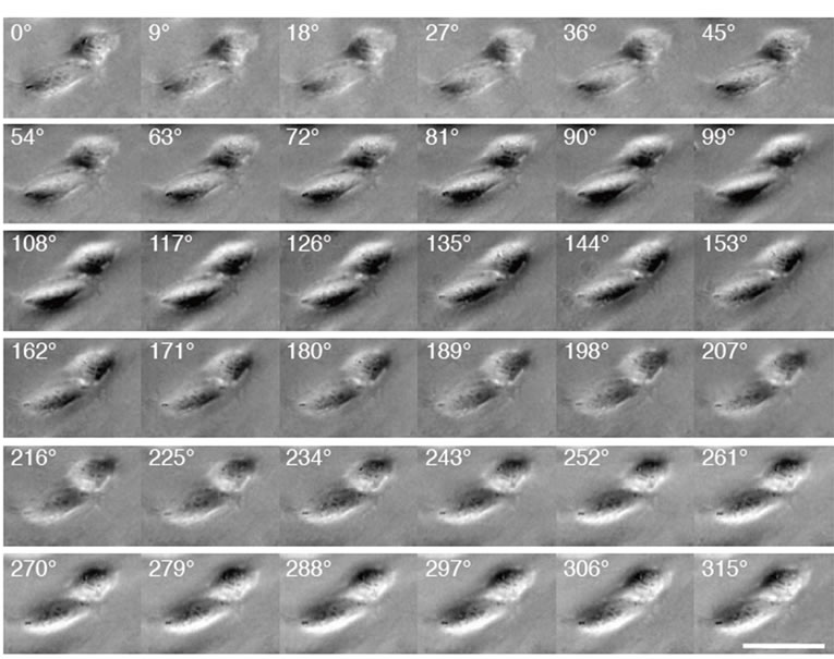
Figure 5. Another example of sequential images of cells illuminated from different angles. Scale bar: 50 µm.
4. DISCUSSION
Phase-contrast microscopy is a common technique in which small phase shifts in the light passing through transparent cells are converted into contrast changes in the image. In this system, the condenser annulus is cen-
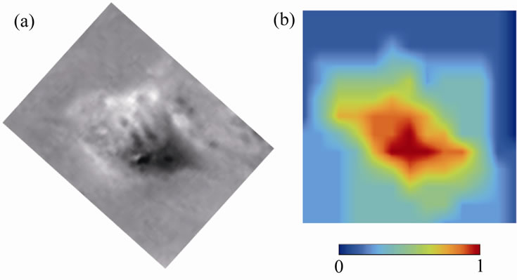
Figure 6. Surface geometry of a cell obtained after the image analysis. (a) An original image of the cell illuminated from one particular angle. (b) Evaluated surface geometry of the corresponding cell. Relative cell height at each measured point is shown in color.
tered with respect to the matching objective phase plate. Here by slightly displacing the condenser annular ring within the horizontal plane, we obtained cell images with an enhanced contrast shadow titled to one particular direction, similar to those obtained by reflected light oblique transillumination microscopy [6] (Figure 2). By tracking the shadow of cells subject to horizontal rotations using a motor (Figures 3-5), we demonstrated that the surface geometry of the cells could be determined (Figure 6).
Confocal microscopy and atomic force microscopy are often used to measure cellular surface geometry [3-5]. While they are highly accurate, they have some limitations. Confocal microscopy requires fluorescent markers introduced or expressed in cells to acquire the images. Atomic force microscopy typically takes a long period of time—several minutes—to obtain such measurements. The present technique using oblique lighting and a rotating stage provides an alternative for estimating the surface geometry of unstained cells. With its semiautomatic image analysis, the evaluation of surface geometry of multiple cells is rapid, within tens of seconds for the steady stage rotation. Practically, this system is less expensive than confocal and atomic force microscopy because the surface geometry evaluation relies on subsequent image analysis after acquiring cell images under steady planar rotation of the stage.
The images obtained by the oblique lighting technique are also similar to those by DIC microscopy, which is widely used to enhance the contrast in unstained cells and observe planar morphology. However, DIC microscopy is not applicable to the observation of living cells in plastic culture dishes because of their birefringence. Thus, the combination of oblique lighting and phasecontrast microscopy may be more versatile and suitable for obtaining three-dimensional morphology of cells placed in any transparent material.
Rotation systems for cell structure observation have been reported by Matsumoto and colleagues [7-10] in which an individual cell is captured using a glass pipette and then rotated about the pipette’s axis to observe its three-dimensional structure. Sophisticated feedback controllers and fluorescence imagers are used in this system, which allow for the acquisition of highly accurate images. In contrast, the present system has no feedback controller and is equipped only with a stepping motor because the surface geometry evaluation relies on subsequent analysis of acquired images. The current system was developed to analyze the surface structure of multiple cells adherent to a flat (glass or plastic) plate. Thus, while our rotation system is unable to identify intracellular structures with high resolution, it is particularly well suited for collecting large amounts of data on epithelial structure and changes in adherent cell height induced by pharmacologic agents [4,5].
In conclusion, the present study proposed a technique for the easy estimation of the surface geometry of adherent cells. Living cell images were obtained by oblique transillumination, while the stage supporting the cells was rotated using a motor and a custom-made gear wheel and pinion. Changes in the shadow formed behind the cells were analyzed to evaluate relative height differences between points along the cell surface. Thus, the present system allows for the measurement of the surface geometry of adherent cells within a short time period over tens of seconds. Absolute values of the cell heights can be obtained with additional calibrations and here are expressed as relative values.
5. ACKNOWLEDGEMENTS
The authors thank Yoshihiko Tamura for his assistance in manufacturing the apparatus and Seiichi Washio and Satoshi Takahashi for helpful discussions. SD gratefully acknowledges the support from the Japan Science and Technology Agency. This work was partly supported by Grants-in-Aid for Scientific Research from the Japan Ministry of Education, Culture, Sports, Science, and Technology (#21680039 and #20001007).
REFERENCES
- Chen, C.S., Mrksich, M., Huang, S., Whitesides, G.M. and Ingber, D.E. (1997) Geometric control of cell life and death. Science, 276, 1425-1428. doi:10.1126/science.276.5317.1425
- Liu, S.Q., Yen, M. and Fung, Y.C. (1994) On measuring the third dimension of cultured endothelial cells in shear flow. Proceedings of the National Academy of Sciences of the United States of America, 91, 8782-8786. doi:10.1073/pnas.91.19.8782
- Haga, H., Sasaki, S., Kawabata, K., Ito, E., Ushiki, T., Abe, K. and Sambongi, T. (2000) Elasticity mapping of living fibroblasts by AFM and immunofluorescence observation of cytoskeleton. Ultramicroscopy, 82, 253-258. doi:10.1016/S0304-3991(99)00157-6
- Nagayama, K. and Matsumoto, T. (2008) Contribution of actin filaments and microtubules to quasi-in situ tensile properties and internal force balance of cultured smooth muscle cells on a substrate. American Journal of Physiology—Cell Physiology, 295, C1569-C1578. doi:10.1152/ajpcell.00098.2008
- Deguchi, S., Fukamachi, H., Hashimoto, K., Iio, K. and Tsujioka, K. (2009) Measurement and finite element modeling of the force balance in the vertical section of adhering vascular endothelial cells. Journal of the Mechanical Behavior of Biomedical Materials, 2, 173-185. doi:10.1016/j.jmbbm.2008.07.003
- Mempel, T.R., Moser, C., Hutter, J., Kuebler, W.M. and Krombach, F. (2003) Visualization of leukocyte transendothelial and interstitial migration using reflected light oblique transillumination in intravital video microscopy. Journal of Vascular Research, 40, 435-441. doi:10.1159/000073902
- Matsumoto, T., Tajima, H., Ito, N., Nagayama, K. and Sato, M. (2004) Development of a cell rotation system for the observation of 3D microstructure of cells. Proceedings of Workshop on Biomechanical Engineering and Biomaterials, WBEB2004-14.
- Matsumoto, T., Tajima, H., Ito, N., Nagayama, K. and Sato, M. (2005) A cell rotation system for the observation of 3D microstructure of cells. Proceedings of the 2005 Summer Bioengineering Conference, b0158837.
- Ogawa, M., Wake, F., Nagayama, K., Ishino, Y. and Matsumoto, T. (2006) 3-D observation of cell nucleus and cytoskeleton with cell rotation system. Proceedings of JSME Annual Meeting 2006, Sendai, 4-6 August 2006, 279-280.
- Matsumoto, T., Ogawa, M., Wake, F., Nagayama, K. and Ishino, Y. (2007) Three dimensional observation of cellular microstructures with a novel fluorescent optical tomography. Proceedings of 3rd Asian Pacific Conference on Biomechanics, Tokyo, 5-8 November 2007, S20.