Int'l J. of Communications, Network and System Sciences
Vol.2 No.4(2009), Article ID:543,7 pages DOI:10.4236/ijcns.2009.24034
Design and Implementation for Ladder Diagram in Hydropower Simulation System Based on All Paths Searching Algorithm
College of Information Science and Engineering, Northeastern University, Shenyang, China
Email: Libokkkkk_0_0_0@yahoo.com.cn, zhhai@neuera.com
Received August 13, 2008; revised November 18, 2008; accepted January 29, 2009
Keywords: Ladder Diagram, Object-oriented Thought, Undigraph
ABSTRACT
An approach to design and implement the control function of LD (Ladder Diagram) in the hydropower simulation system based on all paths searching algorithm is proposed in this paper. LD is widely used as a programming language for PLC (Programmable Logic Controller), but it doesn’t be executed automatically in the hydropower simulation system which is a software system, and there is no compiler or interpretation for LD in it. The approach in this paper is not only to present a graphical interface to design LD, but also implement its control function through trans-forming it to a corresponding undigraph, in which, all paths between two vertexes (live wire and null line) are searched by the proposed algorithm. An application example is presented to verify the validity of the algorithm and shows that the algorithm is correct and practicable. In addition, how to implement the control function based on object-oriented thought is introduced.The running time is shown at last, which proves that the system with the algorithm can meet the real-time request in the hydropower simulation system.
1. Introduction
Recently, great changes have arisen in the electrical virtual instruments, e.g. the hydropower simulation system [1–4]. It is a comprehensive system including hydraulic, water conservancy, mechanics and autocontrol. LD control system plays an important role in the system, so an user friendly design interface component-based should be developed for users, and meanwhile, unlikely in the PLC, the control function of LD must be implemented without compiler or interpretation.
Reference [5] proposed a control modeling approach using PNs, an automated CNC lathe door interlocking control program is used as an example, for which model is constructed and validated via PNs. Reference [6] proposed a method to design an LD based on a PN modeling approach. A general method for mapping PNs to LDs is implemented. But converting LDs to PNs can not solve the problem in the hydropower simulation system. Reference [7] converts from a ladder diagram to a native code directly, and a benchmark test in an automotive manufacturing process shows that the translation method fairly speeds up execution in comparison with existing interpretation methods, but there is no interpretation for the code in the software system. Reference [8] extracts the relations of control elements in LD, it presents a transformation method that is achieved by traversing AOV digraph, which is mapped from LD. This method obtains logic relations in the LD by predefining meaning of graphical symbols. It can’t be obviously applied in our system since there need an interpretation for the relations.
Fengman hydroelectric power station is the earliest large hydropower station in china, the simulation system in it has run more than 10 years, the work in this paper is based on the system of the next version.
2. Problem Description
Figure 1 shows the accident control circuit of high pressure compressor. Its control principle is that: When the pressures of the first, second, and third stages are higher than the specified value, pressure relays 2YX1, 3YX1and 4YX1 are open respectively, signal relay coils 2XJ1 (controlled by relay 2YX1), 3XJ1(controlled by relay 3YX1),and 4XJ1(controlled by relay 4YX1) are excited, and then, contacts 2XJ1(controlled by relay coil 2XJ1), 3XJ1(controlled by relay coil 3XJ1), and 4XJ1 (controlled by relay coil 4XJ1) are open,BCJ1 is excited, leading to the accident shutdown.
When the pressure of the third stage is lower than the specified value, pressure relay 5YX1 is open, the signal relay coil 5XJ1 is excited, the contact 5XJ1 is open, BCJ1 is excited, leading to the accident shutdown.
In a word, all paths between the live wire and the null line should be searched to find out which controls are in the same path between the live wire and the null line, e.g. the pressure relay 2YX1 and the signal relay coil 2XJ1,the Pressure Relay 5YX1 and the signal relay coil 5XJ1, etc.
There are few elements, e.g. the signal relay coil 5XJ1 and the contact 5XJ1, are not in the same path, their control relations can be achieved through adding member variables respectively. There are many other types of circuit elements of which control functions are as similar as ones mentioned above in the ladder diagram.
Firstly, a graphical interface to design LD must be presented, as demonstrated in the following sections.
3. The Graphical Interface for LD
In the hydropower simulation system, which is developed with Microsoft c#.net, each circuit element is an user control. The relay coil and the contact, which are the main elements in LD, are taken as examples to illustrate the class structure of the circuit elements. Figure 2 shows the class diagram of the voltage relay coil and the current relay coil.
IRelay is the interface of all the types of the relay coils. VoltageRelay and CurrentRelay are two subclasses, The main attributes and methods of the VoltageRelay are as follows:
_isExciting; // the excitation state of the coil
_standardVoltage; // the standard induced voltage of the coil
_currentVoltage; // the current voltage of the coil
_title; // an attribute to determine which contact is controlled by it SetState(); // set _isExciting of the coil

Figure 1. Accident shutdown control circuit of high-pressure compressor.
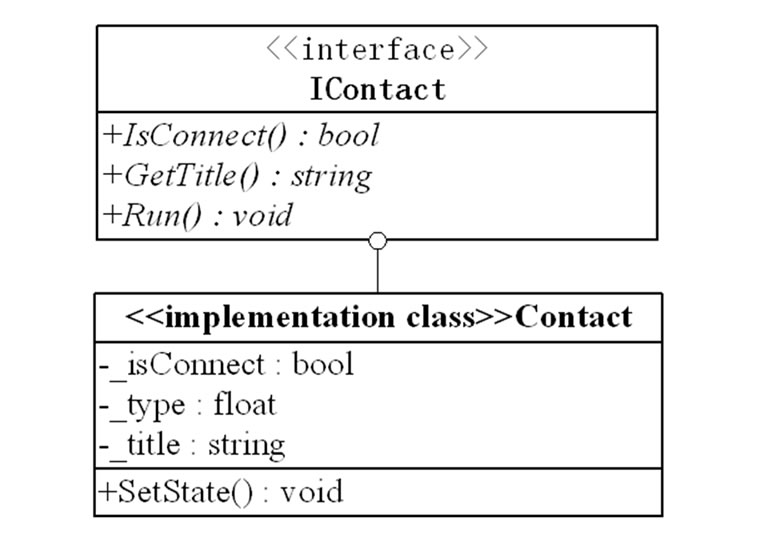
Figure 2. The class diagram of the relay coil.
SetStandardVlotage(); // set _standardVoltage of the coil IsExciting(); // return the excitation state of the coil GetTitle(); // return _title Run(); // to judge whether the coil should be excited The attributes and methods of CurrentRelay are similar to VoltageRelay. Figure 3 shows the class diagram of the contact. Its main attributes and methods are as follows:
_isConnect: // the state of the contact(open or closed)
_type: // the type of the contact(normally open or normally closed)
_title: // an attribute corresponding to the one in the relay coil, when they are equal,the contact is controlled by the coil SetState(): // set _isConnect of the coil

Figure 3. The class diagram of the contact.
The line is a special user control, connects two user controls, which are the member variables of the line: control1 and control2.These two member variables are also used in the all paths searching algorithm, as demonstrated in Section 4.
Besides the graphical interface of the circuit elements, the edit function for LD is also presented, of which the class diagram is shown in Figure 4. It is developed based on the command pattern, which encapsulates the detail of processing the messages. The functions of the controls such as adding, copying, cutting, moving and plastering can be performed through the menu or the shortcut keys. The function Add() of the menu is to add the user controls to the panel. Clicked() is to select an user control and generates the corresponding instance of the Command subclass, then call the function Execute() and sends the requirements to the control, which determines what to do. As mentioned above, based on the Command pattern, the details of the execution after sending a message is transparent for the menu.
Figure 5 shows the graphical interface corresponding to Figure 1, The right part of the interface is the library of circuit elements. After designing the interface, the control function of LD should be implemented, as presented in Section 4.
4. All Paths Searching Algorithm
As mentioned in Section 2.The main task to achieve the control function of LD is to search all the paths between and the live wire(LW) and the null line (NL), which can be implemented through conforming LD to an undigraph, as shown in Figure 6" target="_self"> Figure 6. ((R) represents the relay coil,(C) represents the contact). Each user control in the undigraph can be seemed as a vertex except the line, which is seemed as an edge. The line varible previousLine doesn’t
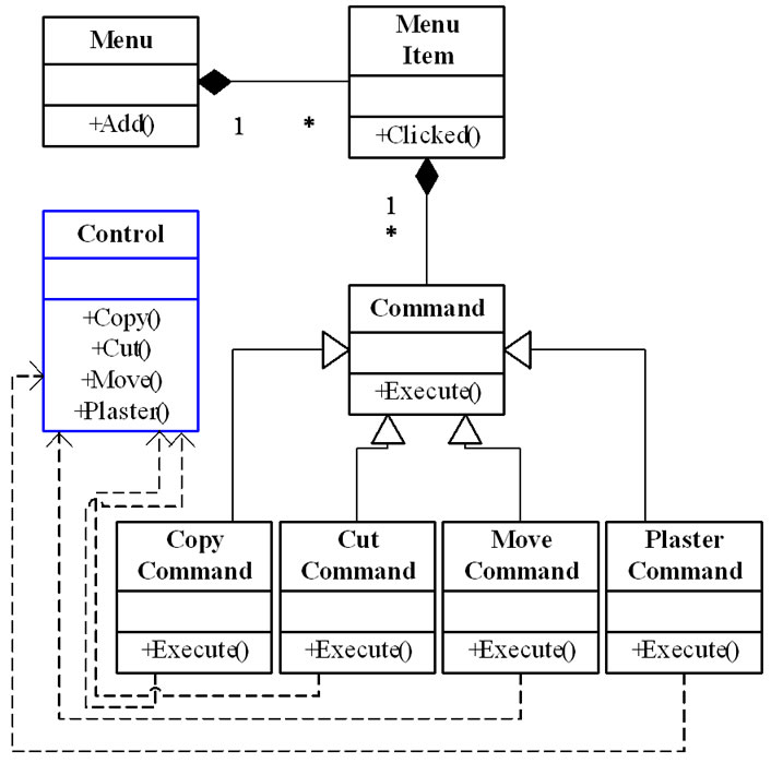
Figure 4. The class diagram of edit functions.
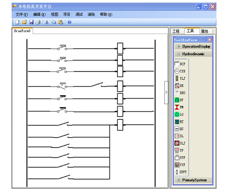
Figure 5. The graphical interface.
exist, but only for the algorithm.
Important variables and functions during the algorithm execution are as follows:
1) myStack: A stack variable, insert, remove and return the line varible at the top of itself (Its corresponding member functions are mystack. push(), mystack. pop() and mystack. peek()).
2) myHashtable: A hashtable variable, add or remove an element with the specified key and value (Its corresponding member functions are myHashtable.- add(), myHashtable.remove()), here the key and value are all line variables. The value is the immediate predecessor of the key which has been visited during the algorithm, each path can be extracted from myHashtable.
3) lineVisited: A table variable,includes two fields: the former is the line in the stack,the lattter is the immediate successor of the former and has been visited during the algorithm.The line variables can be inserted into or removed from lineVisited ((Its corresponding member functions are lineVisited.add(), lineVisited.remove()).
4) tempControl: An user control variable,represents the user control being visited during the algorithm execution.
5) previousLine: A line variable, it doesn’t exist in the LD but for the algorithm (previousLine. control1= null, previousLine.control2 = LW), as shown in Figure 6" target="_self"> Figure 6.
6) refresh (line, tempcontrol): Return an user control variable. The parameter line is a line varible, the parameter tempcontrol is an user control varible.If line.control1 = tempcontrol, return line.control2; else return line.control1.
The implementation of the algorithm is:
Step 1. Initialize the variables: myStack.push (previousLine), tempControl=LW. Goto Step2.
Step 2. If myStack is empty, then the algorithm ends, all paths are searched, else goto Step3.
Step 3.Search the immediate successor of myStack.- peek(), the successor must be not in myStack and not in lineVisited as the second field value with the first field value of myStack.peek(), if it exist (we suppose it named as templine), goto step4; else goto step7.
Step 4. lineVisited.Add (mystack.peek(), templine ), myHashtable.add(templine, mystack.peek()), myStack. push (tempLine), tempControl=refresh(templine, tempControl). Then if tempControl is LW,goto step5, else if tempControl is NL, goto step6, else goto step2.
Step 5. Remove the elements from lineVisited with the first field value of mystack.peek(),and if mystack. peek() isn’t previousLine, remove the elements from myHashtable with the key of myStack.peek().Refresh (myStack. peek(), tempControl), myStack.pop(), go to step2.
Step 6. A path is searched and can be extracted from myHashtable, if myStack.peek() isn’t previousLine, remove the elements from myHashtable with the key of myStack.peek(). tempControl = Refresh(mystack.peek(), tempControl), myStack.pop(), go to step2.
Step 7. Remove the elements from lineVisited with the first field value of mystack.peek(), and if mystack. peek() isn’t previousLine, remove the elements from myHashtable with key of myStack.peek(). tempControl =Refresh (mystack.peek(), tempControl), mystack.pop(), go to step2.
5. The Application Example and Analysis
As mentioned that the control function of LD should be implemented based on object-oriented thought. The running module which is irrelated to the edit environment, receiving the messages from the circuit elements, is to implement the control function.
The edit environment transfers all the paths searched with the algorithm to the running module, and when the state of the circuit element changes, it sends the corresponding message (including some attributes) to the module. After transformed to an undigraph in Figure 6, LD in Figure 1 is taken as an example to illustrate the whole process. Paths searched between live wire and null line with the algorithm are as follows:
Path1: LW-2YX1-2XJ1(R)-NL.
Path2: LW-3YX1-3XJ1(R)-NL.
Path3: LW-4YX1-4XJ1(R)-NL.
Path4: LW-5YX1-2SJ1-5XJ1(R)-NL.
Path5: LW-1WJ-6XJ1(R)-NL.
Path6: LW-3WJ-7XJ1(R)-NL.
Path7: LW-2XJ1(C)-BCJ1(R)-NL.
Path8: LW-3XJ1(C)-BCJ1(R)-NL.
Path9: LW-4XJ1(C)-BCJ1(R)-NL.
Path10: LW-5XJ1(C)-BCJ1(R)-NL.
Path11: LW-6XJ1(C)-BCJ1(R)-NL.
Path12: LW-7XJ1(C)-BCJ1(R)-NL.
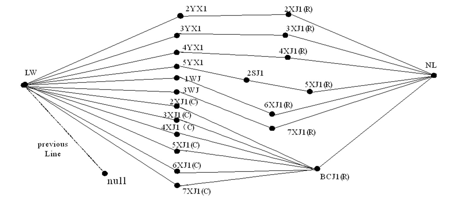
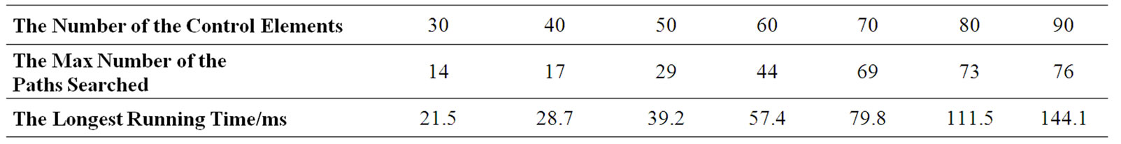
Table 2. The Longest Running Time According to the Number of the Control Elements.
When the pressures of the first stage is higher than the specified value, the pressure relay 2YX1 is open and sends a message including three attributes: its name (2YX1), control type(pressure relay) and state (open) to the running module. After receiving the message including some attributes, operations of the module are that: finds the path 2YX1 is in(path1), if there is an relay coil in path1(2XJ1(R)), it should be excited, and then, 2XJ1 (R) sends a message including its name, control type, state and _title, the module finds out the contact controlled by 2XJ1(R) from the user controls of all the paths: 2XJ1(C)(If there are many contacts controlled by 2XJ1(R), they all send messages to the running module), 2XJ1(C) sends a message, the module finds out 2XJ1(C) is in path7 and judges whether other contacts in path7 are all open, here there is only one and is open, the relay coil in path7(BCJ1) should be excited, send a message to the module, and lead to the accident shutdown. What should be noticed is that if there are many messages received, the module complies with FIFO rule.
From the process above, it proves the validity of the algorithm and its essence is to search all the paths between two vertices. The algorithm excludes the loops with the table varible: lineVisited, and store the paths with the hashtable varible: myHashtable. Generally, there are 30-90 control elements in the LD. Table 2 shows the longest running time with the proposed algorithm according to the maximum number of the paths searched with different number of control elements. (It runs on a platform of Core (TM)2 CPU with 512 Megabytes memory). When there are 90 control elements and 76 paths, the longest running time is no more than 150ms, so it can be concluded that the LD system can meet the real-time request in the hydropower simulation system.
6. Conclusions
In this paper, a method to design an interface for LD is presented with typical class diagrams and the graphical interface, then an algorithm is proposed to implement the control function of LD through transforming LD to an undigraph and search all the paths between LW and NL. The application example and the analysis verify the validity of the algorithm. The running time is shown at last, it proves that the LD system with the algorithm can meet the real-time request in the Hydropower simulation system.
7. Acknowledgements
The authors are grateful to the support of the Cultivation Fund of the Key Scientific and Technical Innovation Project, Ministry of Education of China (NO.708026) and would like to thank personnel of Embedded Key Lab at Northeastern University for their help.
8. References
[1] P. Sanderson, W. B. L. Wong, S. Choudhury, and R. Memisevic, “Hydro scheme control in a deregulated environment: Cognitive work models and design implications,” Annual Meeting of the Human Factors and Ergonomics Society, Santa Monica, CA, 2003.
[2] J. R. Hajdukiewicz and K. J. Vicente, “What does computermediated control of a thermal-hydraulic system have to do with moving your jaw to speak?” Ecological Psychology, Vol. 16, No. 4, pp. 255-285, 2004.
[3] R. Memisevic, P. Sanderson, S. Choudhury, and W. Wong, “A low-cost, easy-to-use, real-time power system simulator,” in Proceedings of International Conference on Power and Energy Systems, Clearwater Beach, FL, 2004.
[4] Y. Su, H. Zhao, W. J. Su, and Y. Xu, “GHS: Research and application of grid based hydroelectrical simulation system platform,” Journal of System Simulation, Vol. 17, No. 5, pp. 1230-1233, 2004.
[5] E, R. R. Kato, O. Morandin Jr., P. R. Politano, and H. A.
Camargo, “A modular modeling approach for CNC machines control using Petri nets,” in Proceedings of International Conference on Systems, Man and Cybernetics, Nashville, TN, Vol. 5, pp. 3417-3152, 2000.
[6] J.-L. Chirn and D. C. Mcfarlane, “Petri net based design of ladder logic diagram,” Working paper, Institute for manufacturing, University of Cambridge, UK, 2000.
[7] H. S. Kim, W. H. Kwon, and N. Chang, “A translation method for ladder diagram with application to a manufacturing process,” in Proceedings of International Conference on Robotics and Automation, Vol. 1, pp. 793-798, 1999.
[8] X. L. Cui and Z. C. Zhou, “The algorithm of transformation between the ladder language and the sentence table language of PLC,” Microelectronics and Computer, China, Vol. 1, No. 17, pp. 26-30, 2000.
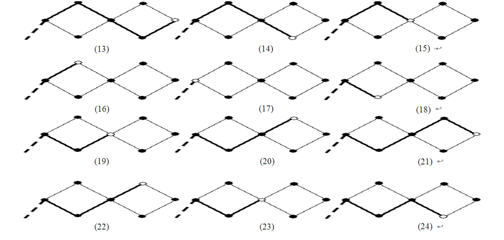
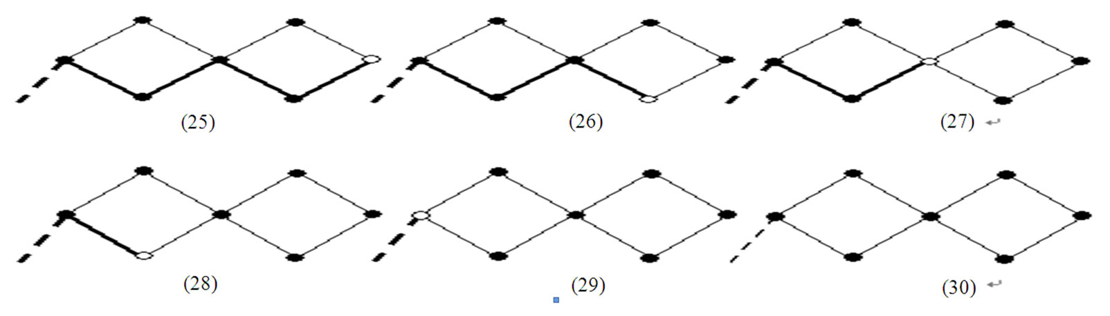
Appendix
The algorithm excution in another complex undigraph with two loops is demonstrated as follows: the thick edges represents the lines in myStack, the white vertex represents the variable tempControl.