Wireless Engineering and Technology
Vol.3 No.4(2012), Article ID:24197,4 pages DOI:10.4236/wet.2012.34034
Compact Wideband Rectangular Monopole Antenna for Wireless Applications
![]()
1Department of Applied Electronics, Gulbarga University, Gulbarga, India; 2University Science Instrumentation Centre, Gulbarga University, Gulbarga. India.
Email: sm_naveen_82@yahoo.com, vanirm12@rediffmail.com
Received October 26th, 2011; revised November 26th, 2011; accepted December 15th, 2011
Keywords: UWB; Monopole Antenna; Slots; Stubs
ABSTRACT
This article presents a compact wideband microstrip-fed planar monopole antenna composed of a rectangular patch and slotted ground structure. By placing pair of symmetrical square stubs, making slots in the stubs, putting stubs on the sides of the radiating patch, gives wide-band characteristics. The antenna only one of its kinds in structure, small in size and simple design due to less number of design parameters, compared with the existing UWB antennas in the literature. The bandwidth, radiation pattern and other antenna parameters are at acceptable level. IE3D method of moments based simulation software is used for design and analysis. The simulated results are confirmed by conducting experiments with the help of Rohde and Schwarz, German make ZVK model No. 8651 Vector Network Analyzer and discussed.
1. Introduction
There are rapid developments in wireless communication systems to meet the growing demands for various communication services. However, the technologies for wireless communication still need to be improved further to satisfy the higher resolution and higher data rate requirements. Recently, UWB communication system covering from 3.1 to 10.6 GHz has been released by the FCC in 2002. UWB system requires a compact antenna providing wideband characteristic over the whole operating band. Due to their appealing features of wide bandwidth, simple structures, omnidirectional patterns and ease of construction, planar metal-plate monopole antennas have been proposed for such applications [1]. A microstrip-fed planar monopole antenna is thus suitable for integration with handheld terminal owing to its attractive features such as low profile, low cost and light weight [2].
Recently various wideband monopole configurations such as circular disc, rectangular patch and ring have been reported. In particular circular disc and rectangular monopole antennas have been widely studied due to the feature of simple structure [3]. Also several planar monopole antennas with various shapes have been investigated. For ex., some of these antennas include E-shaped slot, S-shaped-slot, use defected ground structure and slot in the tapered radiating etc. These antennas are either relatively large, have limited impedance bandwidth or exhibit non–omnidirectional radiation patterns [4-6].
So, in this paper an attempt is made to use stubs to obtain the wide bandwidth with reduced size. The technique used in this article presents the inherent advantages of planar antennas for operation behind the UWB spectrum as defined by FCC. This is achieved by putting stubs in ground plane and in the sides of the radiating patch of a microstrip fed monopole antenna which acts like a resonant structure. Further the slots have been introduced in the stubs of ground plane and the study was made. Radiation patterns in E-plane and H-plane have been presented.
2. Antenna Design
The geometrical configuration of the proposed wideband printed monopole antenna is shown in Figure 1. The antenna with substrate width 16 mm and height 18mm is constructed on Glass Epoxy material with thickness of 1.6 mm and dielectric constant εr = 4.4. The microstrip feedline having 2 mm width is used to excite the proposed antenna. The basic antenna structure is a rectangular patch of 11 mm × 7 mm with two notches of dimensions 1 mm × 2 mm at the two lower corners of the patch and 1 mm × 1 mm at the upper corners of the patch. The gap between the patch and ground plane is 2 mm. The dimensions of the ground plane is 16 mm × 4 mm. This is basic antenna i.e., Printed Rectangular Monopole Antenna (PRMA) named as Antenna 1.
In the next step the pairs of square stubs with size
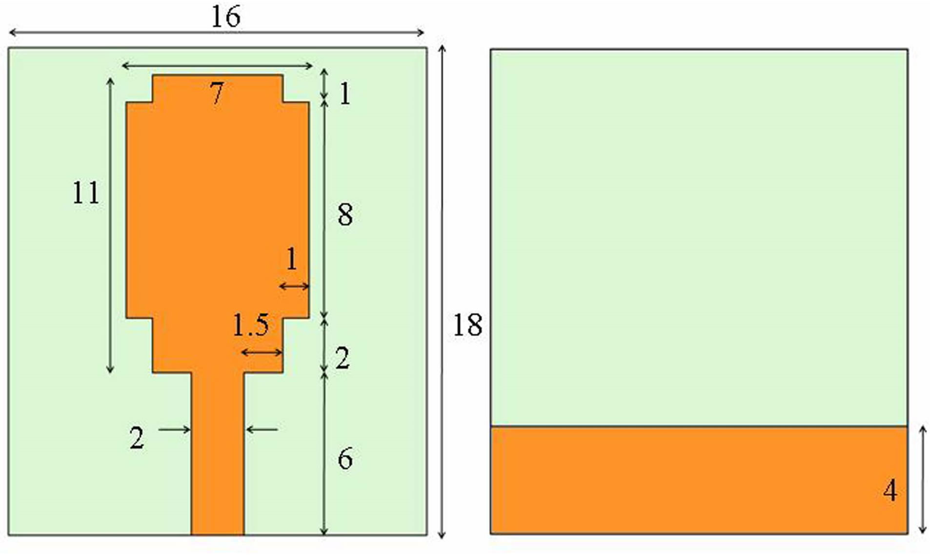
Figure 1. Antenna 1 (the dimensions are in mm).
(2 × 2) mm have been placed at a distance of 5 mm in the planar ground plane, it is Antenna 2 and it is shown in Figure 2. In Antenna 3, the slots have been placed in the stubs of the ground plane. The sizes of those slots are 1 × 3 mm is shown in Figure 3. Further another prototype antenna (Antenna 4) is designed by putting stubs of dimensions (1 × 1) mm on the sides of the radiating patch to get wide bandwidth (Figure 4). All the parameters of the antennas are optimized by using IE3D simulation software.
3. Simulation and Measurement Results
The proposed antennas were analyzed by using Mentor Graphics IE3D simulator and the fabricated antenna’s performance was measured using a Rohde and Schwarz, German make ZVK model No. 8651 Vector Network Analyzer. The simulated reflection coefficient or return loss of the proposed antennas are shown in Figure 5 The simulation results show impedance bandwidth between 4.9 & 12.5 GHz with respect to S11 < –10 dB reference level. The measured results of the antennas are shown in Figure 6 and these results exhibit impedance bandwidth between 4.3 to 13.35 GHz. However, the overall impedance bandwidth between 4.3 & 13.35 GHz is consistent and more than FCC range with respect to higher frequency. When the stubs have been placed in the radiating patch (Antenna 4), it is observed that there is little increase in the bandwidth around 550 MHz compared to Antenna 1.
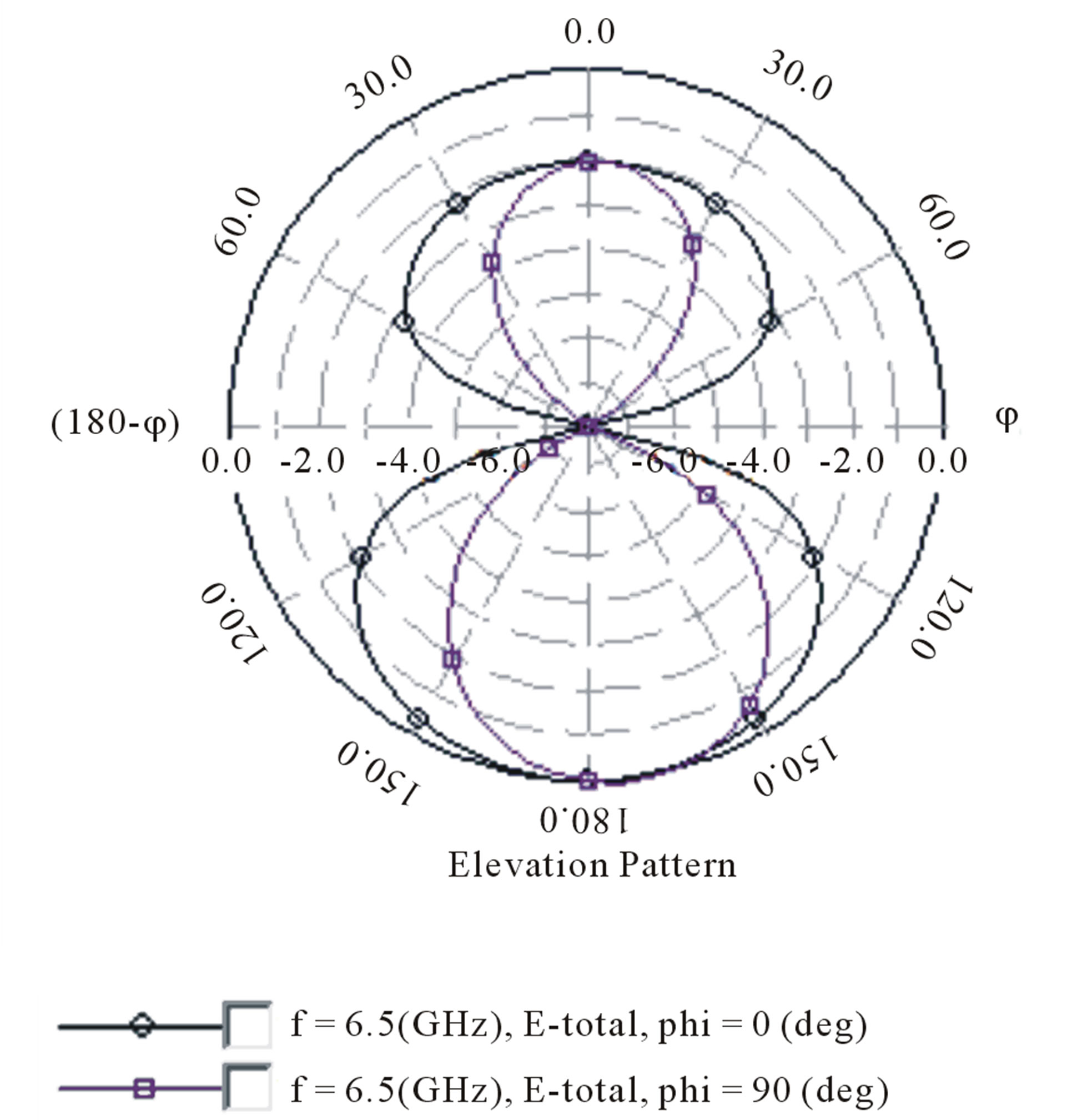
The simulated and measured results are shown in Table 1. From the results it is clear that bandwidth of Antenna 2 is more than Antenna 1 and it is due to the stubs on the ground plane. By putting slots in the stubs of ground plane (Antenna 3) the band width has increased to 260 MHz. Similarly by placing the stubs in the radiating patch (Antenna 4) gives little more increase in the bandwidth around 550 MHz. Further the antenna radiation patterns in E-plane and H-plane were studied and the radiation patterns for Antenna 4 are shown in Figures 7 (a) and (b). It is observed that E-plane pattern is bidirectional and H-plane pattern is omnidirectional.
The Figure 8 shows the three dimensional view of radiation pattern. Figure 9 simulated real part of the input
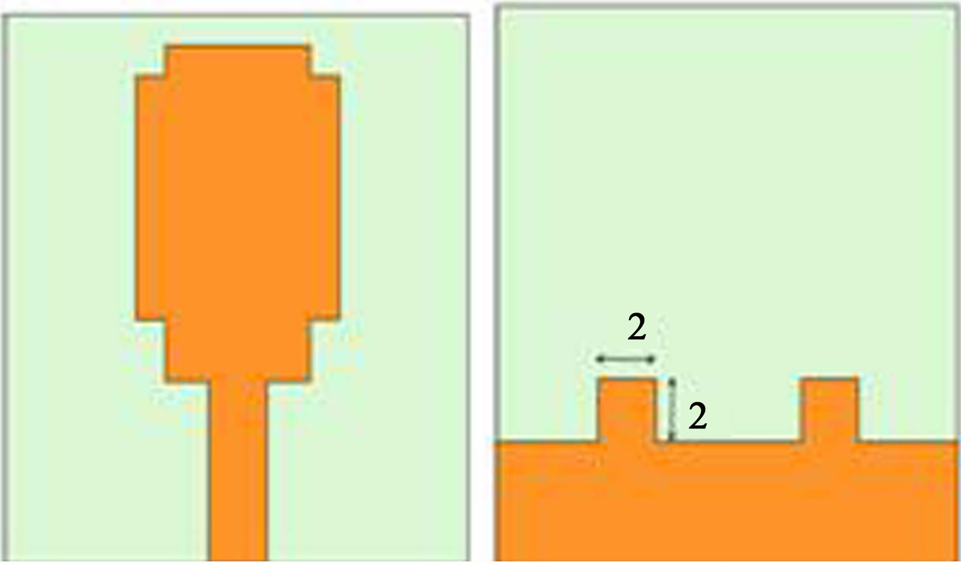
Figure 2. Antenna 2 (the dimensions are in mm).
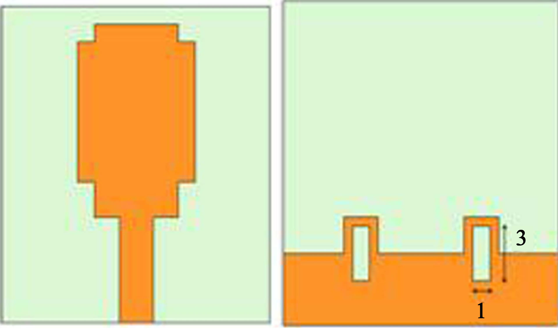
Figure 3. Antenna 3 (the dimensions are in mm).
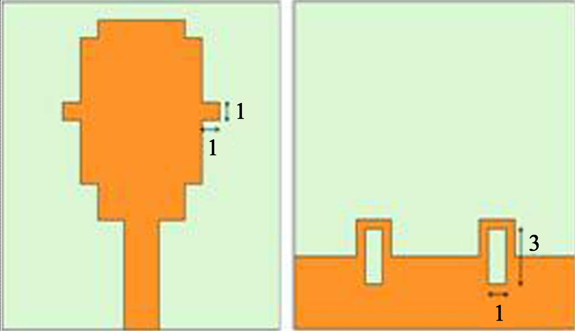
Figure 4. Antenna 4 (the dimensions are in mm).
impedance over the bandwidth of interest. The variation of real part of impedance is between 27.96 Ω to 93 Ω. This shows that the input impedance remains almost constant over the entire bandwidth [4]. It can be observed that from the Figure 10, the current is concentrated on the edges of the radiating patch and corners of the stubs. Therefore the antenna impedance changes due to the resonant properties of the L-shaped notches and stubs.
4. Conclusion
A compact wideband rectangular monopole antenna with pair of symmetrical square stubs, slots in the stubs on the ground plane and stubs on the radiating patch has been

Figure 5. Simulated reflection coefficient of proposed antennas.
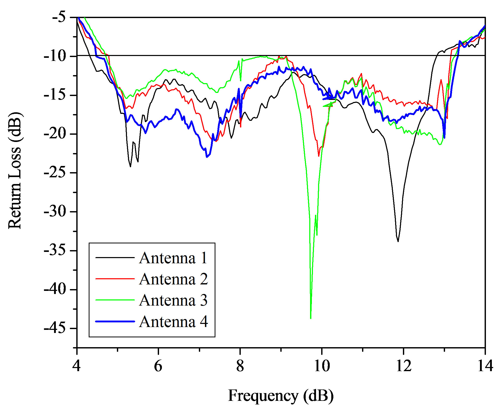
Figure 6. Measured reflection coefficient of proposed antennas.
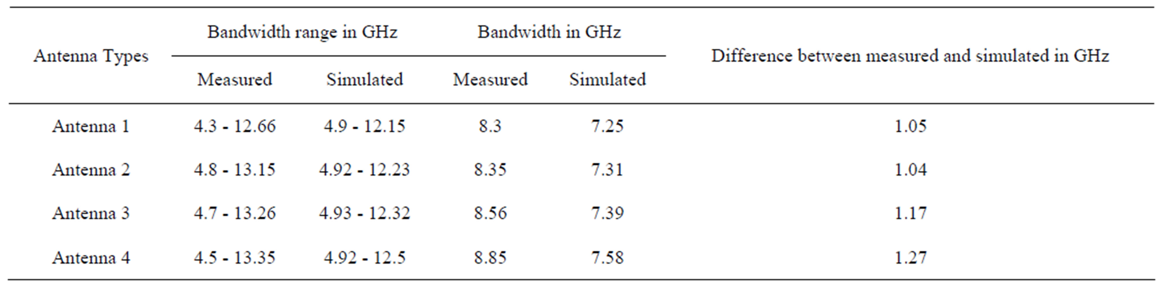
Table 1. Simulated and measured results of proposed antennas.
 (a)
(a) (b)
(b)
Figure 7. Simulated; (a) E-plane radiation pattern; (b) H-plane radiation pattern of proposed antennas.
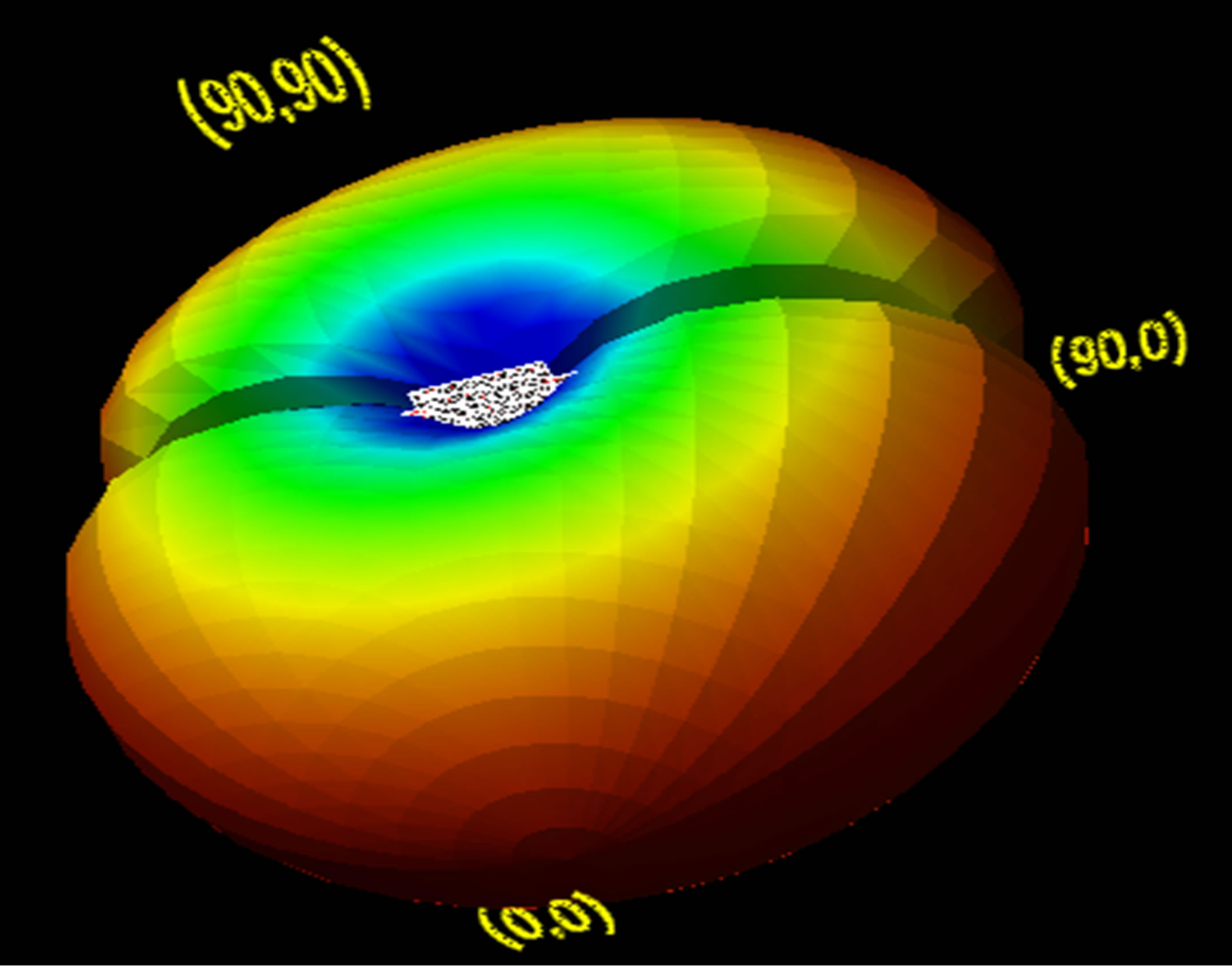
Figure 8. Three dimensional view of radiation pattern.
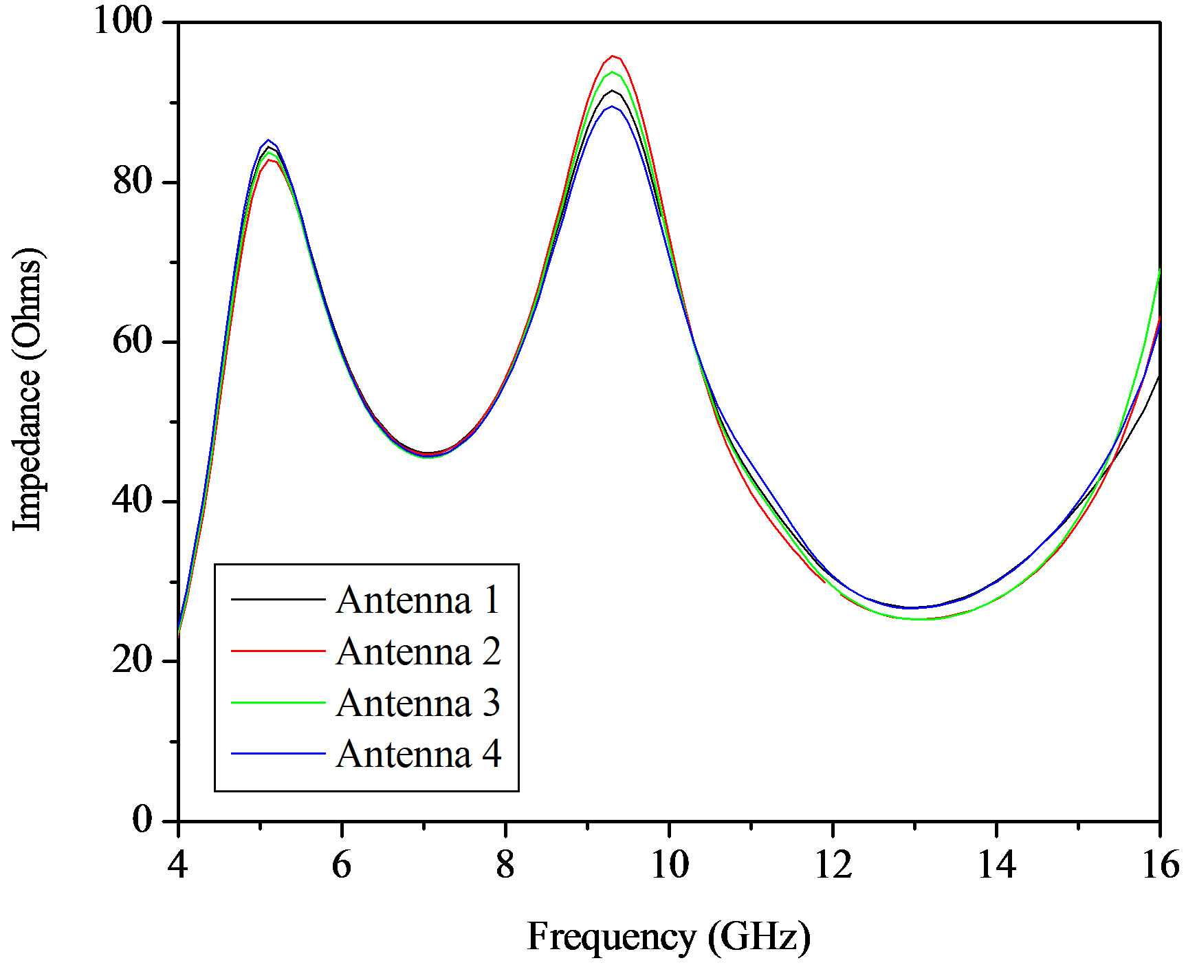
Figure 9. Simulated real part of the input impedance.
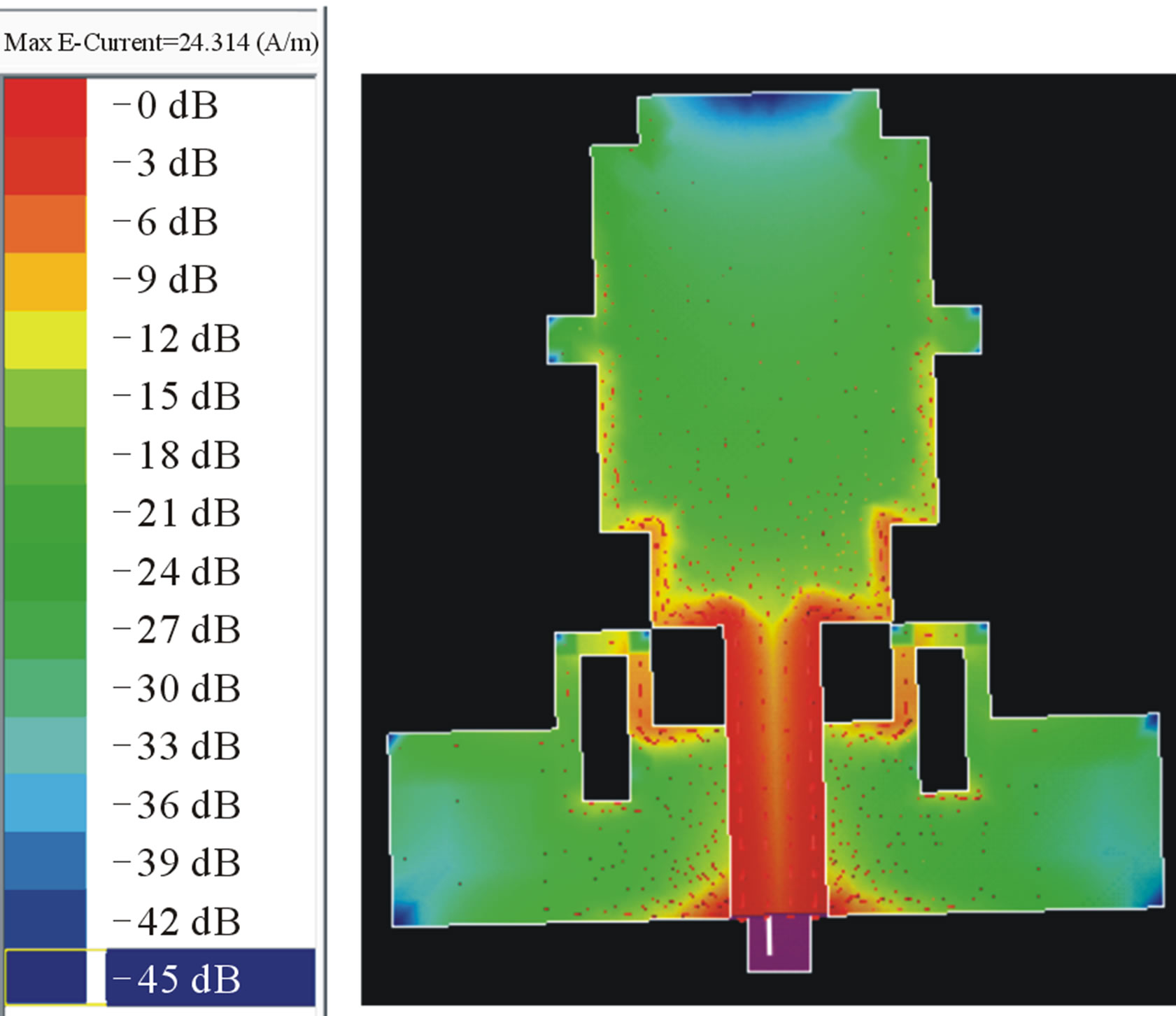
Figure 10. Current distribution of Antenna 4 by using IE3D simulator.
studied. All prototype antennas operate over UWB frequency range of 4.3 to 13.35 GHz. They provide bidirectional radiation pattern in E-plane and omnidirectional radiation pattern in H-plane. In addition the antennas geometry is of a relatively simple configuration enabling easy fabrication at low cost.
REFERENCES
- W. Choi, J. Jung, K. Chung and J. Choi, “Compact Wideband Printed Monopole Antenna with Frequency BandStop Characteristic,” IEEE Antennas and Propagation Society International Symposium, Vol. 3A, 2005, pp. 606- 609.
- M. Akbari, M. Koohestani, Ch. Ghobadi and J. Nournia, “A New Compact Planar UWB Monopole Antenna,” International Journal of RF and Microwave ComputerAided Engineering, Vol. 21, No. 2, 2011, pp. 2794-2796.
- S. T. Choi, K. Hamaguchi and R. Kohno, “A Novel Microstrip-Fed Ultrawideband Triangular Monopole Antenna with Wide Stubs,” Microwave and Optical Technology Letters, Vol. 51, No. 1, 2009, pp. 239-242. doi:10.1002/mop.23989
- M. Naser-Moghadasi, R. A. Sadeghzadeh, M. Katouli and B. S. Virdee, “Ultra-Wideband Microstrip Antenna with Enhanced Impedance Bandiwdth,” Microwave and Optical Technology Letters, Vol. 52, No. 4, 2010, pp. 95-97. doi:10.1002/mop.25072
- A. A. Jamali, A. E. Gaafar, A. Elaziz, A. Elmonem and A. Elaziz, “Spiral Tuning Stub CPW-Fed UWB Slot Offset, Edge Cleft and Edge Slotted Antennas,” Wireless Engineering and Technology, Vol. 2, No. 3, 2011, pp. 146- 152. doi:10.4236/wet.2011.23021
- M. Hayouni, F. Choubani, M. Densden, T. H. Vuong and J. David, “A Novel Compact Ultra-Wideband Rectangular Shaped Antenna,” Progress in Electromagnetics Research Symposium Proceedings, Marrakesh, 20-23 March 2011.