Wireless Engineering and Technology
Vol.2 No.2(2011), Article ID:4547,9 pages DOI:10.4236/wet.2011.22013
Aperture Coupled Microstrip Antenna for Dual-Band
![]()
School of Studies in Electronics, Pt. Ravishankar Shukla University, Raipur, India.
Email: rkv_786@yahoo.com, drsanjaytiwari@gmail.com
Received October 20th, 2010; revised February 25th, 2011; accepted February 28th, 2011.
Keywords: Aperture coupled Microstrip antenna, Dual-band antenna, Network analyzer, Microstrip line feed
ABSTRACT
This paper presents air gap aperture coupled microstrip antenna for dual-band operation over the frequency range of (2.9 to 6.0 GHz). This antenna differs from any other microstrip antenna with their feeding structure of the radiating patch element. Input signal couples to the radiating patch trough the aperture that exists on the ground plane of microstrip feed line. The dual-band achieved by variation of air gap [2 mm to 6 mm] between single patch antenna and aperture coupled microstrip antenna. The main advantage of this type antenna is increased the bandwidth of the antenna as compared to a single layered patch antenna. The two resonant frequencies can vary over a wide frequency range and the input impedance is easily matched for both frequencies. The obtain ratios of resonance frequencies are variable from 2.1 GHz to 1.1 GHz with increasing the air gap between single patch and aperture coupled microstrip antenna. The measured return loss [–14 dB] exhibits an impedance bandwidth of 35%. The input impedance and VSWR return loss have been measured with the help of Network analyzer.
1. Introduction
The use of microstrip antenna has become quit popular because of their properties such as low profile, light weight, compact [1]. The aperture coupled microstrip antenna first proposed by Pozar [2] in 1985 has a number of advantages over other feeding method involving galvanic contact between the antenna and feed line. The aperture is usually centered with respect to the patch where the patch has its maximum magnetic field. A simple technique for changing the resonant frequencies with out resulting to a new antenna [3,4]. The idea is introduce an air gap variation between the single patch and aperture coupled microstrip antenna. The air gap variations affect the resonant frequencies. The resonant frequencies can therefore be tuned by the variation of air gap. The band width will also increases particularly due to the increases in the height of the dielectric medium. A number of experiment and theoretical structure have been carried out to analyze and design aperture coupled microstrip antenna. Full wave analysis using the method of moments has been used to determine the various antenna parameters [5-8]. A transmission line [9] and cavity model [10] have been proposed as efficiently analysis and design method. Recently an effect of the different shapes aperture coupled microstrip slot antenna [11] and circularly polarized aperture coupled microstrip antenna with resonant slot and a screen was proposed [12]. Optimum design of an aperture coupled microstrip patch antenna describe in details [13]. An Introduction of aperture coupled microstrip slot antenna with microstrip line feed has been discussed [14]. In this paper a simple but accurate design method from air gap aperture microstrip antenna is presented. The dual-band operation of air gap aperture coupled microstrip antenna are useful in many application such as dual-band transmit receive models for space vehicles.
2. Antenna Design
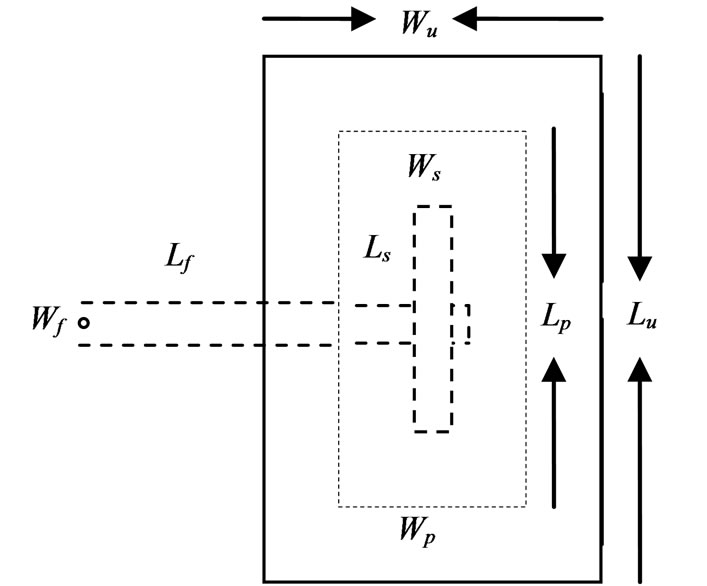
The proposed air gap aperture coupled microstrip antenna is shown in Figure 1(a). In this figure there are two antennas.
1) Upper patch (single patch)
2) Aperture coupled patch with microstrip line
The single patch is design by using 3.0 GHz and the aperture coupled patch is design at 2.5 GHz. The side view of the air gap aperture coupled microstrip antenna is shown in Figure 1(b). The radiating microstrip patch element is printed on the top of the substrate and the
 (a)
(a)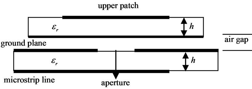 (b)
(b)
Figure 1. (a) Top view of Aperture couple microstrip antenna; (b) Side view of Aperture couple microstrip antenna.
microstrip feed line is printed on the bottom of the feed substrate. The first thing to design of the patch is choosing a suitable substrate of suitable thickness. Taking low dielectric substrate to increases the band width and radiation efficiency of the antenna. A microstrip antenna in its simplest form consists of a radiating patch on one side of dielectric substrate and a ground plane on the other side. Transmission line model is used for analyzing the patch antenna for rectangular shapes. A simple patch antenna can be designed for the given dielectric constant.
2.1. Length and Width of Single Patch
To design the rectangular patch width of the antenna is given by
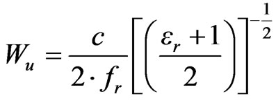 (1)
(1)
where c = velocity of light W = width of the microstrip patch
 = Dielectric constant of the substrate Length of the resonant element is given by
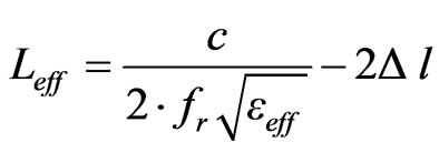 (2)
(2)
where
 = Effective dielectric constant of the substrate
 = Line extension
 and
and  can be expressed as
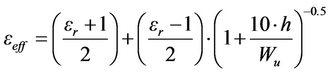 (3)
(3)
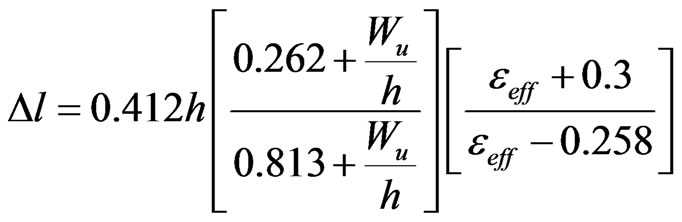 (4)
(4)
where h is the thickness of the substrate.
Finally the actual length of the single patch antenna is obtained as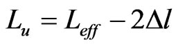 . The single patches were designed to operate at a resonant frequency of 3.0 GHz, their length and width were calculated to be Lu = 23.01 mm and width Wu = 30.01 mm respectively.
2.2. Length and Width of Aperture Coupled Patch
The dimension of aperture coupled microstrip antenna can also calculated by using above transmission equations. The dimension of aperture coupled microstrip antenna remaining was deigned at a resonant frequency of 2.5 GHz, their length and width were calculated to be Lp = 27.78 mm and width Wp = 36.18 mm respectively.
2.3. Slot Width
The width of slot affect coupling level from the feed lines to the patch. Generally the ration of the slot length to the slot width is kept typically as 10:1. In this paper the width of the slot is taken Ws = 1.0 mm.
2.4. Slot Length
The coupling level is primarily decided by the slot length. There are two types of the slot are used in aperture coupled microstrip antenna design they are resonate and non resonate type based on the length of length slot. If the slot length is comparable to the half of the wave length of the antenna it is called as the resonant slot. If small length slot are used it is non resonant.
2.5. Feed Line Width
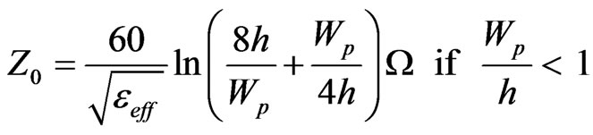
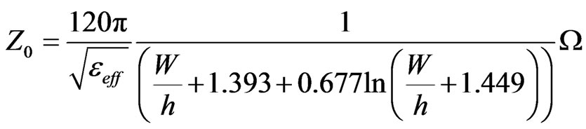
The physical size of the antenna derived from microstrip transmission line, the microstrip antenna is modeled as a length of transmission line of characteristics [15,16] impedance given by (5) and (6)
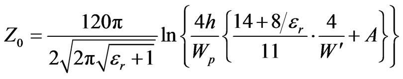 (5)
(5)
 (6)
(6)
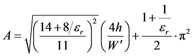
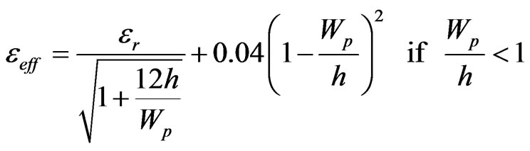
where 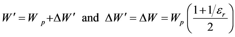 (7)
(7)
 (8)
(8)
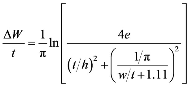
If we replace  with
with 
 (9)
(9)
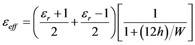
Otherwise
 (10)
(10)
 is expressed as follow
 (11)
(11)
Otherwise
Characteristics impedance evaluation of microstrip is important to determine the width of the feeding line calculated using equation (6). The width of a Z0 = 50 Ω
lime w = 3.0 mm.
2.6. Feed Line Position with Respect to Slot
For maximum coupling the feed line must be placed positioning to the centre of slot. Skewing the feed line from the slot will reduce the coupling as it will position the feed line toward the edge of slot.
2.7. Position of the Patch with Respect to Slot
For the maximum coupling the patch should be centered over the slot. Moving the slot in H-field direction little effects on the antenna performance. But if it is moved in E-field, it leads to reduction in coupling.
2.8. Length of Tuning Stub
The length stub is used to turn the excess reactance of the slot could antenna. He stub is typically slightly less than  in length.
3. Experimental Measurements
The air gap aperture coupled microstrip antenna was measured using network analyzer [Agilent E8363B A.04.06] for obtaining the desired dual-frequency behavior. The aim of air gap variation to see the how the resonant frequencies are shifting. The input impedance is easily matched by the variation of air gap. The variation of upper and lower resonant frequencies and their ration with air gap variation is shown in Table 1. In order to study the performance of designed air gap aperture coupled microstrip antenna return loss and band width were measured experimentally with air gap variation are shown in Table 2. The band width is achieved about 35% with air gap variations.
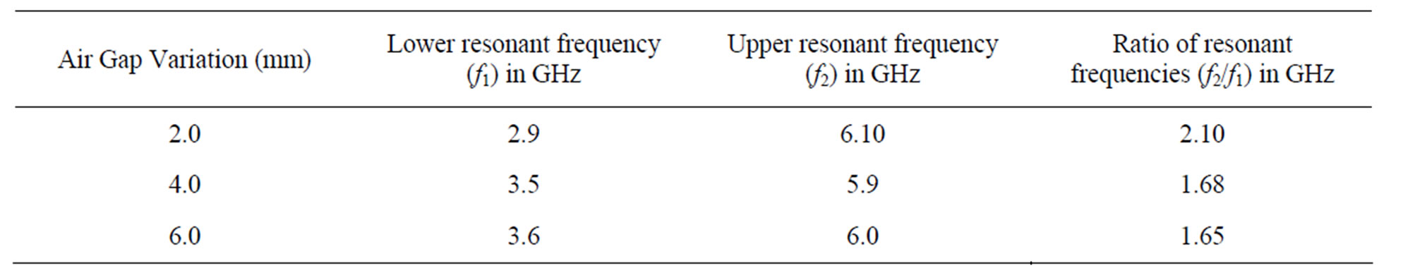
Table 1. Variation of upper and lower resonant frequencies and their ration with air gap variations.
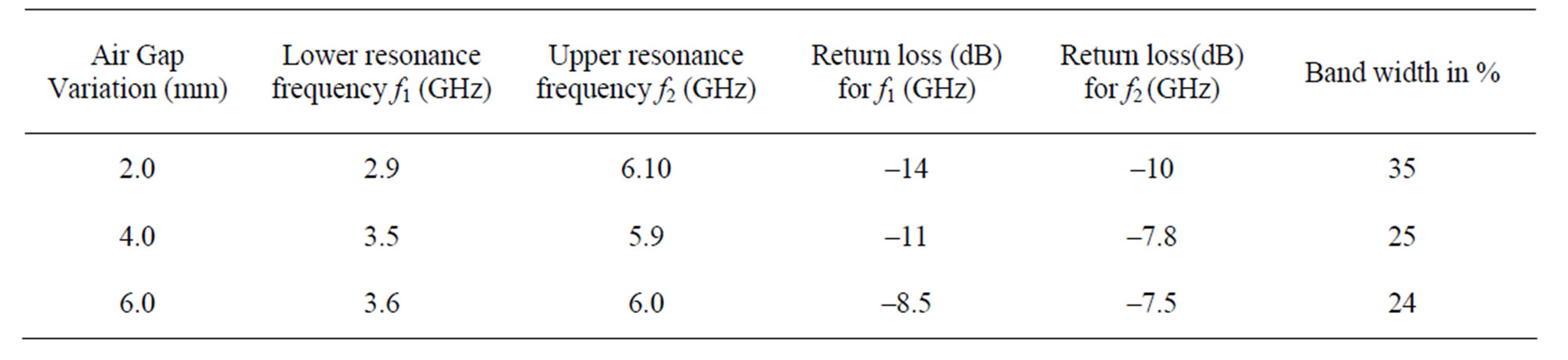
Table 2. Variation resonant frequencies, return loss and band width with the variations of air gap.
4. Design Parameters
For designing the air gap aperture coupled microstrip antenna following parameter were used.
Substrate material used Glass Epoxy
Thickness of the dielectric substrate h = 1.6 mm
Relative permittivity of the substrate er = 4.5
Design frequency for single patch antenna f1 = 3.0 GHz
Design frequency for aperture couples patch antenna f2 = 2.5 GHz
Thickness of the patch t = 0.0018 cm
Permittivity constant e0 = 8.85 × 10⁻¹² F/m
And designed values were calculated using the standard equations, which are given below.
The dimensions of single patch (Lu × Wu) = 23.01 × 30.15 mm
The dimension of aperture coupled patch antenna (Lp × Wp) = 27.78 × 36.18 mm
The dimensions of the slot (Ls × Ws) = 1.0 × 20.0 mm
The length of the microstrip line Lf = 14.70 mm
The width of the microstrip line Wf = 3.0 mm
5. Discussion of Result
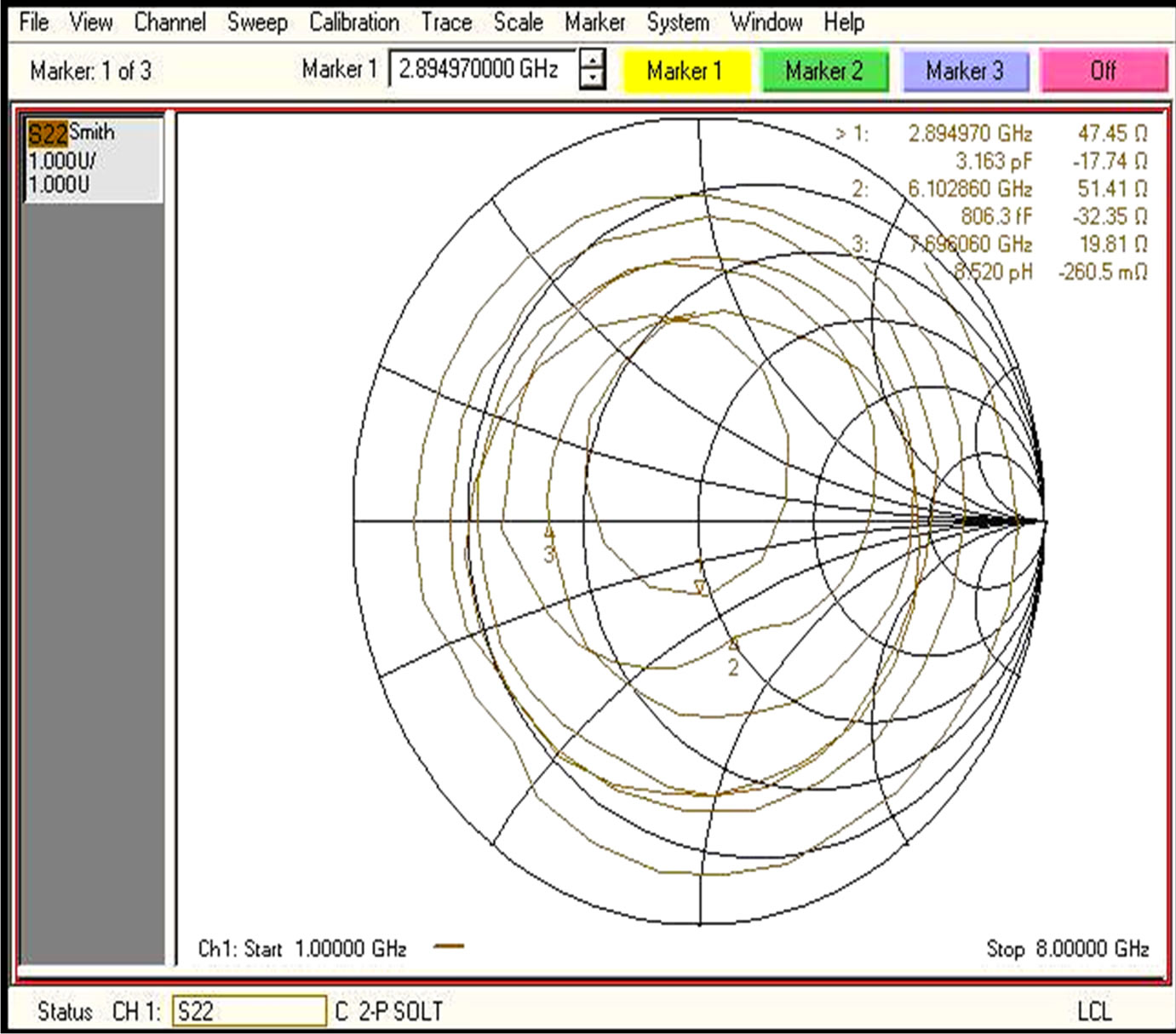
1) The variation of input impedance with frequency for aperture coupled microstrip antenna with air gap variation as shown in Figures 2(a)-(c). It is observed that when we are increasing the air gap [2 to 6 mm]variation between the single patch and aperture coupled microstrip antenna shows dual resonance in which lower resonance frequency increases where as upper resonance frequency is almost constant with increasing air gap.
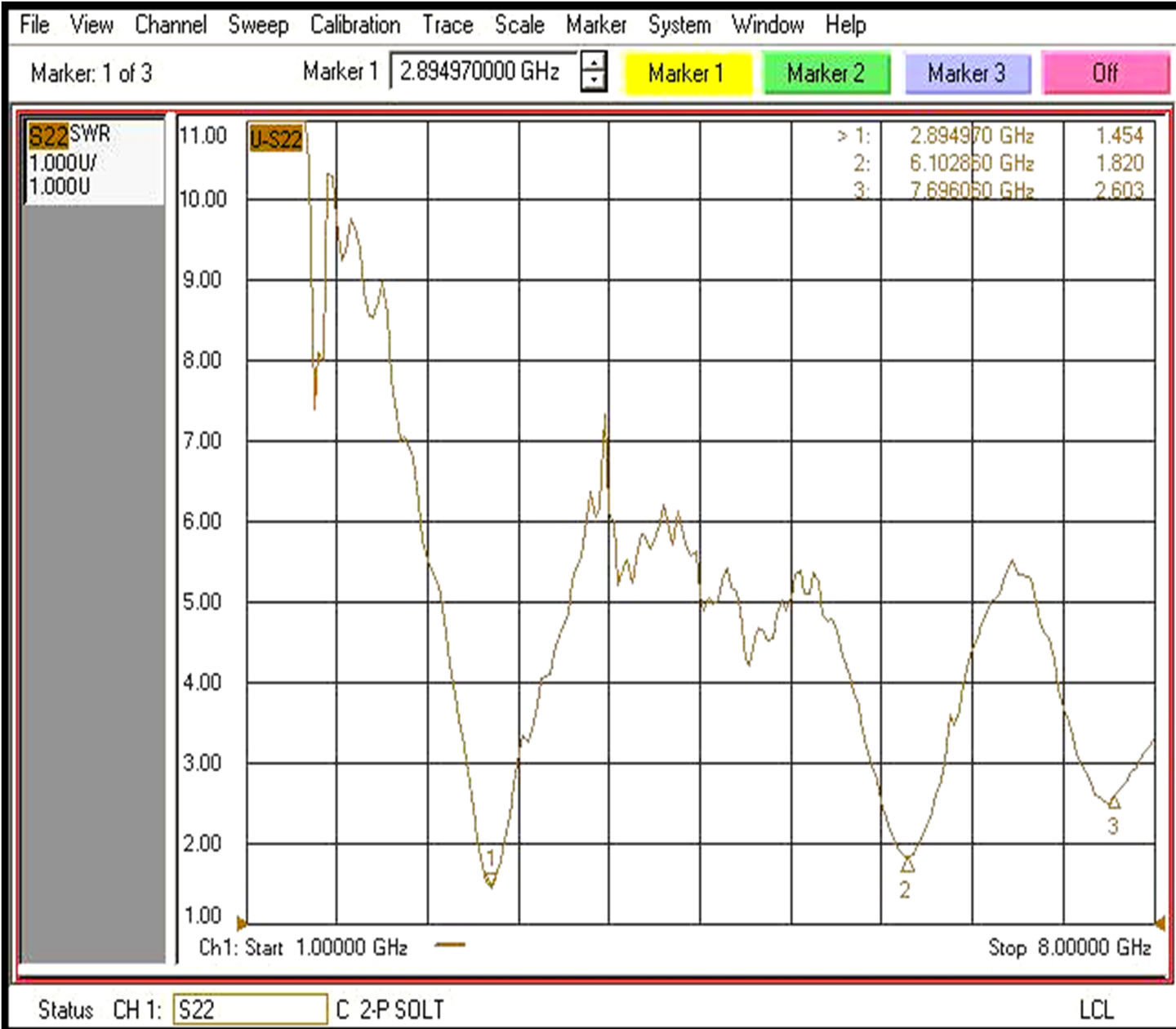
2) The variation of VSWR with frequency for aperture coupled microstrip antenna with air gap variation as shown in Figures 3(a)-(c). It is observed that the value of VSWR corresponding to lower resonance frequency is increases from 1.4 to 2.2 with increasing the air gap [20 to 6 mm] variation between the single patch and aperture coupled microstrip. Whereas at the upper resonance frequency, the value of VSWR is also increased from 1.8 to 2.3.
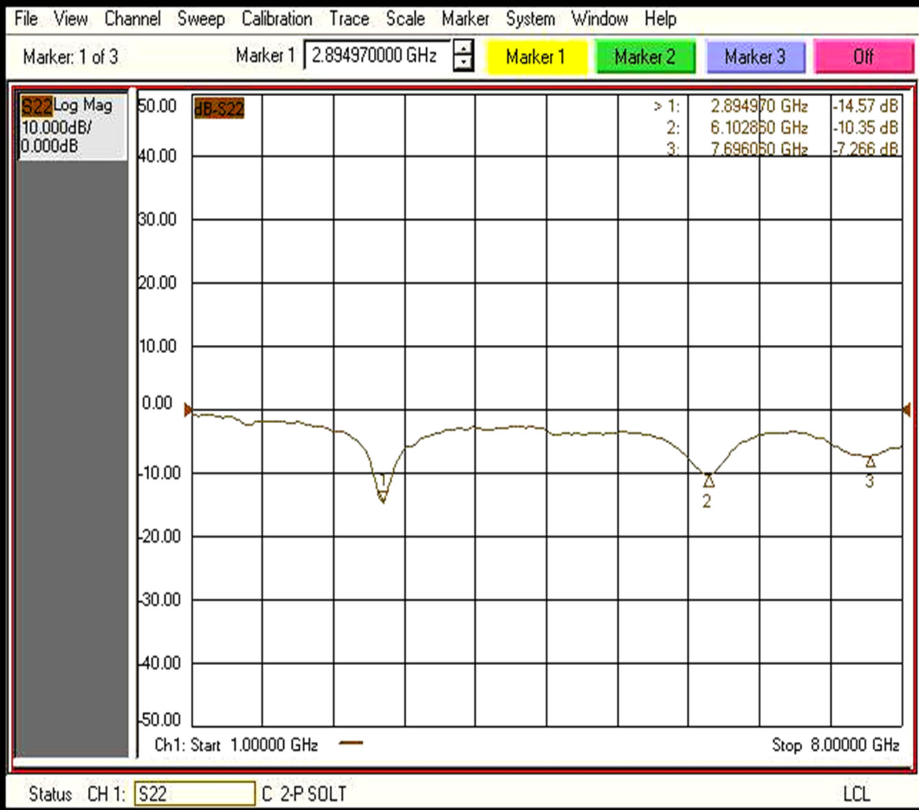
3) The variation of resonance frequencies with return loss is shown in Figures 4(a)-(c). It is observed that the value of return loss corresponding lower resonance frequency decreases from –14 dB to –8.5 dB with increases the air gap. Where as at upper resonance frequency is also decreases from –10 dB to –7.5 dB with increases the air gap.
 (a)
(a)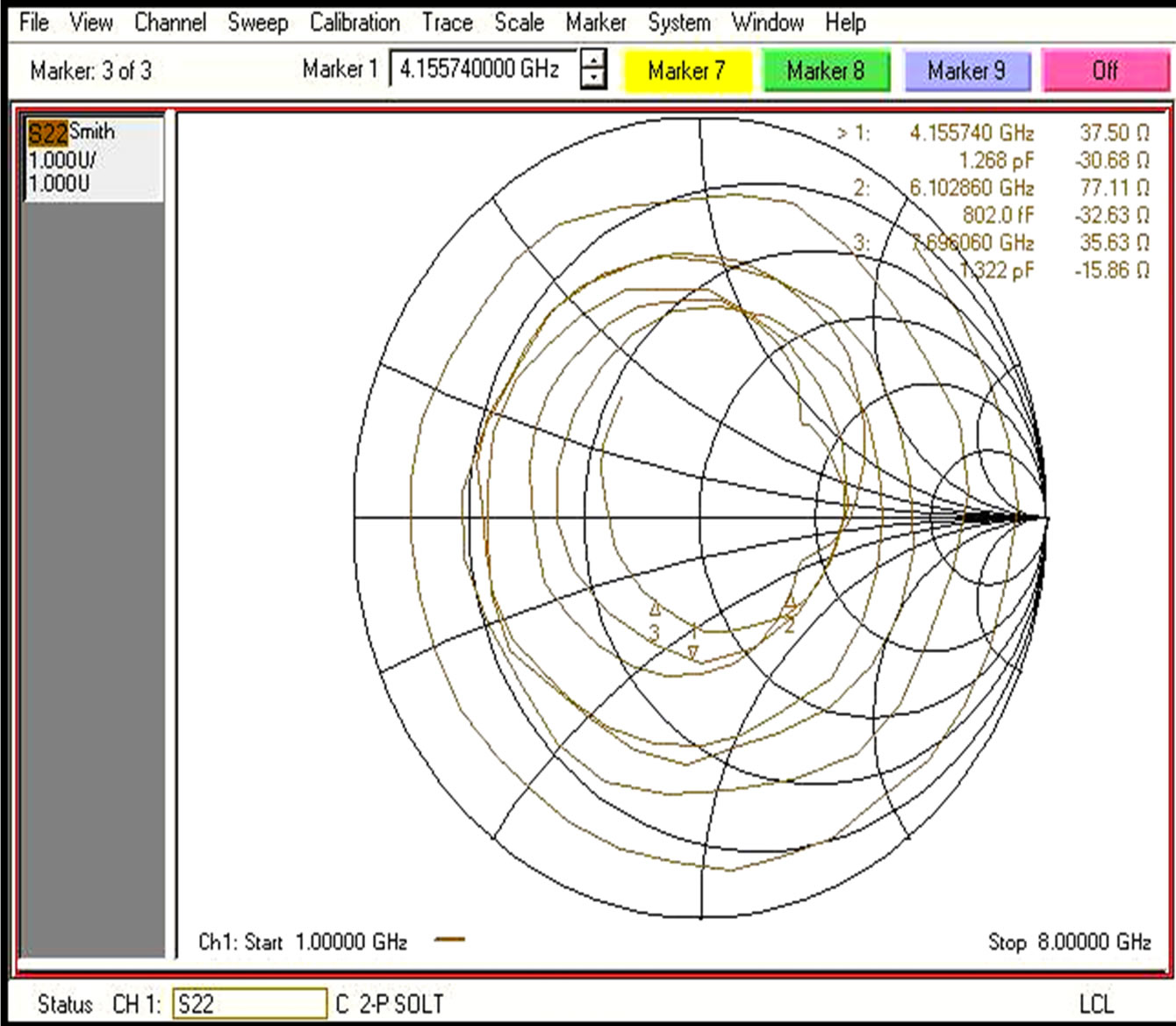 (b)
(b)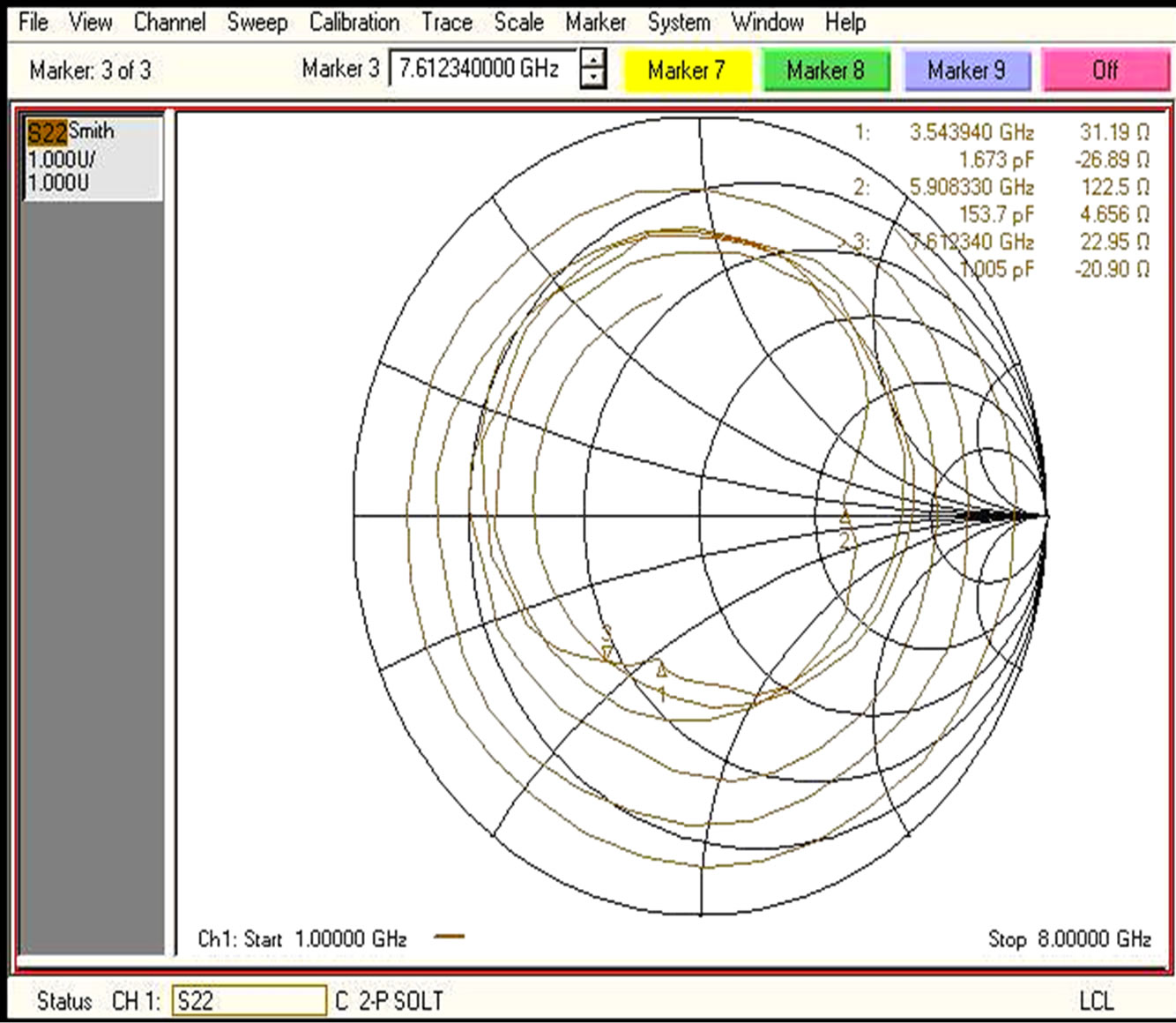 (c)
(c)
Figure 2. (a) The variation of input impedance with frequency for aperture coupled microstrip antenna with air gap variation = 2.0 mm; (b) The variation of input impedance with frequency for aperture coupled microstrip antenna with air gap variation = 4.0 mm; (c) The variation of input impedance with frequency for aperture coupled microstrip antenna with air gap variation = 6.0 mm.
 (a)
(a)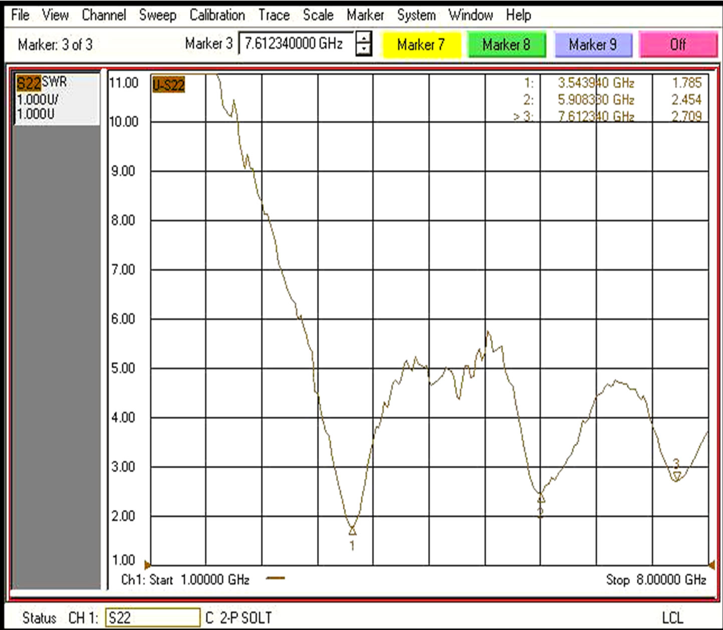 (b)
(b)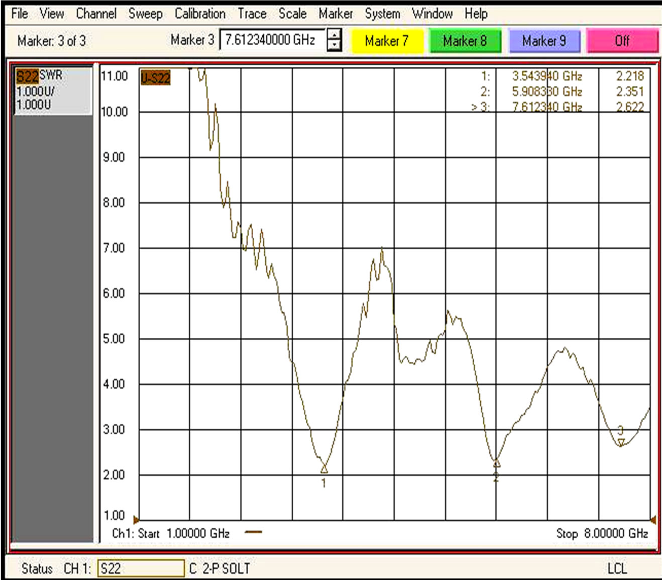 (c)
(c)
Figure 3. (a) The variation of VSWR with frequency for aperture coupled microstrip antenna with air gap variation = 2.0 mm; (b) The variation of VSWR with frequency for aperture coupled microstrip antenna with air gap variation = 4.0 mm; (c) The variation of VSWR with frequency for aperture coupled microstrip antenna with air gap variation = 6.0 mm.
 (a)
(a)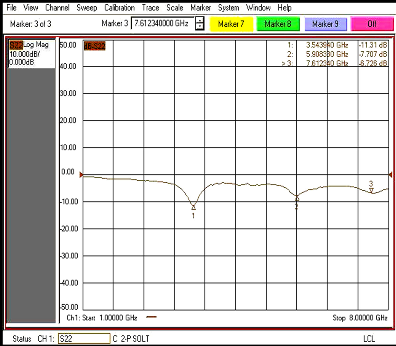 (b)
(b)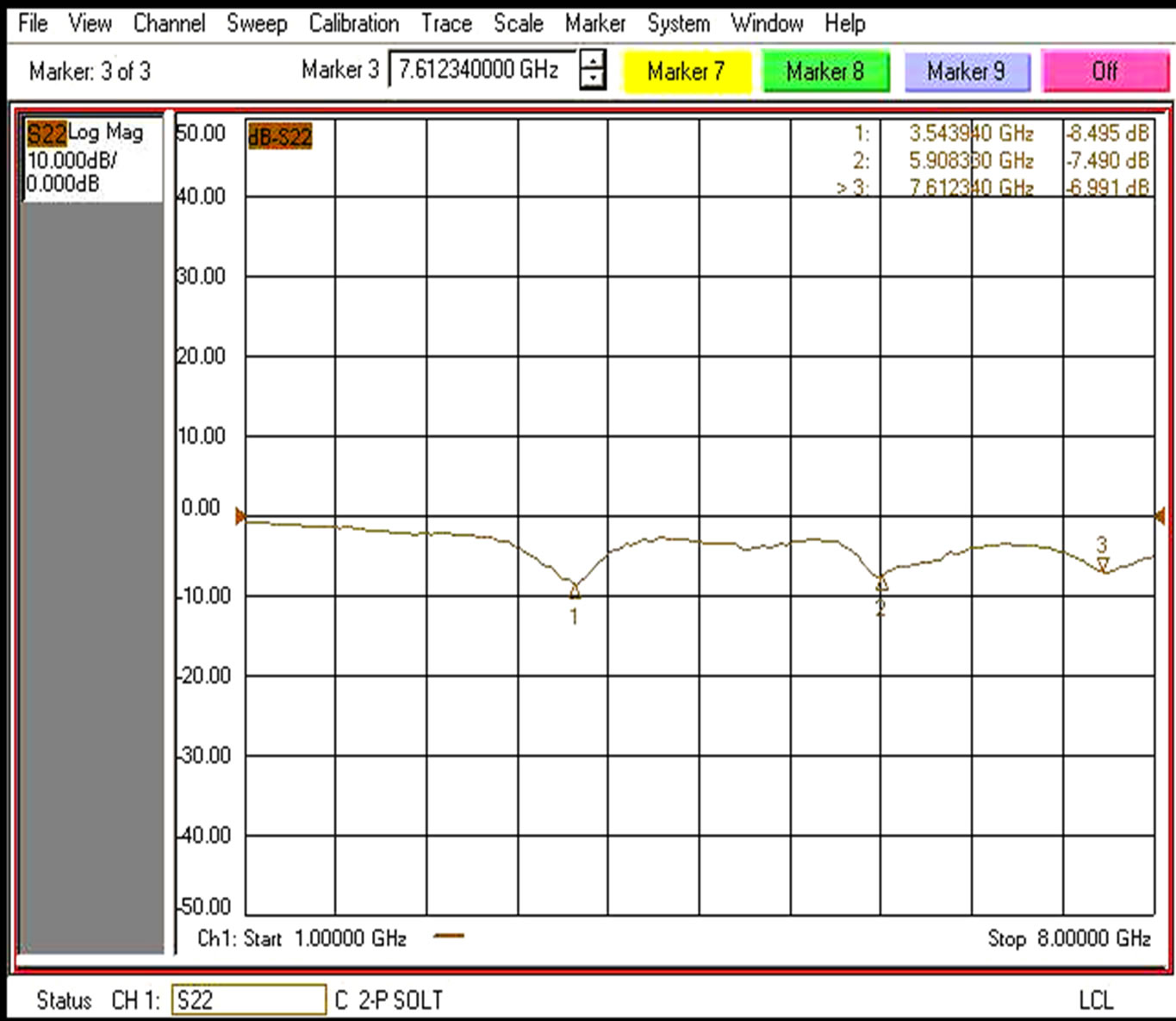 (c)
(c)
Figure 4. (a) The variation of return loss with frequency for aperture coupled microstrip antenna with air gap variation = 2.0 mm; (b) The variation of return loss with frequency for aperture coupled microstrip antenna with air gap variation = 4.0 mm; (c) The variation of return loss with frequency for aperture coupled microstrip antenna with air gap variation = 6.0 mm.
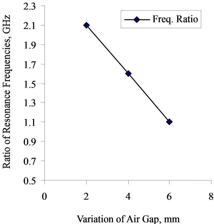
Figure 5. The variation resonance frequency ratio for aperture coupled microstrip antenna with air gap.
4) The variation of resonance frequency ratio f2/f1 with increases the air gap between the single patch and aperture coupled microstrip antenna are decreases. It is shown in Figure 5.
6. Conclusions
This paper has investigated air gap between single patch antenna and aperture coupled microstrip antenna. By using air gap variation between single patch antenna and aperture coupled microstrip antenna is obtained dualband operation. It is observed from experimental results good impedance matching at both resonant frequencies. The overall band width is also achieved 35% of the aperture coupled microstrip antenna. The ratio of resonance frequency ratio is found decreasing (2.1 to 1.6 GHz) with increasing the air gap variation. Therefore the proposed antenna can be used for dual sim mobile application.
7. Acknowledgements
The authors would like to thank Shri R. K. Malaviya of the Space Application Centre, Indian Space Research Organization Ahmedabad, for providing the measurement facilities.
REFERENCES
- I. J. BahI and P. Bharta, “Microstrip Antennas,” Artech House, Boston, 1980.
- D. M. Pozar, “Microstrip Antenna Aperture-Coupled to a Microstripline,” Electronics Letters, Vol. 21, No. 2, 1985, pp. 49-50. doi:10.1049/el:19850034
- K. F. Lee and J. S. Dahele, “Mode Characteristics of Annular-Ring and Circular-Disc Microstrip Antenna with and without Air Gaps,” IEEE Antennas and Propagation Society International Symposium Digest, 1983, pp. 55-58.
- C. S. Lee and V. Nalbandian, “Impedance Matching of Dual-Frequency Microstrip Antenna with an Air Gap,” IEEE Transactions on Antenna and Propagation, Vol. 41, No. 5, 1993, pp. 680-682. doi:10.1109/8.222288
- P. L. Sullivan and D. Schaubert, “Analysis of an Aperture-Coupled Microstrip Antenna,” IEEE Transactions on Antenna and Propagation, Vol. 34, No. 8, August 1986, pp. 977-984. doi:10.1109/TAP.1986.1143929
- D. M. Pozar, “A Reciprocity Method of Analysis for Printed Slot and Slot-Coupled Microstrip Antenna,” IEEE Transactions on Antenna and Propagation, Vol. 34, No. 12, 1986, pp. 1439-1446. doi:10.1109/TAP.1986.1143785
- A. K. Bhattacharyya, Y. M. M. Antar and A. Ittipiboon, “Full Wave Analysis of an Aperture-Coupled Patch Antenna,” Electronics Letters, Vol. 27, No. 2, 1991, pp. 153- 155. doi:10.1049/el:19910099
- C. Wu, K. L. Wu, Z. Q. Bi and J. Litva, “Accurate Characterization of Planar Printed Antenna Using Finite-Difference Time-Domain Method,” IEEE Transactions on Antenna and Propagation, Vol. 40, No. 5, 1992, pp. 526- 534. doi:10.1109/8.142627
- M. Himdi, J. P. Daniel and C. Terret, “Transmission Line Analysis of Aperture-Coupled Microstrip Antenna,” Electronics Letters, Vol. 25, No. 18, 1989, pp. 1229-1230. doi:10.1049/el:19890824
- A. Ittipiboon, R. Oostlander, Y. M. M. Antar and M. Cuchaci, “A Model Expansion Method of Analysis and Measurement on Aperture-Coupled Microstrip Antenna,” IEEE Transactions on Antenna and Propagation, Vol. 39, No. 11, 1991, pp. 1567-1574. doi:10.1109/8.102770
- Z. Aijaz and S. C. Shrivastva, “Effect of the Different Shapes Aperture Coupled Microstrip Slot Antenna,” International Journal of Electronics Engineering, Vol. 2, No. 1, 2010, pp. 103-105.
- G. S. Kirov and D. P. Mihaylova, “Circularly Polarized Aperture Coupled Microstrip Antenna with Resonant Slot and a Screen,” Radio Engineering, Vol. 19, No. 1, 2010, pp. 111-116.
- P. J. Kim, “Optimum Design of an Aperture Coupled Microstrip Patch Antenna,” Microwave Optical Technology Letters, Vol. 39, No. 1, 2003, pp. 75-79. doi:10.1002/mop.11132
- S. C. Shrivastava and Z. Aijaz, “An Introduction of Aperture Coupled Microstrip Slot Antenna,” International Journal of Engineering and Technology, Vol. 2, No. 1, 2010, pp. 36-39.
- Q. Song and X.-X. Zhang, “A Study on Wideband GapCoupled Microstrip Antenna Arrays,” IEEE Transactions on Antenna and Propagation, Vol. 43, No. 3, 1995, pp. 313-317. doi:10.1109/8.372003
- M. Ali, A. Kachouri and M. Samet, “Novel Method for Planar Microstrip Antenna Matching Impedance,” Journal of Telecommunications, Vol. 2, 2010, pp. 131-138.