Smart Grid and Renewable Energy
Vol. 4 No. 1 (2013) , Article ID: 28127 , 4 pages DOI:10.4236/sgre.2013.41008
Efficient Power Conditioner for a Fuel Cell Stack-Ripple Current Reduction Using Multiphase Converter
![]()
Centre for Fuel Cell Technology, ARCI, IIT Madras Research Park, Chennai, India.
Email: *lakshmiraja2003@yahoo.com
Received September 21st, 2012; revised October 31st, 2012; accepted November 6th, 2012
Keywords: Fuel Cell Stack; Ripple Current Reduction; Multiphase Inverter
ABSTRACT
Integration of fuel cell stack with an inverter is complex in nature. A number of factors have to be taken into account in designing the inverter as well as during the integration. One of these factors is ripple current which could affect the life of the fuel cell stack if there is fuel and/or oxidant starvation. In this paper an inverter topology is investigated which significantly reduces or even nullifies the ripple content in the fuel cell system. The investigations have been carried out using indigenously developed 1 KW PEMFC stack and a 4 kW PEMFC stack with single and multi phase inverter. The results are presented here.
1. Introduction
In recent times fuel cells of different types are under active consideration to meet the power needs of a variety of applications owing to a number of their positive characteristics. Fuel cells are electrochemical devices that convert chemical energy to electricity energy with high efficiency. In the case of stationary power applications, electricity can either be directly given to utility with the help of inverters or supply directly in decentralised/stand alone power applications. Fuel cells can also be integrated with DC-DC converters to cater to DC power requirements such as in telecom applications. In spite of the various beneficial features of fuel cell technology, certain challenges still remain, before they can be applied to real world applications. A fuel cell system includes besides the fuel cell stack, a reactants supply system, thermal management and power management system. There are many of challenges in the power conditioning unit (PCU) which vary depending on the application. Conventional inverters used in battery powered UPS systems are not suitable for fuel cell applications as the latter requires an inverter which can accept a large variable input DC voltage (sometimes 1:2) at high current. In addition, by its nature an inverter could impose its own time varying load on fuel cell which would lead to peak currents unsustainable by the fuel cells especially under low reactant conditions [1]. A typical fuel cell PCU employs a switch mode DC-DC and DC-AC converters or direct DC-AC inverter with transformer boost as shown in Figures 1(a) and (b).
In order for low voltage DC fuel cell to generate 120/ 240 V AC at 50/60 Hz, the DC-AC inverter is designed considering the output voltage regulation of the fuel cell stack. The low voltage ac output of the inverter is stepped up using low frequency transformer. The inverter by its nature will draw current from the fuel cell stack twice that of the ac voltage frequency i.e. 100 Hz for 50 Hz ac output system as shown in Figure 2. The ripple current that is experienced by the stack could affect the fuel cell durability.
Chagrong Liu and Jih-Sheng Lai [2] have reported some methods to overcome low frequency ripple current. Woojin Choi et al., [3] have carried out experiments using a commercially available fuel cell stack and the relationship between current and fuel cell stack performance such as power loss and fuel consumption has been investigated. Experimental results indicated that ripple current can contribute up to 10% reduction in the available
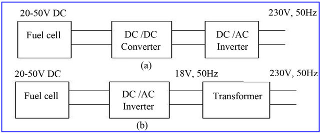
Figure 1. (a) Dc/Dc converter boost; (b) Transformer boost.
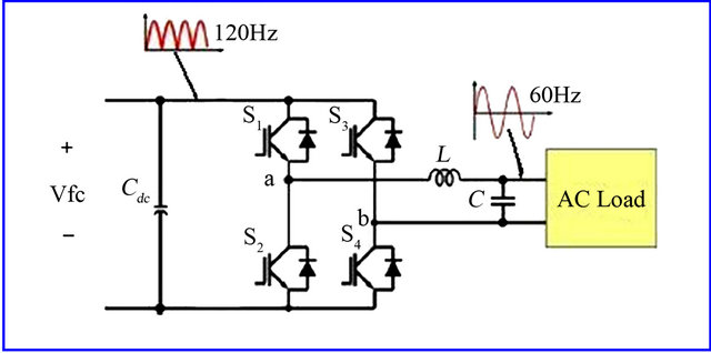
Figure 2. Low frequency ripple current generation by a single phase full bridge inverter [2].
output power. In the present paper we have attempted to reduce the ripple current of the inverter by multiphase interleaving by simulation and validated by experimental results for a fuel cell of 4 kW capacity.
2. Experimental
A transformer based inverter has been used, considering the following important design variables of the PCU like variation of fuel cell terminal voltage from no-load to full load and the maximum ripple current. A large variation in fuel cell terminal voltage from no-load to full load, results in larger volt-amp rating of the PCU. We have carried out various studies using indigenously developed 1 and 4 kW stacks with sine wave inverters, which delivers 220 V AC, 50 Hz and. The 1 kW PEM fuel cell stack consists of 52 cells, delivering a DC voltage was 30 V and the DC current 35 A. The 4 kW stack consisting of 40 cells, the nominal full load output voltage Vfc of the fuel cell stack is 24 V, and the average current Ifc is 165 A. Chauvin arnoux-C.A.8230 power analyzer has been used to measure the voltage, current and ripple content of the inverter power.
3. Results and Discussions
The voltage—current profile of the 1 kW fuel cell stack when integrated with the 1 kVA, 1 Ф inverter is shown in Figure 3. The maxima and minima of the current waveform for various average current along with ripple factor is presented in Table 1. From Figure 3 it can be seen that for delivering a power of 850 W the average current of the fuel cell stack is 27 A. However, since the stack is loaded by inverter the peak current is 42 A. It can also be seen that the current ripple leads to ripple content in the fuel cell stack output voltage due to inherent impedance of fuel cell stack. The “Ripple Factor” which is defined as the ratio RMS value of the ripple content to the dc component is 40% in this case, in which the peak current exceeds the acceptable current limit of the stack, when the stack is operated at its full capacity Based on the above results, the current drawn by a single phase inverter has been simulated, using Pspice for a 4 kW inverter by considering a fuel cell stack delivering a stack output voltage of 25 V at 160 A. If the power were to be delivered by a 1 Ф inverter with typical ripple factor of 40% from the previous results of ripple factor, one can obtain the peak value of the ripple component for a sinusoidal wave, which is 90 A. Hence the maximum current drawn from the stack will be 250 A and the minima will be 70 A, for an average current of 160 A as shown in Figure 4.
In order to reduce the ripple current, two inverters are connected in parallel with an average current of 80 A (@
Table 1. Ripple factor at various stack current.
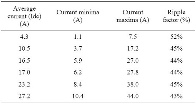
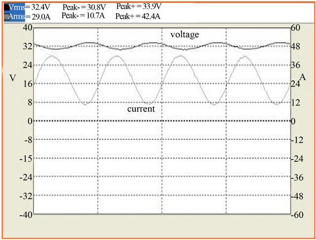
Figure 3. Voltage and current profile of fuel cell stack connected to inverter.
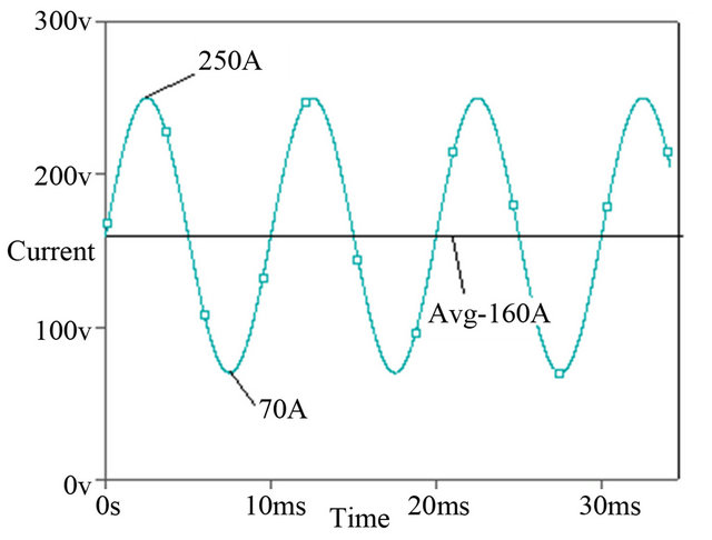
Figure 4. Ripple currents for a single phase inverter.
25 V) each, in order to deliver a total output power of 4 kW. If the two inverters are gated so that the AC output voltage is out of phase by 90˚ (i.e. 2 Φ converters) the current drawn from the stack by each inverter will be out of phase by 180˚ as shown in the Figure 5. Thus the resultant current drawn from the stack will be 160 A without ripple.
Experimental Results
The 2 Ф inverter is integrated with 4 kW fuel cell stack. The inverter is shown in Figure 6. The fuel cell stack is shown in Figure 7.
The fuel cell stack is loaded using the 2 Ф inverter, Figure 8 shows the fuel cell voltage and the current drawn from the fuel cell stack, it can be seen that for average current of 142 A and stack voltage of 30 V the
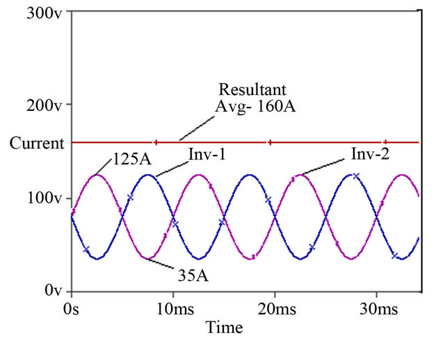
Figure 5. Stack current profile with 2 Φ converters.
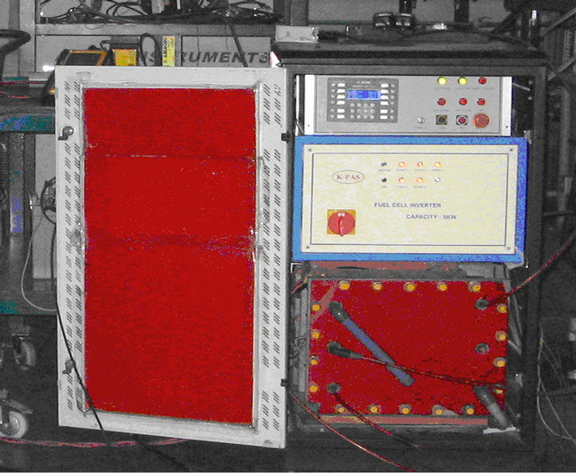
Figure 6. 2 Ф inverter.
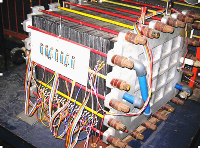
Figure 7. Fuel cell stack.
peak value of current is 150 A. The ripple factor is just 3%. Figure 9 shows the same fuel cell stack connected to 1 Ф inverter loaded to 4.1 kW here we can see that the peak current drawn from the fuel cell is 194 A and the corresponding ripple factor is 32%.
Hence it can be seen that a 2 Ф inverter is highly beneficial in terms of ripple current reduction, thereby saving the fuel cell stack from damage.
4. Conclusion
This paper has investigated ripple generation in fuel cell stack connected to inverter, since it is claimed that ripple current and its corresponding peak current affects the stack performance, 2 Ф inverter is suggested which significantly mitigates ripple current and reduces the peak current imposed on the fuel cell. This also reduces the stack from damage by not drawing excess current than the rated current. This has been simulated and proven experimentally by connecting a fuel cell stack and a 2 Ф inverter and a 1 Ф inverter.
5. Acknowledgements
The authors would like to acknowledge Dr. G. Sundararajan, Director, ARCI for supporting this work. We also
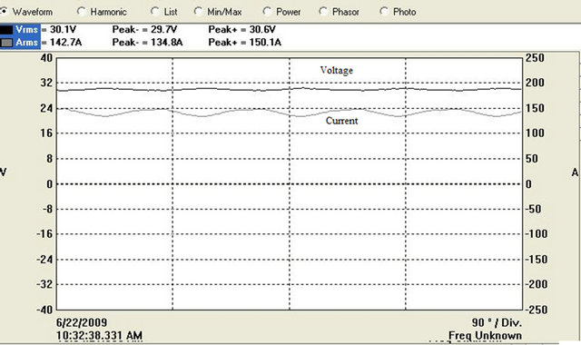
Figure 8. Voltage and current profile of fuel cell stack connected to 2 Ф inverter delivering 4.2 kW.
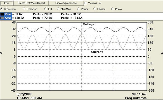
Figure 9. Voltage and current profile of fuel cell stack connected to 1 Ф inverter delivering 4.1 kW.
acknowledge the financial assistance from DST, New Delhi, Government of India.
REFERENCES
- R. S. Gemmen, “Analysis for the Effect of Inverter Ripple Current on Fuel Cell Operating Condition,” Journal of Fluids Engineering, Vol. 125, No. 3, 2003, 10 p.
- C. R. Liu and J.-S. Lai, “Low Frequency Current Ripple Reduction Technique with Active Control in a Fuel Cell Power System with Inverter Load,” IEEE Transactions on Power Electronics, Vol. 22, No. 4, 2007, pp. 1429- 1436.
- W. Choi, P. N. Enjeti and J. W. Howze, “Development of an Equivalent Circuit Model of a Fuel Cell to Evaluate the Effects of Inverter Ripple Current,” 19th Annual IEEE Applied Power Electronics Conference and Exposition, Vol. 1, 27 September 2004, pp. 355-361.
NOTES
*Corresponding author.