Energy and Power Engineering
Vol.5 No.3(2013), Article ID:31252,7 pages DOI:10.4236/epe.2013.53025
A Virtual Synchronous Machine to Support Dynamic Frequency Control in a Mini-Grid That Operates in Frequency Droop Mode
Department of Electrical and Computer Engineering, Concordia University, Montreal, Canada
Email: mi_torre@ece.concordia.ca, lalopes@ece.concordia.ca
Copyright © 2013 Miguel Torres, Luiz A. C. Lopes. This is an open access article distributed under the Creative Commons Attribution License, which permits unrestricted use, distribution, and reproduction in any medium, provided the original work is properly cited.
Received February 28, 2013; revised March 30, 2013; accepted April 12, 2013
Keywords: Frequency Control; Mini-Grid; Inverter; Virtual Synchronous Machine
ABSTRACT
This paper addresses the problem of dynamic frequency control in a diesel-based mini-grid. It is shown that a virtual synchronous machine (VSM) can support dynamic frequency control by adding virtual inertia and damping to the system. However, it is found that the typical formulation of damping power does not work properly when the grid forming gen-set operates in droop mode because of the unknown stabilization value of the grid frequency. As a solution to this problem, an estimator for the stabilization frequency that works in conjunction with the damping function of the VSM is proposed. Theoretical and experimental results provide evidence of a satisfactory performance of the proposed VSM with estimator for different values of the gen-set droop factor. The estimated stabilization frequency converges in approximately 2 s and the maximum frequency deviation during the transient is reduced in 34%, on average.
1. Introduction
Frequency stability is of more concern in “small” power systems, such as mini-grids, where any individual generator in-feed represents a substantial portion of the total demand. The initial rate of change of frequency is typically higher than in large interconnected power systems [1,2] and a lower value of frequency can be reached in a shorter time (for a power increase). In diesel-based mini-grids, frequency is primarily controlled by the grid-forming diesel units. Figure 1 shows the schematic of a supervisory controller of a diesel power plant. Each gen-set presents a primary controller, implemented in the governor, whose main function is to adjust the speed of the gen-set. Since most gen-sets employ a synchronous generator, the governor indirectly controls the frequency of the generated voltage. If the frequency is to be kept constant, an isochronous governor can be used. However, if multiple gen-sets are to operate in parallel, it is more convenient to use a droop based governor where the speed and frequency of a gen-set decrease as its output
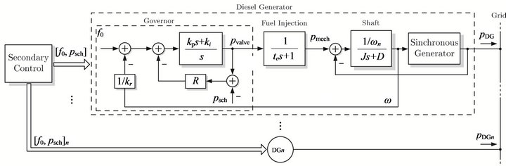
Figure 1. Diesel generator control.
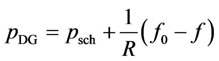
power increases. Besides, operation with variable frequency can be advantageous because it naturally conveys the information of shortage (low frequency) or excess (high frequency) of active power in the mini-grid. This would allow controllable loads, energy storage systems (ESS) and power sources dispersed in the mini-grid to adjust their active power levels accordingly, without the need for a dedicated communication channel [3-5]. The frequency droop characteristic of a gen-set can be represented in steady-state by:
 (1)
(1)
where  is the actual power supplied by the gen-set, f is the grid frequency,
  and
and  are input values that can be set by the secondary control, and
  is the droop factor usually selected so that decreases by about 3% - 5% as varies from no-load to full-load. In the isochronous mode, R is set to 0, meaning that the grid frequency will not change regardless of the output power level.
Frequency stability issues usually appear up to a few seconds following variations in the power demanded from the diesel power plant. They are addressed primarily by the primary frequency control which should make sure that the frequency excursions remain within acceptable values. The secondary control, adjusts the values of  and/or
  to bring the frequency of the mini-grid back to a desired value after the disturbance or to adjust the amount of power provided by each parallel gen-set so as to keep them loaded at safe and more economical levels as computed by an economic dispatch algorithm [5]. However, due to a slower speed of response, the secondary control cannot make a meaningful contribution regarding frequency stability. The supervisory control system of a diesel-based mini-grid can be made very sophisticated, with multiple hierarchical control levels, employing modern information and communication technology [6]. This paper however focuses on frequency stability issues which can be appropriately studied considering only the primary control of the gen-sets.
One important element in the variation of the grid frequency after variations in demand and before the primary controls reactions, is the amount of kinetic energy stored in the rotating masses of the diesel power plant, which tends to reduce the initial frequency rate of change. When a diesel-based mini-grid operates with a reduced number of gen-sets or a high penetration of inertia-less distributed power sources, frequency stability can deteriorate [7]. In this regard, virtual synchronous machines (VSM), which can be defined as inverters that emulate a synchronous generator (SG) or a desired characteristic of it, have been proposed as a solution to address stability issues in power systems with large fraction of inverterconnected distributed generators [8-12]. Most of the reported works on VSMs have focused only on the emulation of inertial response. This paper, however, presents the case of a VSM that also includes the injection of damping power.
The paper is organized as follows. In Section 2 the concept of virtual synchronous machine is introduced and it is shown that when the mini-grid operates in frequency droop mode the typical formulation of damping power does not work properly because of the unknown stabilization frequency of the grid. In order to address this problem, an estimator of the stabilization frequency of the grid is proposed in Section 3 and evaluated theoretically. Then, in Section 4 the performance of the damping function of the VSM in conjunction with the estimator is evaluated experimentally. Finally, the conclusions are presented in Section 5.
2. Concept of Virtual Synchronous Machine
A VSM basically entails the control of the grid-interface converter of a distributed generator or ESS in order to emulate a synchronous generator (SG) or a desired characteristic of it. Figure 2 illustrates the concept of the VSM considered in this work.
The grid frequency (f) is locally measured at the point where the ESS is connected and then, based on the measured frequency, the output power of the VSM  is calculated, which turns out to be the reference for the output active power of the ESS
 . To support dynamic frequency control, the strategy involves emulating two characteristics os a SG that are present only during the transient: the inertial response
  and the damping power
 , with the total output power of the VSM being
 .
.
The inertial response emulates the power that is naturally released or absorbed by a conventional rotating generator as the power demand varies and before its governor reacts. The emulation of inertial response typically entails the generation of a power reference that is
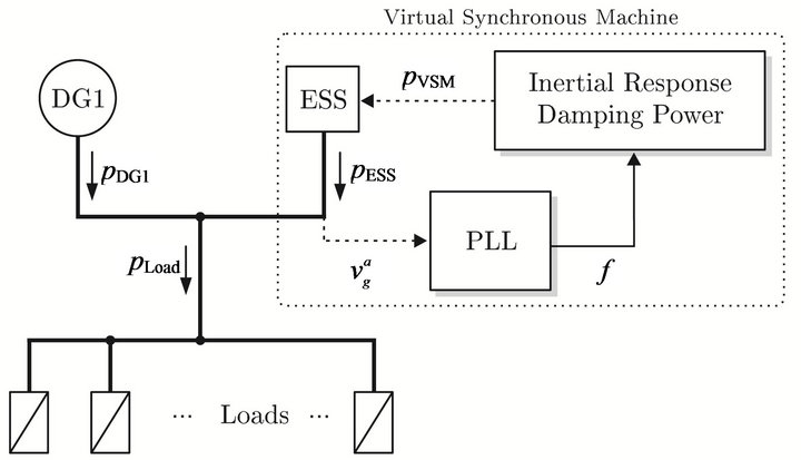
Figure 2. Diesel-based mini-grid with VSM control.
inversely proportional to the first time-derivative of the grid frequency [7,13]. Therefore, when the frequency of the grid starts to decay (a negative derivative), the power converter which is in charge of emulating the inertial response starts to inject power to the grid until the frequency reaches its minimum (when the first derivative is zero), then the frequency starts to increase (a positive derivative) and the converter starts to absorb power. This process will continue until steady-state is achieved. The output power of the VSM due to the inertial response can be defined as:
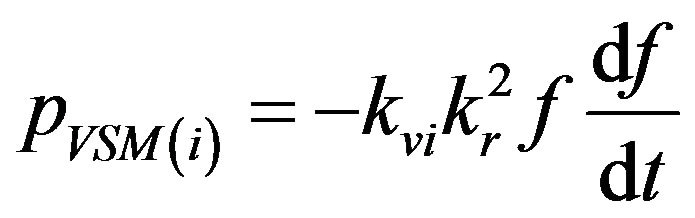 (2)
(2)
where  represents the virtual inertia,
 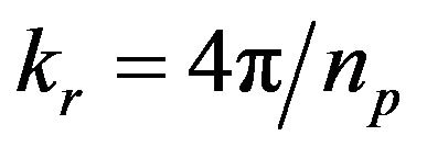 is a constant that relates the electrical frequency with the rotational speed of the VSM, and
  is the number of poles of the VSM. The main effect of adding virtual inertia to the system is that the rate of change of the frequency decreases. However, given that the parameters of the governor(s) remain unchanged and considering that they have been tuned for a specific value of inertia, a side effect of adding virtual inertia is that the frequency oscillates for a longer time after a power disturbance.
The injection of damping power is another function that can be performed by the VSM that helps to stabilize frequency. It is typically calculated as the difference between a reference frequency and the actual frequency of the system as follows:
 (3)
(3)
where  is the damping coefficient and
  is the reference frequency that the system is supposed to reach in steady-state. Any deviation from the reference frequency produces a power that attempts to bring back the grid frequency to the reference, attenuating the amplitude of the oscillations [7,14]. One of the main assumptions in the calculation of the damping power is that the reference frequency, which should be the nominal frequency of the grid, is known. This assumption usually holds true in the case of stiff power systems or mini-grids that operate in isochronous mode, where the value of frequency in steady-state is expected to be fixed (e.g. 60 Hz). However, this might not be the case of mini-grids that operate in droop mode, where the frequency of the grid changes with the load level.
Figure 3 compares the performance of the VSM  in two scenarios: when the gen-set operates in isochronous mode at a nominal frequency of 60 Hz and when the gen-set operates in droop mode with droop coefficient
  Hz/kW (6% droop).
In both cases the gen-set starts in 60 Hz with no load and the load increases in 5 kW at  s. Also, the nominal frequency of 60 Hz is used in both cases as the
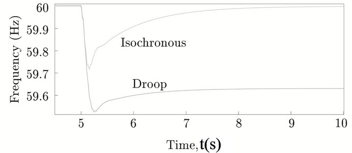
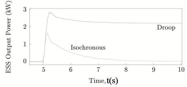
Figure 3. Simulation of the VSM with the gen-set in droop mode. (a) Frequency waveforms; (b) ESS output active power.
stabilization frequency to compute the damping power (3) (as discussed before, it is assumed that the actual stabilization frequency during droop operation is not available for the VSM because it is an internal variable of the gen-set governor). Figure 3(a) shows the frequency waveforms and Figure 3(b) shows the output active power of the ESS. It can be seen that in the case of isochronous operation the output power of the ESS goes to zero as the grid frequency returns to 60 Hz after the transient. In the case of droop operation, due to the assumption  Hz a miscalculation of the damping term occurs, which produces an output power of 2.2 kW for the ESS in steady-state. This continuous output power is considered an undesired behavior of the VSM, whose purpose is to assist frequency control only during the transient. Therefore, in order to inject damping power under frequency droop mode, the reference frequency
  in (3) should follow the stabilization frequency of the grid instead of being a fixed value. In the next section, an estimator of the stabilization frequency is proposed as a solution to provide the reference frequency for the damping function of the VSM.
3. Estimation of the Stabilization Frequency
The proposed estimator consists in a proportional integral (PI) controller with droop factor, which resembles the structure of the speed governor shown in Figure 1. The block diagram of the estimator is depicted in Figure 4, where  is the estimated stabilization frequency,
  is the estimated control error, and
 , are parameters of the estimator. In order to keep the estimator
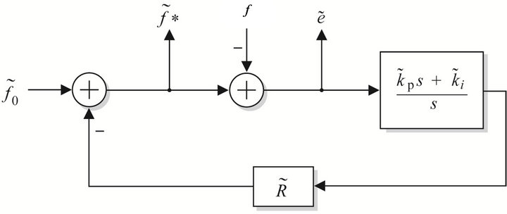
Figure 4. Open-loop estimator.
simple, it has been defined as an open-loop estimator, which means that its performance will depends on how close its parameters are to the actual parameters of the governor. For this reason, a sensitivity analysis is conducted to evaluate the performance of the estimator for different values of its parameters.
Sensitivity Analysis
The sensitivity analysis entails disturbing the system with a step-like load increase of 5 kW and plotting the resulting estimated frequency control error for different values of the estimator parameters. The possible range of variation for each parameter is defined as [0.5, 1.5] pu of its ideal value (the genset actual parameter). The gen-set operates in droop mode (
 Hz/kW), it starts with a load of 20 kW and it is disturbed with a step-like load increase of 5 kW at
  s. The VSM is not connected to the grid. The results for the variation of parameter
  are not shown because it was found that its value acted as an initial bias for
  which was rapidly eliminated by the integrator, therefore affecting only the start-up of the estimator.
Figure 5 shows the results for the variation of the proportional gain while the other parameters remain constant and equal to their ideal values. In the same way, Figures 6 and 7 show the results for the integral gain and the droop factor, respectively. In these three figures, the ideal control error (internal variable of the gen-set governor) is shown in green solid line. In order to evaluate the impact of each parameter on the estimation, the mean absolute error is calculated taking the case when
  and
and  (which is the best performance that the estimator can achieve) as the reference curve. The results are presented in Table 1. It can be observed that the estimation errors are greater when the estimator parameters are, within the range of analysis [0.5, 1.5] pu, below their ideal values and the maximum error is 0.103 Hz which corresponds to a 0.17% of the nominal frequency. The parameter with the highest impact on increasing the estimation error is the droop factor
  whereas the parameter with the lowest impact is the integral gain
 .
.
After evaluating the variation of each parameter inde-
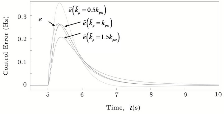
Figure 5. Influence of the proportional gain  on the estimated control error.
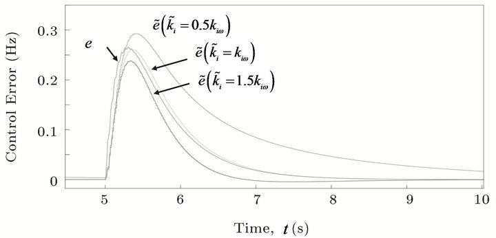
Figure 6. Influence of the integral gain  on the estimated control error.
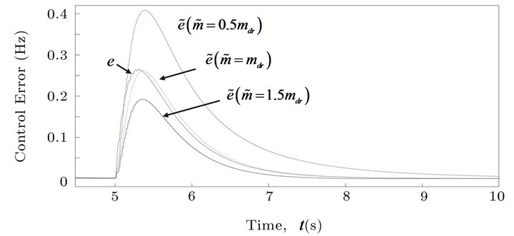
Figure 7. Influence of the droop factor  on the estimated control error.
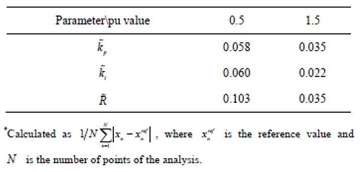
Table 1. Mean absolute errors *(Hz) in estimations of Figures 5-7.
pendently, a case where all the parameters presented deviations from their ideal values was considered. To do this, three coefficients were randomly generated within the range of interest [0.5, 1.5] pu (using the MATLAB command “ ”) and then used to define the parameters of the estimator as:
 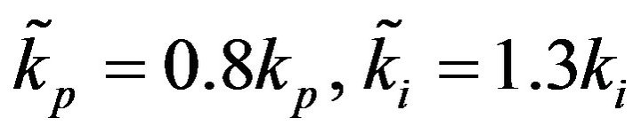 and
and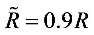 . Figure 8 shows the estimated control error with a mean absolute error of 0.024 Hz, which corresponds to a 0.04 % of the nominal frequency. The relatively low value of this error along with the ones presented in Table 1 demonstrate a satisfactory performance of the estimator.
4. Experimental Results
A schematic of the experimental setup is depicted in Figure 9. An inverter-based emulator [15] is used to represent the diesel generator and the loads are represented by a bank of resistors. The VSM is implemented with a second inverter which is controlled in decoupled power mode [16]. Since only the damping function is evaluated, the reference for the reactive power is set to zero and the reference for the active power is given by (3).
In the first test, the gen-set operates with a droop factor of 6% and the estimator is tuned with the same parameters of the gen-set. The response of the system to a step-like load increase is first obtained with the VSM disconnected from the grid. Then, the VSM is connected to the grid and the load increase is repeated. Figure 10 shows the frequency of the system f and the estimator
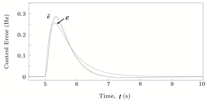
Figure 8. Estimated control error for random variation in parameters.
Figure 9. Experimental setup of the VSM with stabilization frequency estimator.
signals  and
and  for both cases.
A second test is performed to evaluate the performance of the estimator when the droop factor of the gen-set is reduced to 3% while the parameters of the estimator remain unchanged (which was originally tuned considering a 6% droop in the gen-set). As in the previous test, a step-like load increase is produced with the VSM connected and disconnected from the system. Figure 11 shows the frequency of the system f and the estimator signals and  for both cases.
Finally, the droop factor of the gen-set is changed to 0 % while the parameters of the estimator remain unchanged in its original values. As in the previous test, a step-like load increase is produced with the VSM connected and disconnected from the system. Figure 12 shows the frequency of the system f and the estimator signals  and
and  for both cases.
These experimental results support the results obtained in the sensitivity analysis, showing a satisfactory performance of the estimator when the gen-set droop factor is reduced from 6% to 3% and even to 0% (isochronous mode). In all three cases, the estimated control error  converged to zero in approximately 2 s and the VSM was able to effectively reduce the frequency nadir, on average, in 34%.
5. Conclusion
This paper addressed the problem of dynamic frequency
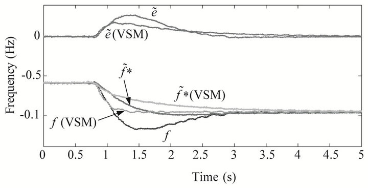
Figure 10. Load increase with gen-set operating with 6% frequency droop.
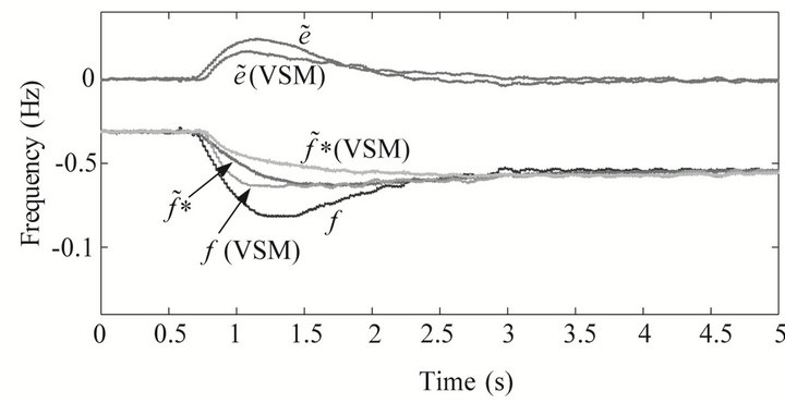
Figure 11. Load increase with gen-set operating with 3% frequency droop.
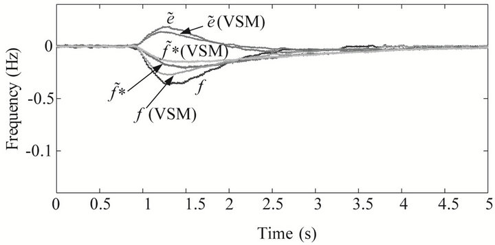
Figure 12. Load increase with gen-set operating in isochronous mode.
control in a diesel-based mini-grid. It was shown that a VSM can support dynamic frequency control (enhance frequency stability) by adding virtual inertia and damping to the system. However, it was also shown that the typical formulation of damping power does not work properly when the gen-set operates in droop mode because of the unknown stabilization frequency of the grid. As a solution, an estimator for the stabilization frequency that works in conjunction with the damping function of the VSM was proposed. Theoretical and experimental results showed a satisfactory performance of the proposed VSM with estimator in reducing the maximum frequency deviation during the transient for different values of the gen-set droop factor.
REFERENCES
- P. Kundur, J. Paserba, V. Ajjarapu, G. Andersson, A. Bose, C. Canizares, N. Hatziargyriou, D. Hill, A. Stankovic, C. Taylor, T. Van Cutsem and V. Vittal, “Definition and Classification of Power System Stability IEEE/CIGRE Joint Task Force on Stability Terms and Definitions,” IEEE Transactions on Power Systems, Vol. 19, No. 3, 2004, pp. 1387-1401. doi:10.1109/TPWRS.2004.825981
- IEEE Std 1159-2009 (Revision of IEEE Std 1159-1995) Recommended Practice for Monitoring Electric Power Quality, IEEE Std., 2009.
- R. Tonkoski and L. A. C. Lopes, “Enhanced Part Load Operation of Hybrid Mini-Grids with High Penetration of Photovoltaics,” 3rd Brazilian Conference on Solar Energy, Belém, 21-24 September 2010.
- K. Elamari and L. A. C. Lopes, “Frequency Based Control of Electric Water Heaters in Small PV-Diesel Hybrid Mini-Grids,” 25th Canadian Conference on Electrical and Computer Engineering, Montreal, 29 April-2 May 2012, pp. 1-4.
- L. A. C. Lopes and M. Dalal-Bachi, “Economic Dispatch and Demand Side Management via Frequency Control in PV-Diesel Hybrid Mini-Grids,” 6th European Conference on PV-Hybrid and Mini-Grids, Chambery, 26-27 April 2012, pp. 266-273.
- F. Katiraei, R. Iravani, N. Hatziargyriou and A. Dimeas, “Microgrids Management,” IEEE Power and Energy Magazine, Vol. 6, No. 3, 2008, pp. 54-65. doi:10.1109/MPE.2008.918702
- J. Morren, S. de Haan and J. Ferreira, “Contribution of DG Units to Primary Frequency Control,” 2005 International Conference on Future Power Systems, Amsterdam, 18 November 2005, p. 6.
- S. De Haan, R. Van Wesenbeeck and K. Visscher, “VSG Control Algorithms: Present Ideas,” 2008. http://www.vsync.eu. Project VSYNC
- K. Visscher and S. De Haan, “Virtual Synchronous Machines (VSGs) for Frequency Stabilisation in Future Grids with a Significant Share of Decentralized Generation,” CIRED Seminar SmartGrids for Distribution, Frankfurt, 23-24 June 2008, pp. 1-4.
- Q. C. Zhong and G. Weiss, “Static Synchronous Generators for Distributed Generation and Renewable Energy,” Power Systems Conference and Exposition, Seattle, 15-18 March 2009, pp. 1-6.
- M. Van Wesenbeeck, S. de Haan, P. Varela and K. Visscher, “Grid Tied Converter with Virtual Kinetic Storage,” PowerTech, 2009 IEEE Bucharest, Bucharest, 28 June-2 July 2009, pp. 1-7.
- Q. C. Zhong and G. Weiss, “Synchronverters: Inverters That Mimic Synchronous Generators,” IEEE Transactions on Industrial Electronics, Vol. 58, No. 4, 2011, pp. 1259-1267. doi:10.1109/TIE.2010.2048839
- J. Morren, S. de Haan, W. Kling and J. Ferreira, “Wind Turbines Emulating Inertia and Supporting Primary Frequency Control,” IEEE Transactions on Power Systems, Vol. 21, No. 1, 2006, pp. 433-434. doi:10.1109/TPWRS.2005.861956
- X. Yingcheng and T. Nengling, “Review of Contribution to Frequency Control through Variable Speed Wind Turbine,” Renewable Energy, Vol. 36, No. 6, 2011, pp. 1671- 1677. http://www.sciencedirect.com/science/article/pii/S0960148110005112 =0pt
- M. Torres and L. A. C. Lopes, “Inverter-Based Virtual Diesel Generator for Laboratory-Scale Applications,” 36th Annual Conference on IEEE Industrial Electronics Society, Glendale, 7-10 November 2010, pp. 532-537.
- T. S. Lee, “Input-Output Linearization and Zero-Dynamics Control of Three-Phase ac/dc Voltage-Source Converters,” IEEE Transactions on Power Electronics, Vol. 18, No. 1, 2003, pp. 11-22. doi:10.1109/TPEL.2002.807145
Appendix
Gen-set model parameters: nominal power = 30 kW, nominal frequency = 60 Hz, 
 Hz/kW (6% droop),
 .
.
Experimental setup: DSP Spectrum Digital ezdspF2812 (control interruption of 10 μs), VSC Semikron Semiteach, VSC output filter parameters: R = 0.2 Ω, L = 32 mH.