Energy and Power Engineering
Vol. 4 No. 3 (2012) , Article ID: 19021 , 7 pages DOI:10.4236/epe.2012.43022
A PID Sliding Mode Control for Ropeless Elevator Maglev Guiding System
Faculty of Electrical and Computer Engineering, University of Tabriz, Tabriz, Iran
Email: hasan.alipour2006@gmail.com
Received March 5, 2012; revised April 12, 2012; accepted April 19, 2012
Keywords: Guiding System; Linear Ropeless Elevator; Non-Linear Control; PID Sliding Mode Controller
ABSTRACT
In this paper, three different controllers are proposed and simulated for maglev guiding systems to have convenient and smooth elevator motion. The proposed controllers are PID, sliding mode, and PID sliding mode controllers. The advantages and disadvantages of the proposed controllers are discussed. Although, PID controller is fast, its response affected considerably by external disturbances. Unlike PID, the sliding mode controller is so robust, but its transient is unsuitable based on application conditions. However, an acceptable controller for ropeless elevator guiding system should guaranty the passengers safety and convenient. Consequently, the response of the system should be fast, robust, and without considerable overshoots and oscillations. These required advantages are compromised in the proposed parallel PID sliding mode controller. The affectivity of the introduced controllers for maglev guiding system is investigated through conducted simulations in MATLAB/Simulink environment. The obtained results illustrate that PID sliding mode controller is a so fast and robust controller for a ropeless elevator maglev guiding system.
1. Introduction
Land in the world’s largest cities is extremely expensive, which drives the expansion of rentable spaces into higher and higher buildings and underground areas. However, the larger and taller the buildings, the more elevators are required to keep acceptable waiting time for dispatching. Ultra high buildings pose new problems in constructing of high speed elevator systems, i.e. vertical oscillations, horizontal swaying, car noise, cable length limitation, and low efficiency [1]. Therefore, conventional elevators with counterweight are improper for skyscrapers. However, ropeless elevators with linear motor propulsion and electromagnetic guiding system can be a proper solution for this problem.
In the conventional elevators, mechanical guiding systems such as slide-ways or rollers are used [2]. However, compared with electromagnetic non-conducted solutions, the conventional lead frame has many disadvantages such as: low efficiency, more deterioration and required frequently lubrication and regular maintenance, more car swaying and audible noise. Particularly, it is important to make the air gap of the linear motor constant, which affects the magnitude of the propulsion force. Therefore, magnetic levitation technologies with electromagnetic actuators are applied to elevators’ guide shoes to restrain the car disturbance and vibration problems. Furthermore, the air gap of elevator linear motors can be adjusted by the guiding system manipulating [3-6].
Electromagnetic actuators are used in a wide field of applications: [7] is proposed an actuator for an axial blood pump, an electromagnetic vibratory actuator for material conveying is shown by [8], or a spherical actuator based on magnetic-dipole-moment principle introduced by [9].
Suspension technologies have brought interesting innovations. The plan-form of non-contact guiding device for a linear elevator is shown in Figure 1.
There are a few studies in the literature about magnetic elevator guiding systems. A fuzzy, fuzzy PI and PID controllers based on feedback linearization are proposed in [2,10,11], respectively. In these studies, just one of the

Figure 1. Linear elevator with non-contact guiding system [2].
counterpart electromagnets is controlled, and the other one produces constant pulling force. However, it is unrealistic and cannot be applicable. A method is proposed in [12] for controlling the ropeless elevator air gaps by manipulating driven double side linear motor normal forces. This controller can handle the car air gap just in one direction. However, composition of this system with electromagnetic guiding system can be promising. A guiding system with five controlled spatial degrees of freedom with implementation of an additional torsion controller is augmented in [4] and [13]. A solution for the design of both the electromagnets and the feedback control of an elevator guiding system is presented in [6]. Also, an elevator test bench for the evaluation of the simulation results is introduced in this paper.
In this paper, a PID sliding mode controller is proposed for ropeless elevator suspension system. The proposed method has robustness and short transient time with low overshoot. Moreover, it is very simple and does not have complex mathematics. Therefore, the proposed method can be easily used for controlling the elevator suspended guiding system in the real applications.
This paper is organized as follows. Mathematics of the system is defined in section 2. A brief review about sliding mode control is discussed in section 3. In sections 4 and 5, A PID controller method is introduced and simulated, respectively. A new application of sliding mode control (SMC) in elevator guiding system is introduced in section 6 and simulation results are illustrated in section 7. A parallel PID SMC method and its simulation results are presented in section 8. Finally, Section 9 concludes the paper.
2. System Definition
A set of hybrid electromagnetic actuators is shown in Figure 2. In this figure, the electromagnets are equipped by permanent magnets (PMs) which provide a magnetic offset. These electromagnets can be energized by two different approaches. In this paper, these methods are named as single side and double side controlling methods.
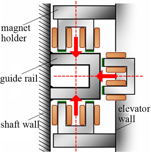
Figure 2. A set of hybrid electromagnetic guiding system [4].
In the single side controlling method, one of the counterpart electromagnets is energized permanently by a constant current or replaced by a PM. Therefore, the current of the other electromagnet is controlled for placing the elevator car in the proper position [10]. This method does not seem so attractive, because of considerable permanent currents in the electromagnets and consequently, relative high-power losses.
In the other method, both of counterpart electromagnets can be energized by a variable current. In this paper, a new controller based on PID and sliding mode controllers is proposed for double side elevator guiding system.
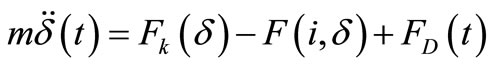
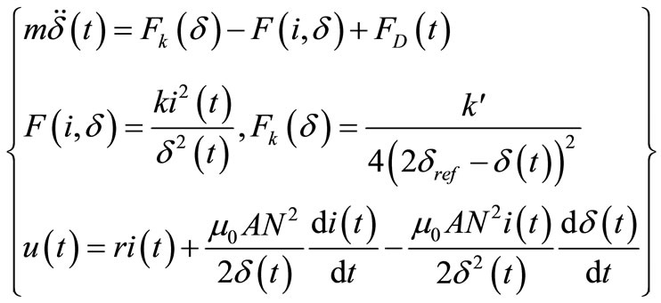
According to Newton’s second law, dynamic equation of a single side guiding system is as Equation (1).
 (1)
(1)
where δ,  , F(i,δ), Fk(t), and FD(t) are the air gap length, second differential of the air gap, electromagnetic force, electromagnetic force of the opposite actuator with constant current or PM, and external disturbance force, respectively.
Since the magnetic resistances of the electromagnets and guiding rail are negligible, the reluctance of the magnetic circuit composes of the electromagnets and guiding rail is focused on the air gap between them. Therefore, the effective air-gap reluctance is as follows:
 (2)
(2)
where μ0 and A are permeability of the vacuum and cross section of the air gap, respectively. Consequently, the pulling force is calculated as Equation (3).
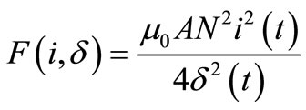 (3)
(3)
where N and i(t) are the number of winding turns and the current of single guiding equipment, respectively.
Voltage of single guiding equipment is:
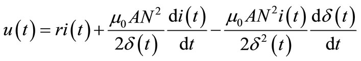 (4)
(4)
Consequently, mathematical model of single electromagnetic equipment system is obtained as follows:
 (5)
(5)
where, k = (μ0AN2)/4, δref is reference value for δ, and k' is a constant coefficient which depends on the current of the counterpart electromagnet or characteristics of the PM.
Equation (6) illustrates that the control system can be more complicated by voltage controlling. Therefore, in this paper, current signal is chosen as control input.
In the double side controlling method, the counterparts of the guiding system can be controlled simultaneously. Therefore, dynamic model of the guiding system is corrected as Equation (6).
 (6)
(6)
3. Sliding Mode Control Definition
SMC is a nonlinear control method which can control a system even when there is not accurate mathematical model. Obviously, controlling a system with one degree is simpler than a system with n-degrees. Hence, SMC method tries to control an n-degrees system by manipulating its one-degree representative system. This agent system is named sliding surface [14].
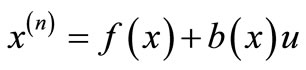
Assume that dynamic of a nonlinear system can be formed as Equation (7).
 (7)
(7)
where x, and u are state variable and control input vectors, respectively.
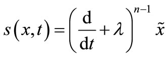
A sliding surface should be defined for controlling this system. Sliding surface can be defined in various forms such as Equation (8).
 (8)
(8)
is an error vector such as Equation (9), and λ is a constant parameter which confines the steady state's errors.
 (9)
(9)
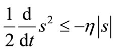
Error value converges to zero, If s(x,t) is stabled in zero. This convergence is guaranteed if Equation (10) is satisfied.
 (10)
(10)
Reaching time on the zero-surface is regulated by η such as Equation (11).
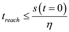 (11)
(11)
Consequently, controlling a system with n-degrees is converted to control of sliding surface. The SMC effect consists of two parts: one part is equivalent control effect; the other one is switching control effect. Certainties of the system are controlled by equivalent control effect. On the other hand, uncertainties of the system are controlled by switching control effect. Thus, this system has strong robustness [15].
Equivalent effect of the SCM can be attained by deriving from sliding surface. Differential of s(t) should be maintained on zero by proper input signal selection. Furthermore, a switching term for uncertainty controlling is added to the system input signal, as:
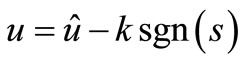 (12)
(12)
where, u is the control input of the system,  is a control signal for certainties of the system, k is switching coefficient, and sgn(s) is sign function that is defined as:
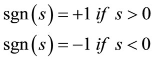 (13)
(13)
Therefore, if Equations (10) and (12) are satisfied, s(t) is stabled and converged.
4. A PID Controller for Ropeless Elevator Guiding System
In this paper, currents (i1, i2) are applied instead of applying a voltage signal as a reference control value to the guiding system. Moreover, if we assume that two counterpart electromagnets cannot be simultaneously energized, the problem becomes simpler. In other words, the output of a PID controller, which is used to control the amount of air gaps in the reference value (δref), is applied to the system according to Equation (14). The guiding system with PID controller is shown in Figure 3. Since the current and guiding force is directly controlled, the system has suitable stability, in this case.
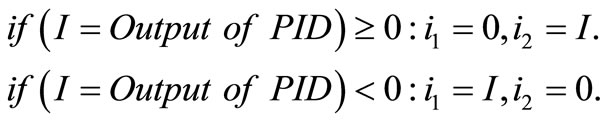 (14)
(14)
5. Simulation Results for Elevator Guiding System with PID Controller
The efficiency of the introduced PID controller is investigated through conducted simulations in MATLAB/Simulink environment. The parameters of the elevator guidance system are illustrated in Table 1.
An external pulsed disturbance force is applied to the system as Figure 4. Moreover, the considered values for PID parameters (KP, KI, and KD) are 5000, 2000, and 20, respectively. In these conditions, the resulting air gap variation of the guiding system is shown in Figure 5. Obviously, the position of the elevator car is disturbed
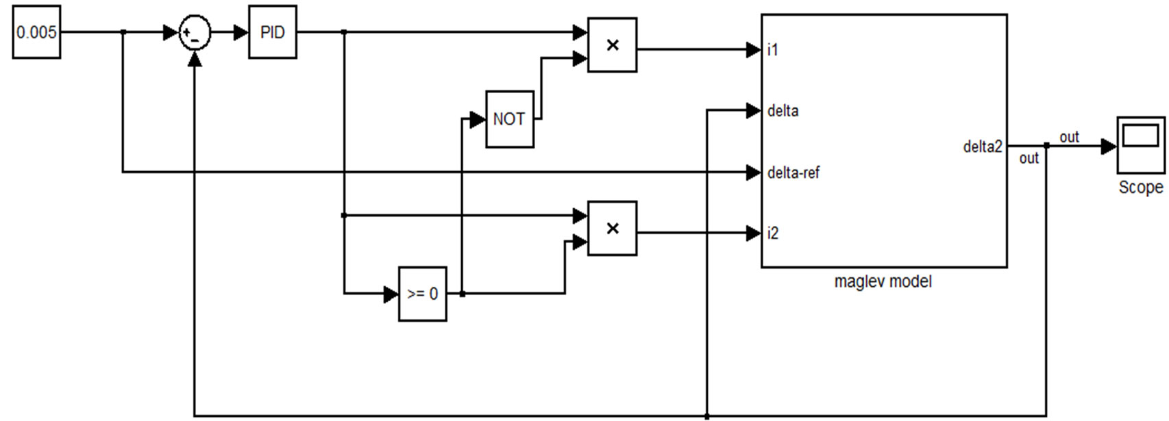
Figure 3. Double elevator guiding system with PID controller.
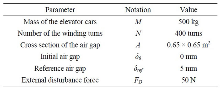
Table 1. parameters of the ropeless elevator guidance system.
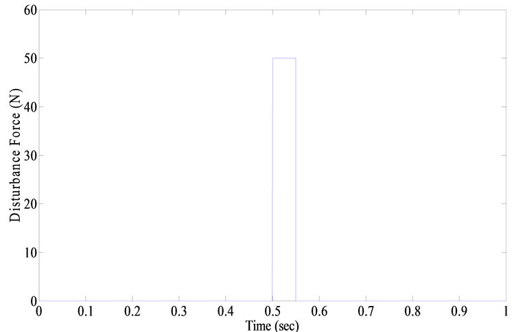
Figure 4. External disturbance force (FD(t)) for PID controller.
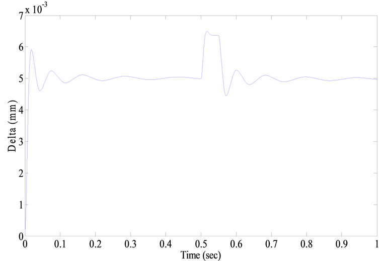
Figure 5. Simulation result for air gap of the PID controlled system.
considerably by influence of the external disturbance force. However, using fuzzy PID controllers or a PID controller with lookup table and various parameters can lead to a more robust system [16]. The input currents of the counterpart electromagnets are shown in Figure 6.
6. A Sliding Mode Controller for Ropeless Elevator Guiding System
Accuracy of a ropeless elevator guiding system has a major role in safety and convenience of the passengers, and reduction of horizontal swaying and car noise. Therefore, a more robust controller than the simple PID is necessary. SMC is a very robust controller and can have suitable compatibility with nonlinear nature of elevator guiding system dynamics.
Assuming that the currents of counterpart electromagnets are not independent, and they cannot be energized simultaneously, Equation (6) is rewritten as Equation (15). Therefore, the system equation can be considered as Equation (7).
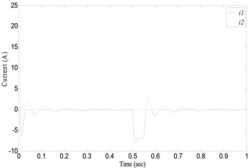
Figure 6. Input currents of the electromagnet of the PID controlled system.
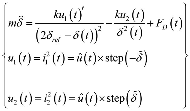 (15)
(15)
where, step(x) is equal to 1 if x has positive value, otherwise it will be zero.
For this problem, an integrated function of error is chosen as a sliding surface as Equation (16).
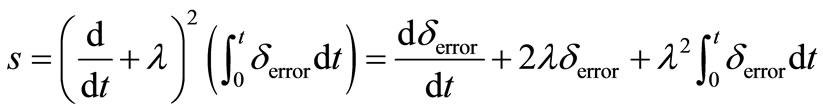 (16)
(16)
where, δerror is difference between δref and δ(t), supposing that δref has a constant value.
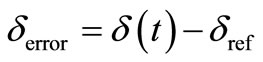 (17)
(17)
The value of sliding surface in the stable condition must be constant. Therefore, the differential of s(t) should be equal to zero. Consequently, considering on Equations (16) and (17), ds/dt can be written as Equation (18).
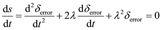 (18)
(18)
Finally, substituting d2δ(t)/dt2 from Equation (15) in Equation (18) results Equation (19).
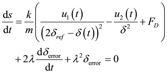 (19)
(19)
In this method, input signal has two parts. One part controls the certainty of the system, and the other one is a switching signal that is adjusted to uncertainty of the system. Solving Equation (19) by considering Equation (15), first term of the control signal is achieved as Equation (20). Therefore, the control signal of the system is expressed as Equation (12).
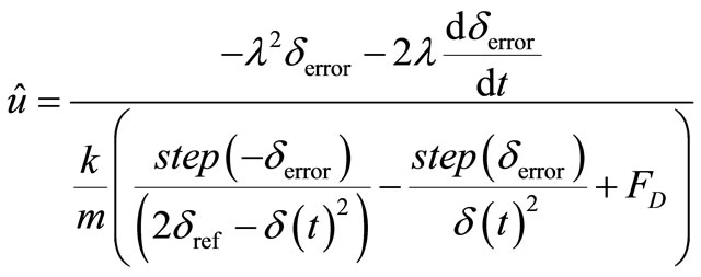 (20)
(20)
7. Simulation Results for Sliding Mode Controller
Parameters of the system are assumed as Table 1. For having a realistic system, the input current is limited to 0 to 12 amperes. Furthermore, an external disturbance force is applied Figure 7. The simulated air gap and input currents of the guiding electromagnets are shown in Figures 8 and 9, respectively. The results illustrate that the proposed method is more robust against disturbances; however, it has unsuitable and long initial transients.
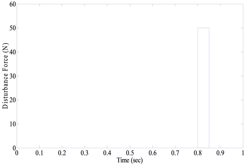
Figure 7. External disturbance force for SMC controlled system.
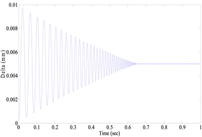
Figure 8. Simulation result for air gap of the SCM controlled system.
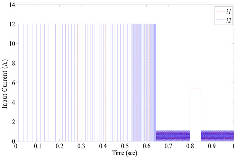
Figure 9. Input currents of the electromagnet of the SCM controlled system.
8. A PID SCM Controller and Simulation Results
An acceptable controller should have suitable transient and robustness. Therefore, a combination of PID and sliding mode controllers with limited input current, which may have both advantages, is more acceptable.
In this paper, a parallel PID SMC controller is proposed. In other words, the transient part of the system is controlled just by PID. Then, after the rise time of the system response, the controller is switched to SMC.
The simulation results for the proposed controller are shown in Figures 10 and 11. In this test, a 50N-pulsed external disturbance is applied to the system between 0.2 and 0.25 seconds. The response of the external disturbance is zoomed in Figure 12. Consequently, results illustrate that the proposed controller is a robust controller with a suitable transient.
9. Conclusions
In this paper, three new control methods are proposed for ropeless elevator guiding system. These methods are
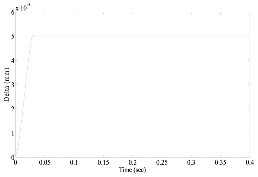
Figure 10. Simulation result for air gap of the PID SCM controlled system.

Figure 11. Input currents of the electromagnet of the PID SCM controlled system.
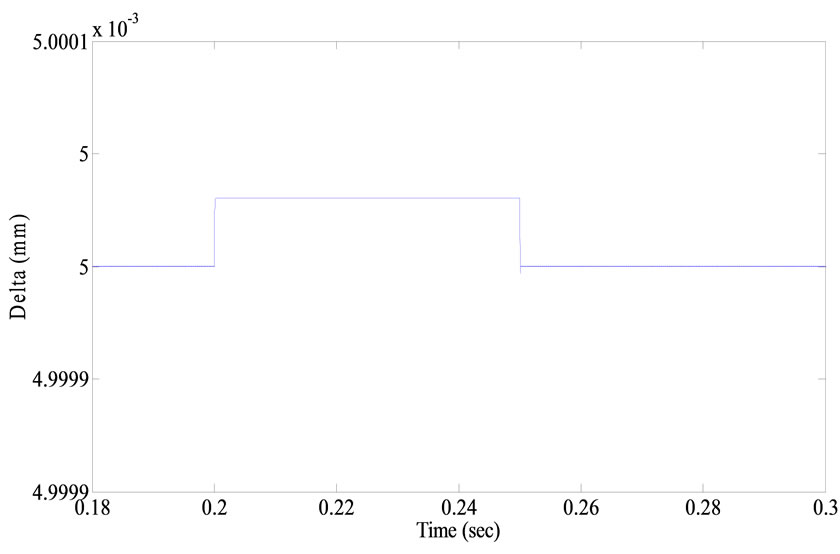
Figure 12. Zoomed air gap of the PID SCM controlled system.
very simple and applicable. The PID controller has acceptable inertial transient, but it is not a robust controller. The proposed sliding mode controller is so robust. However, its response has long and unsuitable transients.
Since guiding system of a linear ropeless elevator has an important role in passengers’ safety and convenient, the controller should be robust with an acceptable transient. Hence, the PID SMC controller is proposed. This controller has proper balances between these properties. The performances of PID SMC controller has been verified by simulation results.
REFERENCES
- J. F. Gieras, Z. J. Piech and B. Tomczuk, “Linear synchronous motors, transportation and Automation Systems,” 5th edition, CRC Press, Boca Raton, 1999.
- D. m. Yu, M. l. Hao and H. Liu, “Fuzzy control of Maglev Guiding System in Liner Elevator Based on Feedback Linearization,” 30th Chinese Control Conference, Yantai, 22-24 July 2011, pp. 2899-2902.
- K. Davey, “New Electromagnetic Lift Control Method for Magnetic Levitation Systems and Magnetic Bearings,” IEEE Transactions on Magnetics, Vol. 40, No. 3, 2004, pp. 1617-1624. doi:10.1109/TMAG.2004.827189
- B. Schmulling, O. Effing and K. Hameyer, “state control of an Electromagnetic Guiding System for Ropeless Elevators,” European Conference on Power Electronics and Applications, Aalborg, 2-5 September 2007, pp. 1-10. doi:10.1109/EPE.2007.4417287
- B. Schmulling, R. Appunn and K. Hameyer, “Electromagnetic guiding of Vertical Transportation Vehicles: State Control of an Over-Determined System,” 18th International Conference on Electrical Machines, Vilamoura, 6-9 September 2008, pp. 1-6. doi:10.1109/ICELMACH.2008.4800171
- R. Appunn, B. Schmulling and K. Hameyer, “Electromagnetic Guiding of Vertical Transportation Vehicles: Experimental Evaluation,” IEEE Transactions on Industrial Electronics, Vol. 57, No. 1, 2010, pp. 335-343. doi:10.1109/TIE.2009.2032432
- S. M. Yang and M. S. Huang, “Design and Implementation of a Magnetically Levitated Single-Axis Controlled Axial Blood Pump,” IEEE Transactions on Industrial Electronics, Vol. 56, No. 6, 2009, pp. 2213-2219. doi:10.1109/TIE.2009.2017095
- Z. V. Despotovic and Z. Stojiljkovic, “Power Converter Control Circuits for Two-Mass Vibratory Conveying System with Electromagnetic Drive: Simulations and Experimental Results,” IEEE Transactions on Industrial Electronics, Vol. 54, No. 1, 2007, pp. 453-466. doi:10.1109/TIE.2006.888798
- C. K. Lim, I. M. Chen, L. Yan, G. Yang and K. M. Lee, “Electromechanical Modeling of a Permanent-Magnet Spherical Actuator Based on Magnetic-Dipole-Moment Principle,” IEEE Transactions on Industrial Electronics, Vol. 56, No. 5, 2009, pp. 1640-1648. doi:10.1109/TIE.2008.2009526
- H. Qing, H. Mingliang and L. Hao, “Fuzzy PI control of Maglev Guiding System Based on Feedback Linearization,” Chinese Control and Decision Conference, Mianyang, 23-25 May 2011, pp. 1213-1216. doi:10.1109/CCDC.2011.5968372
- H. Qing, L. Hao and O. Lisheng, “Fuzzy PID Nonlinear Control of Maglev Guiding System for Linear Elevator Based in Feedback Linearization,” 7th International Conference on Fuzzy Systems and Knowledge Discovery, Yantai, 10-12 August 2010, pp. 1277-1280. doi:10.1109/FSKD.2010.5569119
- T. Sakamoto and Y. Noma, “Guidelines for VSS controller design of LSM-driven Ropeless Elevator,” IEEE International Symposium on Industrial Electronics, Seoul, 5-8 July 2009, pp. 1564-1568. doi:10.1109/ISIE.2009.5215938
- B. Schmülling, P. Laumen and K. Hameyer, “Improvement of a Non-Contact Elevator Guiding System by implementation of an Additional Torsion Controller,” IEEE Energy Conversion Congress and Exposition, Atlanta, 12-16 September 2010, pp. 2971-2976. doi:10.1109/ECCE.2010.5618232
- E. S. Jean-Jacques and W. p. Li, “Applied Nonlinear Control,” Prentice Hall, Upper Saddle River, 1991.
- X. Zhang, H. y. Yu and H. Liu, “A Novel Control for Linear Elevator Based on Reference Model Sliding Model,” IEEE International Conference on Automation and Logistics, Shenyang, 5-7 August 2009, pp. 734-737. doi:10.1109/ICAL.2009.5262828
- M. B. B. Sharifian, H. Afsharirad and S. Galvani, “A Particle Swarm Optimization Approach for optimum Design of PID controller in Linear Elevator,” International Power and Energy Conference, Singapore, 27-29 October 2010, pp. 451-455. doi:10.1109/IPECON.2010.5697038