Communications and Network
Vol.5 No.3(2013), Article ID:35661,8 pages DOI:10.4236/cn.2013.53028
Losses in Wireless ATM Networks
Department of Electrical Engineering, Faculty of Engineering Technology, Albalqa Applied University, Amman, Jordan
Email: harasis.hasan@yahoo.com
Copyright © 2013 Hasan Harasis. This is an open access article distributed under the Creative Commons Attribution License, which permits unrestricted use, distribution, and reproduction in any medium, provided the original work is properly cited.
Received April 16, 2013; revised May 16, 2013; accepted June 16, 2013
Keywords: ATM; QoS; STH; Handover
ABSTRACT
The standardized approach to Mobile ATM network handover is a hard backward or forward handover scheme with no guarantees for the integrity of the data stream. These handover functions are detailed in this paper and a more performant virtual connection handover protocol, using in-slot signaling techniques in order to facilitate loss less handover, is introduced. The QoS aspects related to this scheme are discussed and its OAM implementation is presented.
1. Introduction
The broadband service requirements for future generations of mobile communications can be accommodated also by high bandwidth ATM networks. However, ATM is developed for fixed networks and mobility management functionality has to be added to the traditional set of capabilities. Mobile or Wireless ATM consists of two major components: the radio access part which deals with the extension of ATM services over a wireless medium and the mobile ATM part which addresses the issue of enhancing ATM for the support of terminal and service mobility in the fixed portion of the WATM network. Wireless ATM starts as a technology designed to be used for LAN or fixed wireless access solutions, where low mobility constraints are encountered. Further research projects and standardization activities coordinated by the ATM Forum demonstrate the feasibility of broadband radio access networks based on ATM technology, which can offer full-scale mobility together with all the range of ATM service capabilities existent also in the fixed ATM networks [1].
The frequency-domain supposed to be used for Mobile ATM, situated in the GHz range, will imply the existence of small size cells, and this will result, in conjunction with a higher terminal mobility, to a very large number of handovers of virtual connections. The more complex handover procedure has higher requirements regarding radio resource management functions for the air interface paired with network signaling and control functions for handover control, Quality of Service (QoS) management and rerouting of the connection to the new network access point. The standardized approach to Wireless ATM network handover is a hard backward or forward handover scheme with no guarantees for the integrity of the data stream [2]. In order to cope with the requirements of future multimedia applications, more complex solutions, which are also including options for QoS control, are needed. These handover functions of a Mobile ATM network are detailed in this paper and a more performant handover protocol, using in-slot signaling techniques in order to facilitate lossless handover, is presented.
2. Mobile ATM Network Architecture
One standard reference scenario for Mobile ATM contains a broadband wireless access system providing unrestricted roaming capabilities within a certain area of continuous radio coverage as shown in Figure 1. The base stations (Radio Access Point, RAP) are of picocellular size and implement the physical transport medium, multiple access control, data link control and basic radio resource management capabilities. The RAP does not necessarily have to provide ATM-based physical transport, it could use as well any other access technology, as for example CDMA, also because the error detection and correction capability of the ATM stack is typically low, since it was designed for a reliable network. For this paper, we assume though the existence of an ATM radio interface capable of transmitting ATM cells over the wireless medium. Special Mobile ATM Switches (MAS) are positioned at the border of an ATM network, supporting end-system mobility by possessing the necessary extensions in the signaling and control planes to provide func-
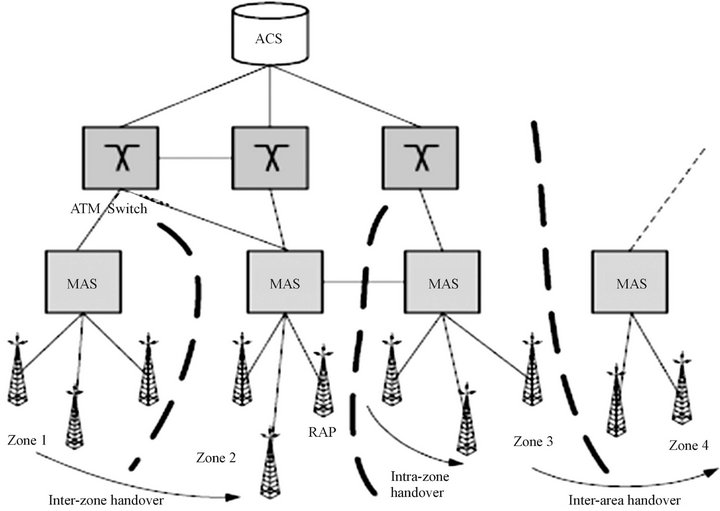
Figure 1. Architecture of the Wireless ATM network.
tions for mobility management and also connection handover.
All the RAP’s associated with a particular MAS form a so called zone of continuous coverage. Terminal mobility inside a certain zone and the handover associated with it (intra-zone handover) is handled locally by the MAS itself. Neighboring zones with uninterrupted radio coverage can form an area in which, at any time, a RAP can be found to hand a connection over to, while the terminal is moving without restrictions. The size of such an area is not limited, it could take the size of the entire network.
It is not mandatory that all the switches should be able of supporting end-system mobility, therefore we introduce an hierarchically superior instance, called Area Communication Server (ACS), providing mobility control for a specific area. The ACS represents a mobility supporting ATM switch in charge of processing the protocol requests in case of an inter-zone handover. It also serves as Anchor Point (AP) for the active connections of the terminals inside this area. By using the ACS, the impact of the end-system mobility on the network can be significantly reduced, because there is no need anymore for mobility specific functionality outside the ACS area. The disadvantage consists in the fact that connectivity cannot be guaranteed for terminals leaving this area.
A consequence of the high mobility of the terminals is the requirement of a permanent reestablishment of the virtual connection, in order to reach their current point of access to the network. This implies, beyond signaling and handover control, a process of rerouting of the connection in the ATM network. QoS control based on requirements coming from the connection itself has to be provided in order to ensure the lossless and in-sequence delivery of the ATM cells during the handover process.
3. Handover Functions of a Mobile ATM Network
Several different handover protocols have been described in the literature [3-7]. Based on the number of simultaneously active radio connections, one can distinguish between two main streams in the handover techniques: the hard handover and the soft handover. In the case of the hard handover, it always exists only one active radio connection and the handover control flow can be directed either across the current RAP’s air interface (backward handover) or across the target RAP’s air interface (forward handover). The soft handover tries to eliminate the disadvantage of the hard handover, consisting of the interruption of the data stream during the connection switch over, by establishing and activating a second radio connection to the target RAP. The areas covered by the Mobile ATM handover techniques so far are presented in Figure 2.
Until now, no WATM handover mechanisms which allow forward handover and, at the same time, maintain
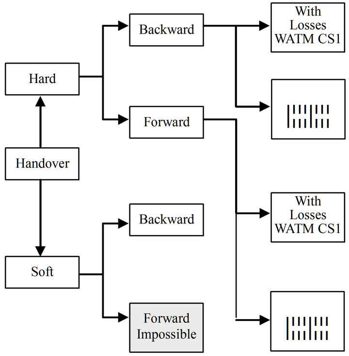
Figure 2. Mobile ATM handover schemes.
cell loss QoS guarantees, have been proposed. Nevertheless, future Mobile ATM systems will demand the flexibility and robustness in handover control as well as an increase in QoS.
Soft handover is considered to be the handover solution of future wireless network systems, the so called 4G or Next Generation Mobile Systems. During a soft handover process, the MT is able to communicate simultaneously with both RAP’s. Therefore, each connection possesses two active mobile segments between the MT and the COS. There are several known methods, developed for the fixed ATM networks, able to establish cell synchronicity between two different paths [8-10]. Cell synchronicity is mandatory for an adaptive and latency free switching between the two paths, achieving by this a quality gain (macrodiversity). The periodical in-slot signaling procedure upon which the lossless handover scheme proposed in this article is based, is also suited to synchronize the two paths, as it has been described in the Alignment Server Method [8,9].
4. A Lossless Handover Scheme
During the handover of virtual connection there are some situations when errors occur [10]. These errors cause on the downlink the loss of in transit cells due to forced handover decisions and they can also cause on the uplink disruption of ATM cell sequence at the handover Cross Over Switch (COS) due to a transfer delay mismatch between the old and the new path as shown in Figure 3.
The result of the cell loss is a degradation of the QoS of a virtual circuit connection by affecting the data stream integrity. Several methods, based on an in-band signaling approach with two-way handshake, for preventing cell loss and disruption have been described in
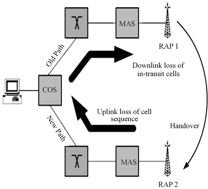
Figure 3. VC-Handover, error scenarios.
the literature [11-13]. Their advantage consists in their relative simplicity which easies the implementation. Their main disadvantage comes up in the case of a single signaling cell loss or in emergency handover situations, when the mobile looses the connection to the old cell before the signaling cell reaches him.
The procedure proposed in this paper called Sync-TagHandover (STH) is dealing with these aspects, being therefore more robust. The way this algorithm works is shown in Figure 4: the COS inserts periodically into the downlink ATM cell stream in-band signaling cells containing a tag, carrying sequential numbering information. The mobile terminal sends these tags back as an acknowledgment receipt for the correctly received segments of the downlink cell stream. At transmission, each cell stream segment is also copied into a retransmission buffer inside the COS and deleted out of this buffer when the receipt was received. At handover, the mobile terminal is sending an End-of-Line signal in the uplink direction, is performing the handover and resending with the new RAP by sending it the number of the last tag correctly received on the downlink from the old RAP. By this, the COS knows that it has to start retransmitting the content of the buffer starting with the tag-number just mentioned, to the new RAP. The STH scheme is designed to flexibly support both handover variants: backward handover and forward handover. This handover scheme enables the mobile station to instantaneously detach from its current RAP and hand over its connection to the target RAP at any time. As during backward handover the handover signaling is exchanged with the old RAP, this instantaneous detach facility of STH is of no particular use in this case. But it can be very successfully exploited to provide zero cell loss forward handover. In the forward handover case, the control message flow
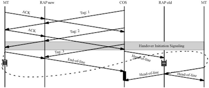
Figure 4. Principle of Sync-Tag-Handover STH.
will be routed across the new RAP after the MT successfully attached itself. Because of the periodic insertion of sequence numbers and buffering of not yet confirmed cell stream segments in the COS, there is no need to perform an in-slot signaling handshake before the handover to enforce zero cell loss.
The MT can abruptly detach from the failing link’s RAP, while at the same time maintaining state information to facilitate a zero cell loss handover. Cell sequence information and retrains-mission buffer are concurrently kept up to date and can be readily evaluated for the cell stream resynchronization after the successful attach at the new RAP and the rerouting decision in the ACS!COS.
Should the connection’s QoS contract require zero cell loss during handover, the buffering mechanism will allow ATM cells otherwise lost (i.e. at most those not yet acknowledged by an uplink tag) to be forwarded by the COS to the new RAP. The mobile terminal will then use the stored numbering information to resynchronize the ATM cell stream just as in the backward handover case.
In a WATM system, soft handover macro diversity calls for ATM cell level synchronization of two communication paths between MT and ACS!COS. Each path carries the same user data stream, but displays possibly different delay properties. Therefore, synchronization between the two cell streams is mandatory and once this state has been reached, it is possible to dynamically select the best path, on a per cell stream segment or even on a per cell basis. Synchronization and dynamic path selection takes place in the ACS!COS for the uplink direction and in the MT for the downlink direction. STH as basic handover protocol is prepared to support cell level synchronization for this dual cast situation with minimal extensions. The in-slot signaling mechanism already provides means for synchronizing the two communication paths over the different RAPs. Whereas this synchronization is used to protect cell sequence and prevent cell duplication in the hard handover case, it can be directly applied to synchronize two continuous ATM cell streams during the soft handover phase. Once a soft handover situation has been detected and path diversity has been established by activating a second radio link to the handover candidate RAP, the COS will start dual casting the downlink cell stream on both paths. Using the in-slot numbering information, the MT is able to synchronize these two paths and to dynamically select one path on a per cell stream segment basis. The in-slot tag completing the selected cell stream segment is then looped back on both uplink diversity paths. This enables the COS to also activate its dynamic path selection algorithm. Once the radio conditions are sufficiently stable to guarantee reliable communication via the new RAP, dual casting can be terminated and the handover completed. Soft handover is highly resource intensive in terms radio frequency spectrum and cell transport bandwidth. On the other hand, STH based soft handover does not rely on cell segment retransmission and therefore does not require any retransmission buffering space in the COS. The only buffering space required is a small path synchronization buffer in MT and COS. Moreover, soft handover provides the best QoS performance of all handover alternatives. The old and the new path are synchronized on the ATM cell level, facilitating path selection and therefore handover switching/connection rerouting in real-time without introducing any delay or disruption into the cell stream. It is therefore the most attractive handover alternative for real time services which require an outstanding cell loss performance during handover.
5. Buffer Administration
The central element of the STH scheme is the buffer storing copies of the ATM cells sent in downlink direction. As soon as the “in slot” signaling function has been activated for a connection, a first tag is introduced in the cell stream and, at the same time, the first copy is stored in the buffer. The procedure is continued until the moment in time when the second tag sent is received from the MT, confirming the reception of the first segment of the cell stream.
This can be calculated as being equal to  on the timescale presented in Figure 5, in which
  is the propagation delay on the old downlink until the handover permission is received from COS as shown in Figure 6 and
  represents the time interval between two consecutive tags. This segment and the tag belonging to it will be deleted from the buffer, as having been completely received by the MT. The whole process is executed periodically and the repetition period equals
 .
.
At the same time, a new segment is stored into the buffer and the old one is deleted from it upon reception of the receipt tag, which makes the fill-up level of the buffer at least equal to twice the product bandwidth-delay, to which the number of tags, generated during this time interval, has to be added. The maximum level can be calculated with the formula
 (1)
(1)
in which  represents the average cell rate of the connection. The result represents at the same time, in case of a handover, the maximum number of cells which have to be retransmitted to the new base station RAPnew. The optimal tag-interval can be calculated out of the equation:
 (2)
(2)
out of which we obtain the best tag-interval as being:
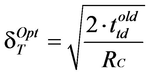 (3)
(3)
During the retransmission of the cells stored already in the buffer, the new ones, coming from the fixed segment of the connection have to be queued first, in order to be sent segmentwise afterwards on the new mobile path. The buffer can be emptied only if the reading rate is higher than the average cell rate of the connection RGB > RC. In this case, the time interval in which the content of
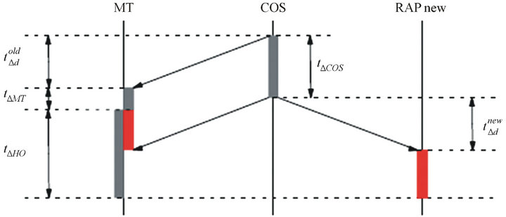
Figure 5. Buffer arrangement for 8TH.
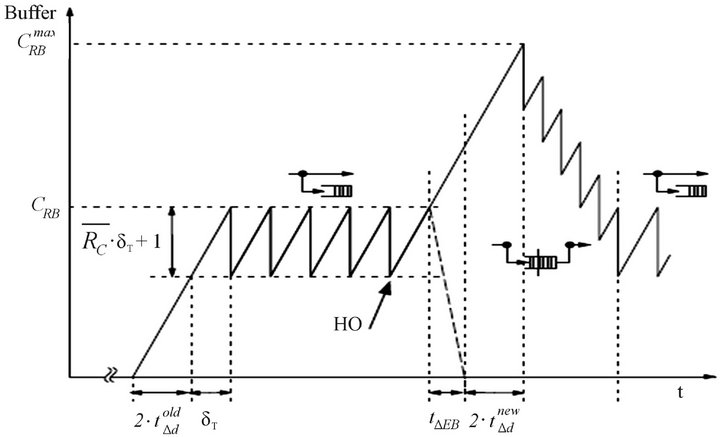
Figure 6. Downlink propagation delays for the backward HO.
the buffer is retransmitted is:
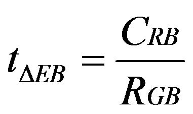 (4)
(4)
As stated before, the new cells fill up the buffer, during retransmission, with the rate RC, until the tags can be again received in uplink direction. Figure 6 presented the worst case in which the MT performs the physical handover shortly after the reception of the last tag in uplink direction, with the result, that all the cells forwarded from the buffer did not yet reach the MT. They are now retransmitted with the increased rate RGB > RC; towards MT and segmentwise confirmed. The buffer is emptied step by step and the system regains a normal, stable state. The maximum fill-up level of the buffer can be calculated out of the formula below:
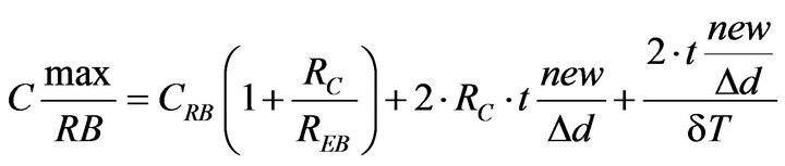 (5)
(5)
6. OAM Implementation of the STH Scheme
Obviously, the proposed algorithm relies on the standard ATM OAM functionality [6,14]. Basically, the in-band signaling mechanism used in order to protect data corresponds directly to the OAM principle, in which connection specific management and operations information are transmitted inside the user-data stream. The delay measurement mechanism used in the STH method for dynamically adapting the retransmission buffer size is an adaptation of the VCC OAM cell loopback. The loopback capability of the ATM-OAM enables the dynamic insertion of both the intermediated connection points and endpoints and to be transmitted back by a third, remote point.
This remote point is in the case of STH the MT, which sends back on the mobile segment the information generated by the COS. A separate counter is used to determine the number of user data cells received on the corresponding VC after the last received numbering tag. This information is then used to resynchronize the data stream after the handover. After the reception of a certain numbering tag sent back by the endpoint, the COS discards the content of the buffer belonging to the corresponding connection, in other words, the cells stored in it prior to the transmission of the SAI signal. This assures that the buffer contains only copies of user data cells either not yet received or not yet acknowledged by the MT. The SAI process is continuous, in a loop, and is reinitialized after every successful handover attempt. Its main purpose is the management and the content-refresh of the STH retransmission buffer. After the validation of a handover attempt and the establishment of the connection between the COS and the new RAP, the buffer content is transmitted to the new RAP.
Once the MT received the permission for handover, it has to finish the transmission of user data cells on the old connection, this being done with the help of the MDI signal. This OAM cell marks the last user data cell transmitted in the uplink direction via the old RAP. Upon receiving the MDI cell, the COS ceases transmitting on the old downlink and updates its routing tables to switch over the connection to the new route via the new RAP and connect the connection's fixed segment to the new mobile segment. After that, the old mobile segment is shut down. The user data cells contained in the retransmission buffer are sent to the new RAP followed by the normal cell stream received from the fixed segment. Handover completion is signaled by a HCI OAM cell which has also the role of triggering the queuing of user data cells following this signal, until the post handover resynchronization is initialized by the MT at the new RAP. The buffer in the new RAP is activated upon receipt of HCI and starts storing cells. The MT itself starts the transmission on the new link, after completing the physical part of the handover, by sending also a HCI signal containing the numbering tag of the last SAI correctly received on the old downlink together with the value of the synchronization counter. In a similar way, the RAP discards the appropriate number of cells from the buffer and starts regular transmission in both upand downlink direction. A final HCI signal sent on the uplink by the MT is flagging successful handover completion to the COS. The described mechanism protects connections with high requirements regarding QoS from cell loss or cell sequence mismatch. The signaling flow used by the STH handover scheme is similar to the OAM F5 flow. In addition to the described handover procedure, new signaling functions are needed for proper handover triggering and setup or shutdown of the mobile segment.
Due to the very small cell size, handover are occurring more and more frequently and they should be seen as a normal process of continuous improvement of the radio link rather than an emergency situation. The aim of every handover scheme should be therefore to reduce the impact to the connection in terms of QoS to a minimum. To achieve this goal, the OAM functionality for handover should be in charge of in-time recognition of a handover situation and fast switching of the active connections to the new access point RAP, if possible before radio link failure. This is different than standard ATM fault situations, where a certain delay responding to alarm indications is provided in the ATM layer waiting for lower layer protection mechanism to be activated and at the same time a short disruption of service in the order of several hundred milliseconds is regarded as acceptable due to the singular nature of ATM VPCIVCC faults.
Therefore, the standard OAM fault management is not suited to handle handover situations, a distinct handover management being necessary. The implementation of this can still be realized together with the ATM OAM functions because, as seen before, the special requirements are mainly in the field of the performance of the handover OAM functions.
In the particular case of STH handover, an OAM cell stream per mobile VCC is required, meaning that the handover management cells are belonging to an F5 type of OAM flows.
This in-band signaling handover management stream is at the same time a segment oriented stream, having the endpoints at the mobile terminal MT, access point RAP and respectively, cos. The OAM signals are shown in Table l and the message flow for the acknowledgement of received numbering information and the synchronization process during handover is displayed in Figure 7.
The signal having the most frequent occurrence is SAI, due to the fact that it is transporting a numbering label in order to exchange synchronization points in the user data stream between COS and MT. The SAI cells are the one that are inserted periodically into the user data stream of a VC by the COS. Those cells contain the sequentially numbered tag defined in the STH handover scheme. The user data cells arriving after SAI are copied by the OAM module to the STH retransmission buffer. The SAI cells have to be returned to the COS by the endpoint of the mobile segment of the VC which is the mobile terminal MT. When receiving an SAI signal, MT would reset the synchronization counter, save the numbering tag received
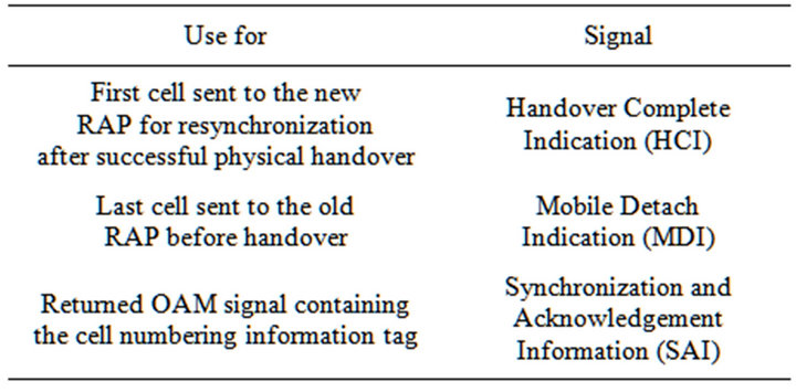
Table 1. OAM signals for STH handover management.
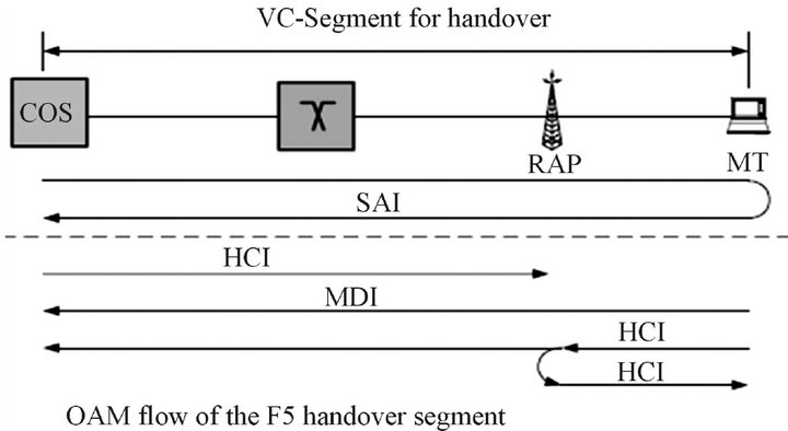
Figure 7. GAM signals of the STH method.
with the SAI signal and send back the SAI cell to the originating point.
7. Conclusion
Based on a mobile ATM reference architecture, consisting of a wireless access system paired with the support of mobile end-systems within the ATM network, and after detailing the handover functions related to it, a new handover procedure called Sync Tag Handover STH is being proposed and discussed in this paper. To justify the need of a lossless handover scheme, the potential error scenarios are presented and also the way in which the new procedure overcomes them. The tag insertion mechanism is explained in detail together with the administration of the buffer storing copies of the ATM cells sent in downlink direction on the mobile segment. Finally, the OAM implementation of the procedure is presented, underlying the advantages of this scheme in terms of maintaining QoS and easy implementation in existing ATM OAM.
REFERENCES
- L. Dellaverson, “Reaching for the New Frontier,” 53 Bytes—The ATM Forum Newsletter, Vol. 4, No. 3, 1996.
- ATM-Forum, “ATM User-Network Interface Specification,” Version 4.1, 2002.
- B. A. Akyol and D. C. Cox, “Rerouting for Handoff in a Wireless ATM Network,” IEEE Personal Communications Magazine, Vol. 3, No. 5, 1996, pp. 26-33. doi:10.1109/98.542235
- A. S. Acampora and M. Naghshineh, “Control and Quality-of Service Provisioning in High-Speed Microcellular Networks,” IEEE Personal Communications Magazine, Vol. 1, No. 2, 1994.
- ATM-Forum, “Domain-Based Rerouting for Active PointTo-Point-Calls,” Version 1.0, 2001.
- T. S. Chen and S. S. Liu, “Management and Control Functions in ATM Switching Systems,” IEEE Network, Vol. 8, No. 4, 1994, pp. 27-40. doi:10.1109/65.298161
- A. Acharya, B. Rajagopalan and D. Raychaudhuri, “Mobility Management in Wireless ATM Networks,” IEEE Communications Magazine, Vol. 35, No. 11, 1997, pp. 100-109. doi:10.1109/35.634767
- B. Edmaier, W. Fischer, J. Eberspacher and A. Klug, “Alignment Server for Hitless Path Switching in ATM Networks,” Proceedings of the International Switching Symposium ISS, Vol. 2, Berlin, 23-28. April 1995, pp. 403-407.
- B. Edmaier, “Pfad-Ersatzschalte-Verfahren mit Verteilter Steuerung fur ATM-Netze,” Ph.D. Thesis, Technische Universitat Munchen, München, 1996.
- H.-J. Vogel, “Handover Switching in Mobile ATM Networks,” Conference Proceedings EPMCC’97, Bonn, 30 September 1997, pp. 375-381.
- H. Mitts, H. Hansen, J. Irnrnonen and S. Veikkolainen, “Lossless Handover for Wireless ATM,” Mobile Networks and Applications, Vol. 1, No. 3, 1996, pp. 299-312. doi:10.1007/BF01193263
- H.-J. Vogel, “Robust and Soft: Handover Design for High-Tier Mobile ATM Systems,” Conference Proceedings of Wireless’99, Munich, 6-8 October 1999, pp. 333- 338.
- B. Walke, D. Petras and D. Plassmann, “Wireless ATM: Air Interface and Network Protocols of the Mobile Broadband System,” IEEE Personal Communications Magazine, Vol. 3, No. 4, 1996, pp. 50-56.
- D. Minoli, and T. Golway, “Planning & Managing ATM Networks,” Manning, Greenwich, 1996.