Journal of Signal and Information Processing
Vol.06 No.02(2015), Article ID:55945,12 pages
10.4236/jsip.2015.62012
Huffman Image Compression Incorporating DPCM and DWT
Mohamed Abo-Zahhad1, Reda Ragab Gharieb1, Sabah M. Ahmed1, Mahmoud Khaled Abd-Ellah2
1Department of Electrical and Electronics Engineering, Faculty of Engineering, Assiut University, Assiut, Egypt
2Department of Electronics and Communication Engineering, Madina Higher Institute for Engineering and Technology, Giza, Egypt
Email: Eng_mahmoudkhaled@yahoo.com
Copyright © 2015 by authors and Scientific Research Publishing Inc.
This work is licensed under the Creative Commons Attribution International License (CC BY).
http://creativecommons.org/licenses/by/4.0/


Received 5 March 2015; accepted 22 April 2015; published 24 April 2015
ABSTRACT
This paper presents a medical image compression approach. In this approach, first the image is pre-processed by Differential Pulse Code Modulator (DPCM), second, the output of the DPCM is wavelet transformed, and finally the Huffman encoding is applied to the resulting coefficients. Therefore, this approach provides theoretically threefold compression. Simulation results are presented to compare the performance of the proposed (DPCM-DWT-Huffman) approach with the performances of the Huffman incorporating DPCM (DPCM-Huffman), the DWT-Huffman and the Huffman encoding alone. Several quantitative indexes are computed to measure the performance of the four algorisms. The results show that the DPCM-DWT-Huffman, the DWT-Huffman, the DPCM- Huffman and the Huffman algorisms provide compression ratio (CR) of 6.4837, 4.32, 2.2751 and 1.235, respectively. The results also confirm that while the proposed DPCM-DWT-Huffman approach enhances the CR, it does not deteriorate other performance quantitative measures in comparison with the DWT-Huffman, the DPCM-Huffman and the Huffman algorisms.
Keywords:
Medical Image Compression, Brain Image Compression, CT, DPCM, DWT, CR

1. Introduction
The main objective of image compression techniques is to reduce the image size for less storage and transmission bandwidth by discarding irrelevance and redundancy of the image data. These techniques can be classified into two categories: lossless and lossy compression techniques. Lossless techniques are applied when data are critical and loss of information is not acceptable. Hence, many medical images should be compressed by lossless techniques [1] . Medical image processing and compression have become important to medical field. Nowadays, many hospitals around the world use compression to store routinely-made patient images for follow-up and tracking the patient state. There have been many studies on medical image lossless compression [2] - [6] . Several image compression techniques encode transformed image data instead of the original images [7] - [11] . This has been motivated by adding primary compression or size reduction, due to transformation, before final encoding. Differential pulse code modulation (DPCM) has been used to add data compression prior to Huffman encoding. In this approach, compression can be theoretically twofold. This DPCM-Huffman compression has been applied to medical images [12] .
An efficient compression method for medical images is proposed. The method is based on adding a data size reduction to the DPCM output prior to Huffman encoding. This is done by discreet wavelet transformation (DWT). The DWT is an efficient method to represent data with fewer numbers of coefficients. Then, the expected compression can be threefold. Comparison between the proposed method and other ones to measure the performance has been applied. Other methods have been explained in details in next section. The paper is organized as follows. In Section 2, the main idea of Huffman encoding is presented. The DPCM-Huffman method is discussed in Section 3. In Section 4, The DWT-Huffman is discussed. In Section 5, the proposed method of incorporating the DWT with the DPCM-Huffman compression method is discussed. Section 6 shows and discusses the compression results provided by the four techniques: Huffman, DPCM-Huffman, DWT-Huffman and the proposed DPCM-DWT-Huffman. Finally, Section 7 presents the conclusion.
2. Huffman
Figure 1 shows a schematic block diagram for image compression using Huffman encoding method. The Huffman encoding starts with calculating the probability of each symbol in the image. The symbols probabilities are arranged in a descending order forming leaf nodes of a tree. When the symbols are coded individually, the Huffman code is designed by merging the lowest probable symbols and this process is repeated until only two probabilities of two compound symbols are left. Thus, a code tree is generated and Huffman codes are obtained from labelling of the code tree. The minimal length binary code for a two-symbol source, of course, is the symbols 0 and 1. The Huffman codes for the symbols are obtained by reading the branch digits sequentially from the root node to the respective terminal node or leaf. Huffman coding is the most popular technique for removing coding redundancy as shown in Figure 2 [13] . Huffman code procedure is based on the following two observations.
1) More frequently occurred symbols will have shorter code words than symbol that occur less frequently;
2) The two symbols that occur least frequently will have the same length.
The average length of the code is given by the average of the product of probability of the symbol and number of bits used to encode it. More information can found in [14] [15] .
And the Huffman code efficiency is calculated as
 (1)
(1)
Huffman’s procedure creates the optimal code for a set of symbols and probabilities subject to the constraint that the symbols be coded one at a time [13] .
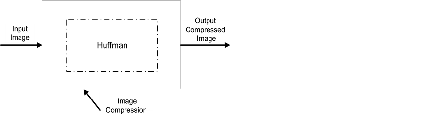
Figure 1. Schematic diagram of image compression using Huffman encoding.

Figure 2. Huffman coding procedure [4] .
The entropy (H) of the source can be determined from the following Equation (2). The entropy value describes how much compression is possible for that image in the form of bit per pixel. It should be noted that, there cannot be any possible compression ratio smaller than entropy. The entropy of any image is calculated as the average information probability. Entropy indicates the required amount of bits per pixel [12] .
 (2)
(2)
where pk is the probability of intensities, k is the intensity value, and L is the number of intensity values used to present image.
3. DPCM-Huffman
In [12] , a modification of Huffman method has been developed based on DPCM predictor for hardware implementation of lossless medical brain CT image compression. DPCM-Huffman method improves the conventional Huffman method by transforming the input image with DPCM and the transformed data is inputted to the conventional Huffman encoding. The DPCM has been carried out by studying all possible predictors and select the most efficiency one through the calculation of the entropy of each predictor and comparing between them. Therefore a twofold of compression could be obtained. Figure 3 illustrates a schematic diagram for the DPCM- Huffman algorithm.
Differential pulse code modulation (DPCM) is an operation of converting a signal into a predicted one. Then the differences between the original signal values and predicted ones are encoded and stored. DPCM compression method can be conducted for intra and inter frame coding. Intra coding exploits spatial redundancy and inter coding exploits temporal redundancy. In the intra-frame coding, is formed by the difference between the neighbouring pixels of the same frame, further, the inter-frame is formed between two consecutive frames for the same value. In both the value of target pixel is predicted by neighbouring pixels. DPCM compression depends on the prediction technique, which leads to good compression rates [16] .
DPCM prediction is nonlinear. Its basic idea is to predict the value in every image pixel and make the predicted error entropy less than the original image entropy. Because there is strong correlation among adjacent pixels, current pixel values are predicted by knowledge of its adjacent pixels.
Figure 4 shows illustrative example where the predicted value of , is computed based on given values of neighbour pixels A, B, C and D. The predicted error
  is saved in the position of X. However, when it comes to the image boundary, one or two values among A, B, C and D do not exist For the first pixel in the upper left corner, all of the three values do not exist. Thus, this pixel is not predicted and its value is saved in the header information of the output code stream [17] .
4. DWT-Huffman
Figure 5 shows The Discrete Wavelet Transform (DWT) of a sequence consists of two series expansions, one corresponding to the approximation and the other to the details of the sequence. The formal definition of DWT

Figure 3. Schematic diagram of the image compression algorithm using DPCM-Huffman encoding.

Figure 4. Prediction model of DPCM system.
of an N-point sequence x [n], 0 ≤ n ≤ N − 1 is given by
 (3)
(3)
where,  and
and . It is more efficient to implement the 2D DWT using 1D DWT. This arises from the following two issues.
1) A lot of 1D wavelet design materials exist in the literature;
2) Fast implementation of 1D DWT is also available.
Here, the 2D discrete wavelet transform has been adopted for image compression. We will, therefore, focus our attention on the implementation of 2D DWT of an image using 1D DWT in a row-column fashion [18] . We first filter it row by row by the filter  and
and  as shown in Figure 5(a), and retain every other sample at the filter outputs. This gives a set of two DWT coefficients each of size N × N/2. Next, the DWT coefficients of the filter
  are filtered again along each column by the same two filters and subsampled by 2 to yield two other sets of DWT coefficients of each size N/2 × N/2. Finally, the DWT coefficients due to
  are filtered along the columns by the same two filters and subsampled to give two other sets of DWT coefficients of each size N/2 × N/2. The LL coefficients correspond to lowpass in the horizontal direction and lowpass in the vertical direction.
The HL coefficients correspond to highpass in the horizontal direction and lowpass in the vertical direction. Thus, the HL coefficients follow horizontal edges more than vertical edges. The LH coefficients follow vertical edges because they correspond to highpass in the vertical direction and low-pass in the horizontal direction. Finally, the HH coefficients preserve diagonal edges.
Figure 5(b) show the LL, HL, LH, and HH when one level wavelet is applied to Lena image. It is obvious that the LL output preserve all information about the image while the size is quarter of original image size this implies that one level wavelet can provide compression ratio of four. If we ignore the HL, LH, and HH, to reconstruct back the original image from the LL (cA), HL (cD(h)), LH (cD(v)), and HH (cD(d)) coefficients, the inverse 2D DWT is applied as shown in Figure 6 [19] .
Figure 7 shows other modification of Huffman method has been developed based on wavelet transform for lossless medical CT images compression. DWT-Huffman method improves the conventional Huffman method by transforming the input image with DWT and the transformed data is inputted to the conventional Huffman encoding. The wavelet transform is applied to input image to obtain the approximation and detailed coefficients

 (a) (b)
Figure 5. Filtering implementation of 2D-DWT [21] .

Figure 6. One level inverse 2D-DWT [20] .

Figure 7. Schematic diagram for the image compression algorithm using DWT- Huffman encoding.
representing the error signal. Then the Huffman encoding is applied to the nonzero coefficients. The wavelet family Haar of level one has been used.
5. DPCM-DWT-Huffman
To gain more compression we propose to incorporate the DWT within the DPCM-Huffman algorithm explained in Section 5 as shown in Figure 8 which provides lossless compression method. Thus the compression ratio (CR) can be threefold of the Huffman algorithm. Wavelet analysis has been known as an efficient approach to repre-

Figure 8. Schematic diagram for the image compression algo- rithm using DPCM-DWT-Huffman encoding.
senting data (signal or image) by approximation and detailed coefficients. In one level image analysis, the approximation wavelet coefficient shows the general direction of the pixel value, and three detailed coefficients shows vertical, horizontal and diagonal details. Compression ratio increases when the number of wavelet coefficients that are equal zeroes increases [21] . Fortunately, in practice, it has been found that many images can be represented by fewer number of wavelet coefficients. Therefore, our proposed method is to take advantage of wavelet transform.
The DPCM has been carried out by studying all possible predictors and select the most efficiency one through the calculation of the entropy of each predictor and comparing between them, which found B is the best predictor. However, the prediction error (e), which is the difference between the actual value of the current pixel (X) and the predicted one (B) is given by the following equation.
 (4)
(4)
Proposed method applies the wavelet transform to the prediction error generated by DPCM to obtain the approximation and detailed coefficients representing the error signal. Then, the Huffman encoding is applied to the nonzero coefficients and to reject other ones. Figure 5 shows a schematic diagram for one level wavelet transform. Therefore, the compression ratio can vary from wavelet type to another depending which one can repre- sented the DPCM error signal in fewer number coefficients.
6. Results and Discussion
6.1. Performance Measures
The most common objective performance measures used are Maximum Absolute Error (MAE), Mean Square Error (MSE), Root Mean Square Error (RMSE), Signal-to-Noise Ratio (SNR), Peak Signal-to-Noise Ratio (PSNR), Compression Ratio (CR). The error function between the reconstructed and original images is given by
 (5)
(5)
where  is the original image and
  is the reconstructed image generated form the compressed image data. The MAE is given by
 (6)
(6)
The MSE is the second moment of the error function between the reconstructed and original images, given by [22] .
 (7)
(7)
where, M × N is the image size. The RMSE is simply the square root of the MSE given by (3).
The SNR in dB is given by
 (8)
(8)
where the numerator is the power of the original image and denominator is the additive noise corrupting the reconstructed image. The PSNR measure the ratio the maximum pixel intensity  (where B is number of bits) to MSE given by [22] .
 (9)
(9)
Therefore, a higher value of PSNR offers better performance. The CR is often computed by dividing the size of the original image in bits over the size of the compressed image data. Thus it is given by [23] .
 (10)
(10)
The three methods, Huffman, DPCM-Huffman and the proposed DPCM-DWT-Huffman, have been applied to three CT medical images with different sizes.
6.2. Simulation Result
To show the rational of incorporating the wavelet transform between the DPCM and Huffman coding, we have executed the following simulation. For an exemplary image shown in Figure 9(a), we have computed the histogram of an exemplary image, Figure 9(b), histogram of wavelet transform (approximation and details coefficient) as shown in Figure 9(c) and Figure 9(d) respectively. We have computed the DPCM of the image shown in Figure 9(e), its histogram, shown in Figure 9(f), and the histogram of wavelet transform (approximation and details coefficient) of DPCM image shown in Figure 9(g) and Figure 9(h) respectively. It is apparent that the wavelet transform after the DPCM provides denser histogram than the histogram of wavelet transform directly of the image. This dense in the distribution leads to small number of Huffman coding. In this example, the Huffman coding of the approximation coefficient associated with the wavelet transform of the image provides 312 codes (final coded size = 121,325 bit), while on the approximation coefficient associated with the DPCM image provides 119 code in the codebook (final coded size = 80,863 bit). The Haar wavelet of level one has been used in this example. It is worthwhile to mention that while the Huffman codding of DPCM image provides 46 code number the data to be coded is full size of the image (final coded size = 230,443 bit).
 (a) (b) (c) (d)
 (e) (f) (g) (h)
Figure 9. (a) Original image; (b) original image histogram; (c) DWT of original image (approximation coeffeicint) histo- gram; (d) DWT of original image (details coeffeicint) histrogram; (e) DPCM output; (f) DPCM output histogram; (g) DWT of DPCM output (approximation coeffeicint) histogram; (h) DWT of DPCM output (details coeffeicint) histogram.
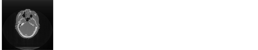
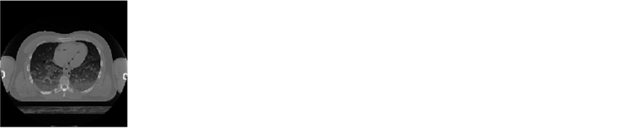
We have also applied the proposed DPCM-DWT-Huffman on different medical images shown in Figures 10-12 which selected from U.S. National Library of Medicine (NLM) [24] . Image is Specimen from human male. A fresh CT image for head and Thorax with Portable Network Graphics (.png) format, Bitmap Image, which have 256 × 256 for first one and 512 × 512 for second and third one with 8-bit depth each pixel, which have gray scale value from 0 to 255 which indicate the component of image with size 60KB for first image, 59KB for second one and 77 KB for third one. Tables 1-3 provide the performance measures of the DPCM- DWT-Huffman in comparison with Huffman and DPCM-Huffman methods. Different wavelet types and different level have been tested. The results have shown that the CR of DPCM-DWT-Huffman, DWT-Huffman, DPCM-Huffman and Huffman methods are 6.48, 4.32, 2.27 and 1.2 respectively. The other compression performance measures provided by DPCM-DWT-Huffman, DWT-Huffman and DPCM-Huffman are slightly the same.

Table 1. Comparison between our method and other ones.
Table 2. Comparison between our method and other ones.
Table 3. Comparison between our method and other ones.


 (a) (b) (c) (d)


 (e) (f) (g) (h)

 (i) (j) (k) (l)


 (m) (n) (o) (p)


 (q) (r) (s) (t)
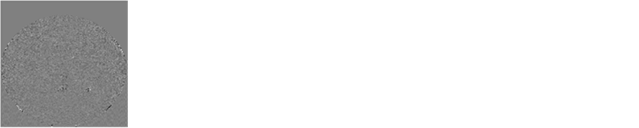
Figure 10. (a) Original image (CT brain); (b) Reconstructed image from Huffman compression; (c) DPCM output from DPCM-Huffman method; (d) Reconstructed image from DPCM-Huffman compression; (e) wavelet approximation coefficient from DWT-Huffman; (f) Wavlet details coeffient from DWT-Huffman; (g) Wavlet details coeffient from DWT-Huffman; (h) Reonstructed image from DWT-Huffman; (i) DPCM output from DPCM-DWT-Huffman; (j) Wavelet approximation coefficient from DPCM-DWT-Huffman (db1); (k) Wavelet details coefficient from DPCM-DWT-Huffman (db1); (l) Reconstructed image from DPCM-DWT-Huffman (db1); (m) DPCM output from DPCM-DWT-Huffman; (n) Wavelet approximation coefficient from DPCM-DWT-Huffman (db4); (o) Wavelet details coefficient from DPCM-DWT-Huffman (db4); (p) Reconstructed image from DPCM-DWT-Huffman (db4); (q) DPCM output from DPCM-DWT- Huffman; (r) Wavelet approximation coefficient from DPCM-DWT-Huffman (haar); (s) Wavelet details coefficient from DPCM-DWT-Huffman (haar); (t) Reconstructed image from DPCM-DWT-Huffman (haar).


 (a) (b) (c) (d)


 (e) (f) (g) (h)


 (i) (j) (k) (l)


 (m) (n) (o) (p)


 (q) (r) (s) (t)
Figure 11. (a) Original image (CT brain); (b) Reconstructed image from Huffman compression; (c) DPCM output from DPCM-Huffman method; (d) Reconstructed image from DPCM-Huffman compression; (e) Wavelet approximation coefficient from DWT-Huffman; (f) Wavlet details coeffient from DWT-Huffman; (g) Wavlet details coeffient from DWT-Huffman; (h) Reonstructed image from DWT-Huffman; (i) DPCM output from DPCM-DWT-Huffman; (j) Wavelet approximation coefficient from DPCM-DWT-Huffman (db1); (k) Wavelet details coefficient from DPCM-DWT-Huffman (db1); (l) Reconstructed image from DPCM-DWT-Huffman (db1); (m) DPCM output from DPCM-DWT-Huffman; (n) Wavelet approximation coefficient from DPCM-DWT-Huffman (db4); (o) Wavelet details coefficient from DPCM-DWT-Huffman (db4); (p) Reconstructed image from DPCM-DWT-Huffman (db4); (q) DPCM output from DPCM-DWT- Huffman; (r) Wavelet approximation coefficient from DPCM-DWT-Huffman (haar); (s) Wavelet details co- efficient from DPCM-DWT-Huffman (haar); (t) Reconstructed image from DPCM-DWT-Huffman (haar).


 (a) (b) (c) (d)


 (e) (f) (g) (h)


 (i) (j) (k) (l)

 (m) (n) (o) (p)


 (q) (r) (s) (t)
Figure 12. (a) Original image (CT thorax); (b) Reconstructed image from Huffman compression; (c) DPCM output from DPCM-Huffman method; (d) Reconstructed image from DPCM-Huffman compression; (e) Wavelet approximation coefficient from DWT-Huffman; (f) Wavlet details coeffient from DWT-Huffman; (g) Wavlet details coeffient from DWT-Huffman; (h) Reonstructed image from DWT-Huffman; (i) DPCM output from DPCM-DWT-Huffman; (j) Wavelet approximation coefficient from DPCM-DWT-Huffman (db1); (k) Wavelet details coefficient from DPCM-DWT-Huffman (db1); (l) Reconstructed image from DPCM-DWT-Huffman (db1); (m) DPCM output from DPCM-DWT-Huffman; (n) Wavelet approximation coefficient from DPCM-DWT-Huffman (db4); (o) Wavelet details coefficient from DPCM-DWT-Huffman (db4); (p) Reconstructed image from DPCM-DWT-Huffman (db4); (q) DPCM output from DPCM-DWT- Huffman; (r) Wavelet approximation coefficient from DPCM-DWT-Huffman (haar); (s) Wavelet details co- efficient from DPCM-DWT-Huffman (haar); (t) Reconstructed image from DPCM-DWT-Huffman (haar).
7. Conclusion
In this paper, we have presented a new image compression technique consisting of the association of the DPCM, the DWT and the Huffman coding. In this technique, first the image is passed through the DPCM transformation, second the wavelet transformation is applied to the DPCM output, and finally the wavelet coefficients are encoded by the Huffman coding. So, the wavelet transformation reduces the redundancy and spatial reputation in the image data, which makes the compression more efficiently. Simulation results have shown that the proposed DPCM-DWT-Huffman outperforms the DWT-Huffman, DPCM-Huffman and Huffman methods. The four methods provide CR of 6.48, 4.32, 2.27 and 1.2 respectively.
References
- Masood, S., Sharif, M., Yasmin, M., Raza, M. and Mohsin, S. (2013) Brain Image Compression: A Brief Survey. Engineering and Technology, 5, 49-59.
- Shaou-Gang, M., Fu-Sheng, K. and Shu-Ching, C. (2009) A Lossless Compression Method for Medical Image Sequences Using JPEG-L Sand Interframe Coding. IEEE Transactions on Information Technology in Biomedicine, 13, 818-821.
- Tzong-Jer, C. and Keh-Shih, C. (2010) A Pseudo Lossless Image Compression Method. Image and Signal Processing (CISP). 3rd International Congress, 2, 610-615.
- Dubey, V.G. and Singh, J. (2012) 3D Medical Image Compression Using Huffman Encoding Technique. ECE Department, RIEIT Railmajra, SBS Nagar, Punjab, International Journal of Scientific and Research Publications, Vol. 2, Issue 9.
- Anju, B. and Manimurugan, S. (2012) An Approach to Medical Image Compression Using Filters Based on Lifting Scheme. IOSR Journal of VLSI and Signal Processing, 1, 9-16. http://dx.doi.org/10.9790/4200-0120916
- Kumar, S., Goel, N., Singh, V., Chaudhary, A., Sirohi, N. and Singh, G. (2013) Fast and Efficient Medical Image Compression Using Contourlet Transform: (FEMI-CCT). Ganpati Institute of Technology & Management, India, Open Journal of Computer Sciences, 1, 7-13.
- Hu, L.L., Zhang, F., Wang, Z., You, X.F., Nie, L., Wang, H.X., Song, T. and Yang, W.H. (2010) Comparison of the 1HR Relaxation Enhancement Produced by Bacterial Magnetosomes and Synthetic Iron Oxide Nanoparticles for Potential Use as MR Molecular Probes. IEEE Transactions on Applied Superconductivity, 20, 822-825.
- Corvetto, A., Ruedin, A. and Acevedo, D. (2010) Robust Detection and Lossless Compression of the Foreground in Magnetic Resonance Images. Data Compression Conference (DCC), Snowbird, 24-26 March 2010, 529. http://dx.doi.org/10.1109/DCC.2010.74
- Soundarya, G. and Bhavani, S. (2012) Comparison of Hybrid Codes for MRI Brain Image Compression. Maxwell Scientific Organization, 15 December 2012.
- Alagendran, B., Manimurugan, S. and John Justin, M. (2012) Compression of 3D Medical Image Using EDGE Preservation Technique. International Journal of Electronics and Computer Science Engineering, 1, 802-809.
- Ghrare, S.E. and Shreef, S.M. (2012) Proposed Quality Evaluation of Compressed MRI Medical Images for Telemedicine Applications. World Academy of Science, Engineering and Technology, 6, 568-570.
- Sepehrband, F., Mortazavi, M. and Ghorshi, S. (2010) Efficient DPCM Predictor for Hardware Implementation of Lossless Medical Brain CT Image Compression. International Conference on Signals and Electronic Systems (ICSES), Gliwice, 7-10 September 2010, 123-126.
- Pujar, J.H. and Kadlaskar, L.M. (2010) A New Lossless Method of Image Compression and Decompression using Huffman Coding Techniques. Journal of Theoretical and Applied Information Technology, 15, 18-23.
- Gupta, K., Verma, R.L. and Sanawer Alam, Md. (2013) Lossless Medical Image Compression Using Predictive Coding and Integer Wavele Transform based on Minimum Entropy Criteriat. International Journal of Application or Innovation in Engineering & Management (IJAIEM), 2, 98-106.
- Mishra, K., Verma, R.L., Alam, S. and Vikram, H. (2013) Hybrid Image Compression Technique using Huffman Coding Algorithm. International Journal of Research in Electronics & Communication Technology, 1, 37-45.
- Wurde Kopiert Von http://einstein.informatik.uni-oldenburg.de/rechnernetze/dpcm.htm
- Zhao, L., Tian, Y., Sha, Y. and Li, J. (2009) Medical Image Lossless Compression Based on Combining an Integer Wavelet Transform with DPCM. Frontiers of Electrical and Electronic Engineering in China, 4, 1-4. http://dx.doi.org/10.1007/s11460-009-0014-1
- Abo-Zahhad, M., Gharieb, R.R., Ahmed, S.M. and Khaled, M. (2015) Brain Image Compression Techniques. International Journal of Engineering Trends and Technology (IJETT), 19, 93-105.
- Thyagarajan, K.S. (2011) Still Image and Video Compression with Matlab. John Wiley & Sons, Inc., Hoboken.
- MathWorks http://www.mathworks.com/help/wavelet/ref/idwt2.html
- Bansal, N. and Dubey, S.K. (2013) Image Compression Using Hybrid Transform Technique. Journal of Global Research in Computer Science, 4, 13-17.
- Er. Ramandeep Kaur Grewal and Randhawa, N. (2012) Image Compression Using Discrete Cosine Transform & Discrete Wavelet Transform. Proceedings of “I-Society 2012” at GKU, Talwandi Sabo Bathinda (Punjab). http://www.researchmanuscripts.com/index.php?option=com_content&view=article&id=67&Itemid=76
- Telagarapu, P., Naveen, V.J., Prasanthi, A.L. and Santhi, G.V. (2011) Image Compression Using DCT and Wavelet Transformations. International Journal of Signal Processing, Image Processing and Pattern Recognition, 4, 61-70.
- U.S. National Library of Medicine (NLM) http://www.nlm.nih.gov/research/visible/fresh_ct.html