International Journal of Medical Physics, Clinical Engineering and Radiation Oncology
Vol.3 No.1(2014), Article ID:43054,7 pages DOI:10.4236/ijmpcero.2014.31008
Medical Image Registration Using the Fourier Transform
Department of Radiation Oncology, Loyola University Medical Center, Maywood, USA
Email: jroeske@lumc.edu
Copyright © 2014 Jason Luce et al. This is an open access article distributed under the Creative Commons Attribution License, which permits unrestricted use, distribution, and reproduction in any medium, provided the original work is properly cited. In accordance of the Creative Commons Attribution License all Copyrights © 2014 are reserved for SCIRP and the owner of the intellectual property Jason Luce et al. All Copyright © 2014 are guarded by law and by SCIRP as a guardian.
Received December 28, 2013; revised January 10, 2014; accepted February 5, 2014
KEYWORDS
Image Registration; Fourier Transform; Pattern Matching
ABSTRACT
A Fourier Transform (FT) based pattern-matching algorithm was adapted for use in medical image registration. This algorithm obtained the FT of two images, determined the normalized cross-power spectrum of the transformed images, and then applied an inverse FT. The result was a delta function with a maximum value at the location corresponding to the distance between the two images; a similar method was used to recover rotations. This algorithm was first tested using a simple two-dimensional image, with induced shifts of ±20 pixels and ±10 degrees. All translations were recovered with no error and all rotations were recovered within 0.18 degrees. Subsequently, this algorithm was tested on eight clinical kV images drawn from four different body sites. Twenty-five random shifts and rotations were applied to each image. The average mean error of the registration solution was −0.002 ± 0.077 mm in the x direction, 0.002 ± 0.075 mm in the y direction, and −0.012 ± 0.099 degrees. These initial results suggest that a FT algorithm has a high degree of accuracy when registering clinical kV images.
1. Introduction
With the advent of modern radiotherapy techniques, such as intensity modulated radiation therapy (IMRT) and stereotactic body radiotherapy (SBRT), increased importance is placed on accurate and reproducible positioning of the patient on a daily basis. In order to ensure that the patient is positioned as intended, image guidance is often used in conjunction with these techniques. An important component of image guidance is the ability to register or align images obtained on the treatment unit with those produced at the time of planning, in order to determine the translations and/or rotations to place the patient in the desired position.
Several methods are currently available for image registration. One of the more common techniques involves the manual alignment of treatment and planning images [1,2]. However, manual alignment requires knowledge of patient anatomy and may suffer from inter-observer and intra-observer variability in determining the correct registration parameters. Other, more automated, methods have been developed which attempt to use the information in the entire image, or some selected sub-area, to guide the image registration process. For example, one such method determines the mutual information (MI) between the two images and iteratively determines the location where they show the highest degree of correlation [3,4]. This method has shown good results, with the caveat that the accuracy of the solution is dependant the on correct choice of the threshold used to guide the iterative processes in the algorithm.
Another, more analytical, method for registering two images is through cross-correlation [2,5]. The convolution of two images that have been shifted with respect to each other results in a function that has its peak value at some displacement from the origin. This displacement corresponds to the distance between the shifted images. While this approach has shown good results for images with sufficient similarity [5] the computational time required for the convolution of two large images can be prohibitive.
A method to address this computational limitation is through the use of the Fourier Transform (FT). A notable property of the FT is that a convolution of two images in the spatial domain is the equivalent to the normalized cross-power spectrum [6]. The inverse FT of the crosspower spectrum results in a delta function that has a peak value at the displacement that corresponds to the distance between the shifted images [7]. This result is, as would be expected, similar to the one gained through crosscorrelation in the spatial domain. Taking advantage of this property of the FT can significantly decrease the time needed to perform the cross-correlation of two images.
The purpose of this study is to examine the efficacy of using a FT-based image registration algorithm for the alignment of daily kV images used for image guidance. FT-based image registration algorithms have been successfully utilized in other fields [2,6-9], and to a limited extent within radiotherapy [10]. However, to our knowledge FT algorithms have not been evaluated with kV images routinely used for daily image guidance.
2. Materials and Methods
2.1. Theory
The FT of an integrable function is defined as:
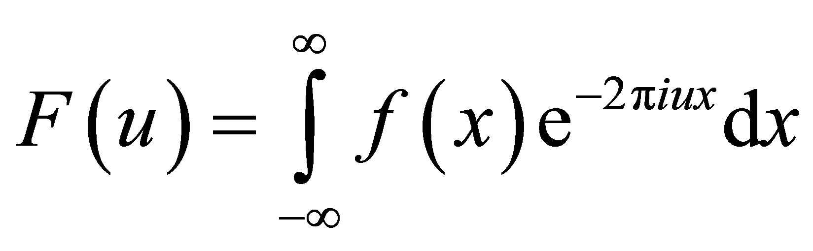 . (1)
. (1)
Historically, one of the more common uses of this transformation is in time dependant signals; if x represents time, then the transformation variable, u, would represent frequency. Since this is one of the more common uses of the FT, the Fourier domain is often referred to as the frequency domain even when dealing with functions that are not time dependent. This transformation is often used in image processing, as any given image can be treated as a two dimensional function where each pixel’s intensity is dependent on its position. However, the discrete nature of images requires the use of the discrete FT. In the context of a two dimensional N × M image, the discrete FT is defined as:
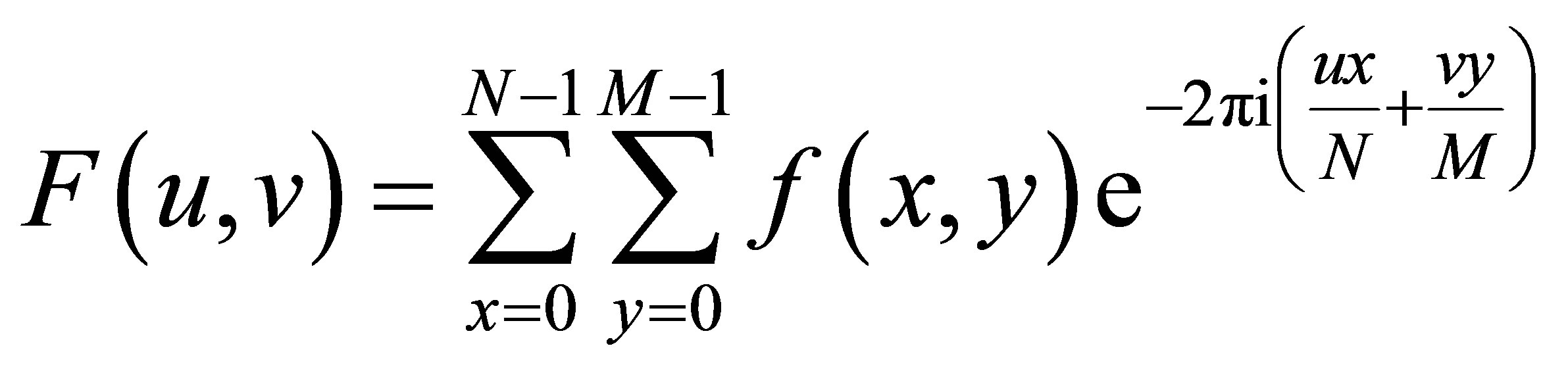 . (2)
. (2)
Throughout the remainder of this paper, FT will be used to refer to the discrete FT as applied to image registration.
To examine the use of the FT within the context of rigid image registration, consider two M × N images where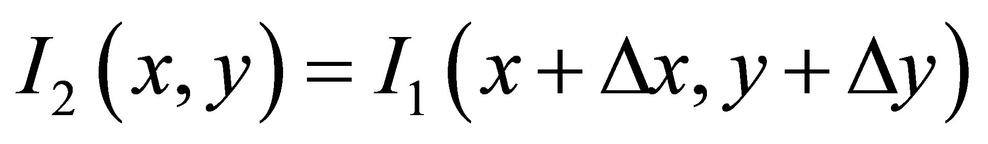 . In other words, I2 is identical to I1 except shifted by Δx pixels in the x direction and Δy pixels in the y direction. The Fourier Shift Theorem states that delaying, or shifting, a signal, f(x) by some distance Δx is the equivalent of multiplying its FT by
 (3)
(3)
This same property applies across multiple dimensions, and the FT of I1 and I2, will be related as follows
 (4)
(4)
where F1 is the FT of I1, and F2 is the FT of I2. The
 (5)
(5)
term can be isolated by calculating the normalized crosspower spectrum:
 (6)
(6)
where  is the complex conjugate of F2. The inverse FT of this complex exponential results in a delta function that has a maximum value at (Δx, Δy) [7] which provides the translational parameters necessary to register I2 to I1.
When there is only a rotational difference, a polar transformation is first applied to the images. This polar transformation is accomplished using
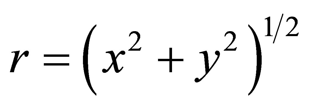 , (7)
, (7)
and
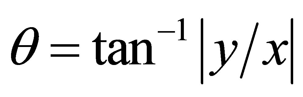 , (8)
, (8)
so that I(x,y) is transformed to I(r,θ). Converting to polar coordinates causes any rotation in an image to become a translation along the axis chosen for θ. Thus, rotations can be recovered using the algorithm described above.
Image registration becomes more complicated if there are both rotational and translational differences between the two images. In this case, simply performing a polar transformation on the images is not enough, as two fundamentally different images will result. Therefore, additional measures are needed in order to register a set of images that are both shifted and rotated with respect to each other.
Two properties of the FT can be used to address this issue. First, it is the nature of the FT that the frequency spectrum is always centered about the origin regardless of any shifts in the underlying image. Second, the rotation of an image will always result in a corresponding rotation in its FT [11].
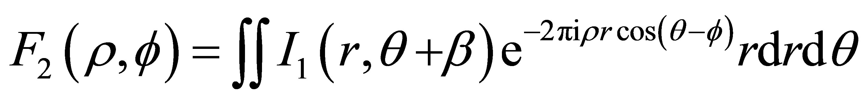
To demonstrate this rotational property, we first transform the images to polar co-ordinates. I(x,y) becomes I(r,θ), and F(u,v) becomes F(ρ,φ), so that
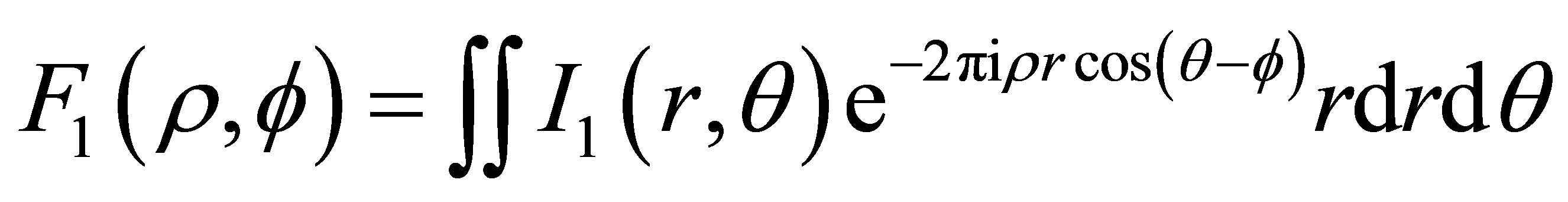 (9)
(9)
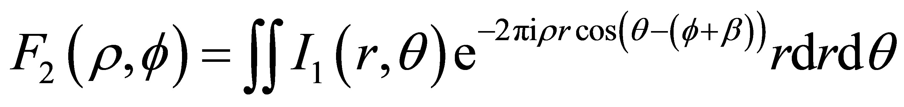
Given an angle β, such that I2 is the rotation of I1 by β in the clockwise direction, it can be seen that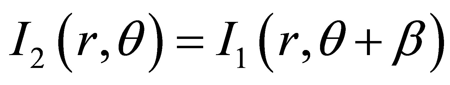 . This means that
 (10)
(10)
which is the equivalent to
 (11)
(11)
so that
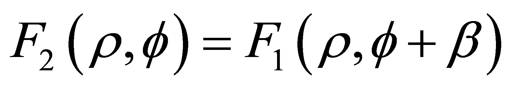 . (12)
These two properties separate the rotational and translational components of image registration so that they can be solved independently. For a set of images that are both shifted and rotated with respect to each other, the rotational shift between the images is isolated by taking their FT. Next, the magnitude of the frequency components created by this FT are treated as if they are the pixel values for a new set of images that only require rotational registration. Once the rotational correction is found it is applied to the underlying image to be registered. Then the translational parameters are found using the same algorithm [7].
While using the FT on a discrete image, two undesirable effects can impact the calculation of its frequency components. One of these is known as aliasing [12,13]; if the intensity of an object changes rapidly over a short distance as compared to the sample rate (i.e. pixel size) of the imager, the frequency component associated with this change may not be captured during the creation of an image. The net result is that high frequency components of an object may be interpreted as lower frequencies in the FT. This effect has little bearing on image registration if the two images were created with the same pixel size. However, problems may occur if the pixel sizes between the images are different, as the frequency decomposition of the two images may have significant differences due to this aliasing effect. The best way to avoid aliasing problems is to use as small a pixel size as is practical in image creation.
The second undesirable effect that can occur during the FT is spectral leakage [14,15]. Images undergoing a FT are treated as if they are periodically extended out to infinity. This property results is a “tiling” effect, and the sharp discontinuities at the edges of the image can generate undesired frequency components in the FT. One way to avoid spectral leakage is to apply a window function to the image so that the pixel values near the edges are damped [14,16]. This will reduce or eliminate any discontinuities at the edges of the image that are caused by the tiling effect. The Hanning (or Hann) window is commonly used for this purpose. For an N × M image, the 2-D Hanning window, H(n,m), is defined as:
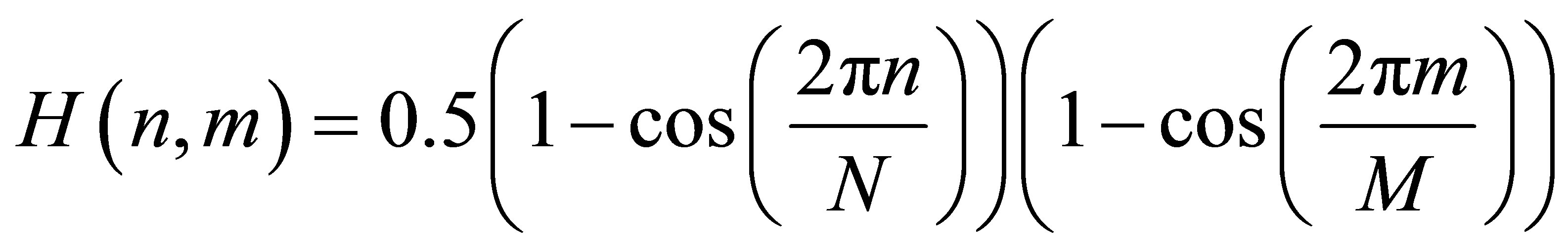 . (13)
2.2. Experimental Methods
The Fast Fourier Transform (FFT), as introduced by Cooley and Tukey [17], is a computationally efficient method for calculating the discrete FT of an image. Based on the theory described above, an FFT registration algorithm was adapted from a program written in Interactive Data Language (IDL; Exelis, Boulder, CO), as described by [7], and characterized for use in radiotherapy. Figure 1 fully illustrates the steps that are performed to register a set of images with both rotational and translational shifts. This algorithm includes the image pre-processing steps that are needed when working with clinical data, as well as the core steps associated with image registration.
As a first step, depending on the intensity distribution in the images being used, a redistribution of the pixel values may be necessary. For the kV images used in this study most of the pixel values were on the very high end of a 16 bit range of grayscale pixel values.
This compact distribution of pixels causes the low frequency components of the FFT to dominate its polar transformation, which inhibits registration. It was found that redistributing the pixel values of the image through histogram equalization allowed for improved rotational registration without having a detrimental effect on the rest of the algorithm.
To minimize the effect of spectral leakage, all the images used in this study had a widened Hanning window applied prior to applying a FFT. The widening of a Hanning window can be accomplished by taking the jth root of the Hanning window as described in (13); for this study,
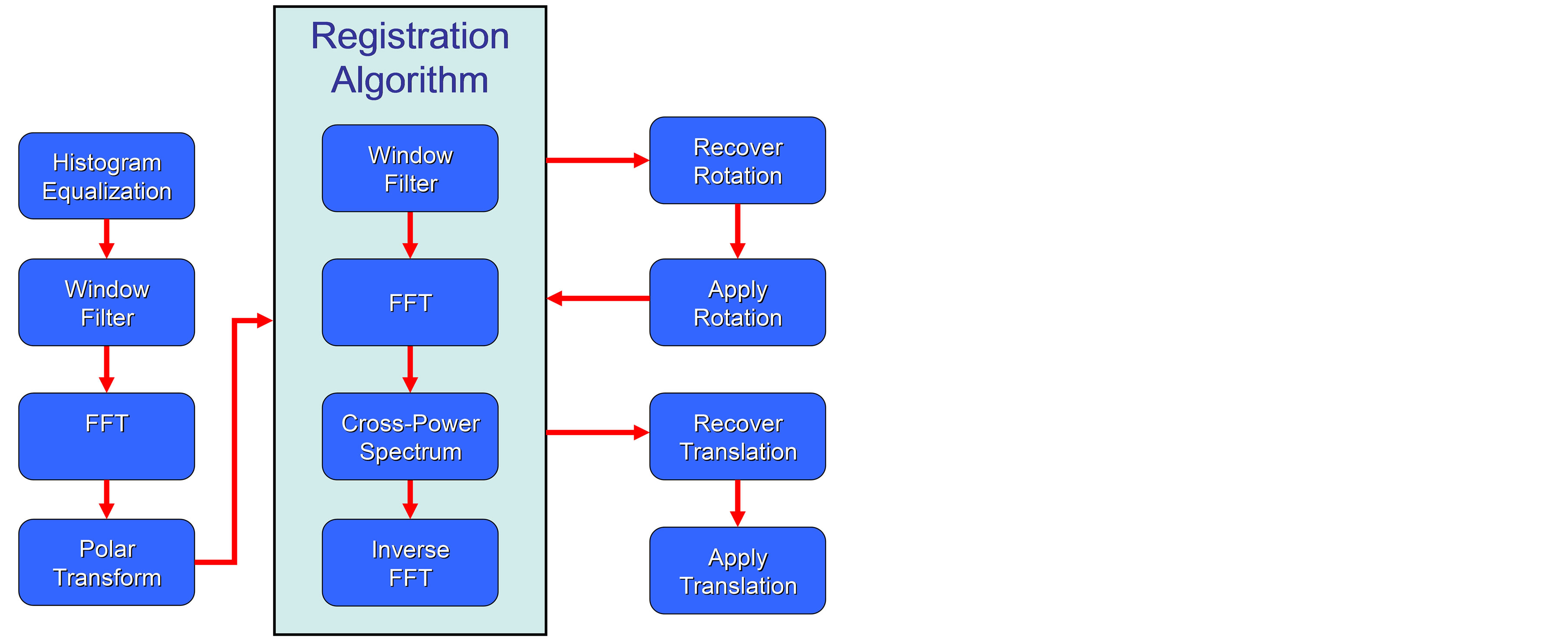
Figure 1. This flowchart illustrates the steps used to register two kV images. First, rotational differences in the images are isolated using the Fast Fourier Transform. A polar transform is then performed to convert this rotation into a translation, and then the registration algorithm is used to recover this rotation. After applying this rotation to the image to be registered, the registration algorithm is again used to recover the translational shifts.
j was chosen to be 2. Applying a widened Hanning window to an image results in pixel values that are less disturbed in the center of the image, when compared to an unmodified Hanning window, while still smoothing the edges of the image in order to reduce spectral leakage. An example of applying this modified Hanning window to a clinical kV image can be seen in Figure 2.
Next, the FFT was applied to the images to isolate any rotational shift. The FFT of a windowed kV image can be seen in Figure 3. It should be noted that the FFT will have the high frequency components in the center of the image and the low frequency components near the edges. However, it is common to shift the low frequency components to the center of the image, which has been done in this figure.
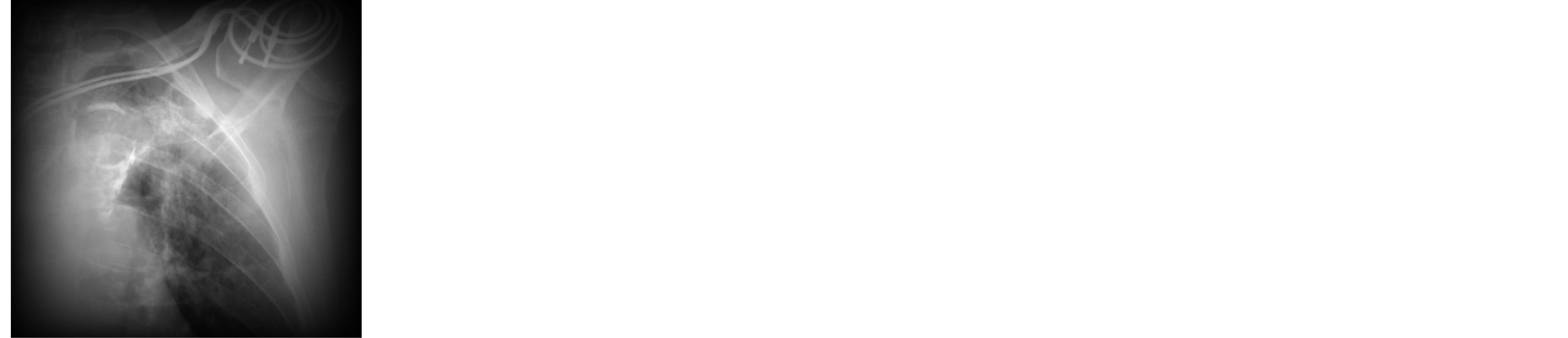
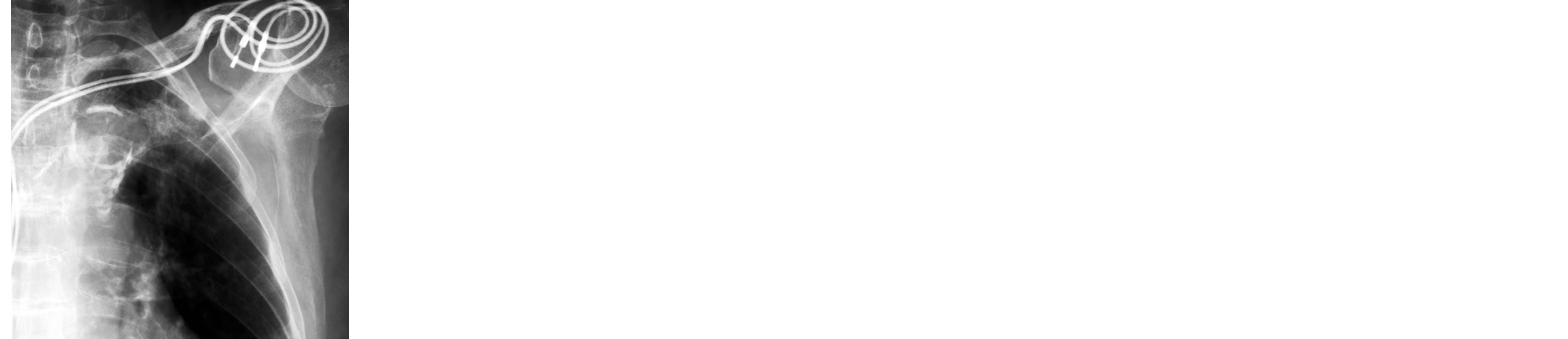
Figure 2. A visual example of applying a modified Hanning window to a kilovoltage image. On the left is the image before the window is applied; on the right is the image after the window is applied. Note that the size of the window can and should be adjusted as required. The best results will occur when the window eliminates the effects of spectral leakage but leaves as much of image data as close to its original pixel values as possible.
Figure 3. The Fast Fourier Transform (FFT) of a windowed kilovoltage image. The low frequency components of the FFT have been shifted to the center of the image. Note that some contrast enhancement was needed to produce this image, as the intensity of the image near the origin is much greater than the surrounding pixels.
The rotational difference between the two FFT images was then converted into a translational shift by performing a polar transformation. Figure 4 shows an example of the polar transformation of the FFT shown in Figure 3. By restricting the polar transformation to a 180 degrees section of the image it is possible to double the effective angular resolution while still maintaining enough information needed to register the images (assuming rotations of less than 90 degrees).
After the rotational parameters were recovered and applied to the underlying image pair, the same registration algorithm was used to recover the translational shifts.
This algorithm was initially evaluated using a simple 512 × 512 reference image, consisting of a 128 × 128 square with a uniform pixel value placed in the middle of the image and set against an empty background. A second floating image was created by inducing a selected set of shifts and rotations to this reference image. An example of this is shown in Figure 5. The range of induced shifts was ±20 pixels in both the x and y directions, and the range of induced rotations was ±10 degrees. The
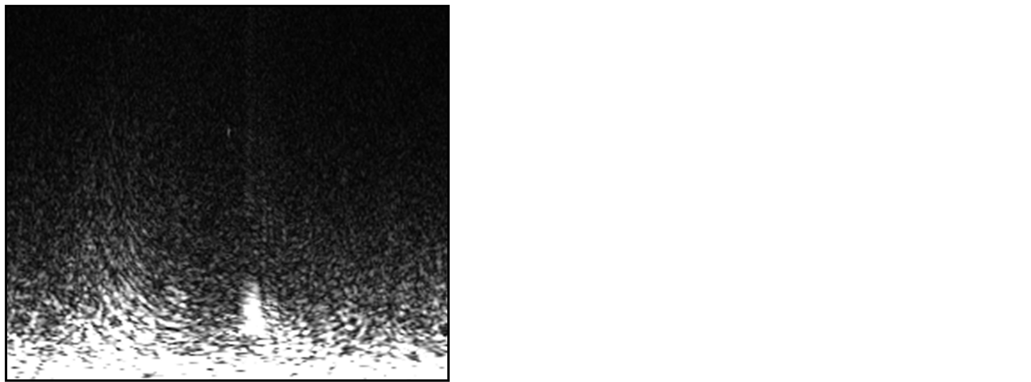
Figure 4. The polar transformation of the top half of the Fast Fourier Transform shown in Figure 3. A modified Hanning window will still need to be applied to this image before it is used in the registration algorithm.


Figure 5. On the left is a simple reference image, consisting of a square with a uniform pixel value set against an empty background. On the right is this same image with an induced shift and rotation.
floating image was then registered to the reference image, using the image registration algorithm described above.
Based on the successful results of this trial (discussed below), the registration algorithm was then tested on a set of 1024 × 768 clinical kV images drawn from several different body sites obtained using a Varian On-Board Imager (Varian Medical Systems, Palo Alto, CA, USA). The body sites chosen were head and neck, thorax, abdomen and pelvis. Two orientations were used for each body site—one anterior and one lateral. For each image, twenty-five uniformly distributed random sets of translations and rotations were generated. The range of these induced shifts was ±20 mm in both the x and y directions, and ±10 degrees. After these shifts and rotations were applied, each image was cropped to 512 × 512 in order to eliminate the artifacts introduced by these artificial shifts. In total, 200 different rotational and translational displacements were induced across eight different images.
3. Results
The registration parameters returned by the registration algorithm for the image consisting of a simple square as shown in Table 1.
In this general case, translational shifts were applied in integer values of pixels and rotations in integer values of degrees. Examining Table 1, we can see that the registration algorithm correctly recovered the applied shifts with no error, and correctly recovered the rotational shifts within 0.2 degrees. It should be noted that the discrete nature of the registration algorithm presented here limits the accuracy of the algorithm to the pixel size of the image description (For an example of an algorithm designed for sub-pixel registration, see [18]). For this simple image the effective pixel resolution is 1, while the angular resolution of algorithm is determined by the number of rows or columns (depending on the axis choice for θ) used to create the polar transformed image; for a 512 × 512 image the angular resolution is 0.352 degrees. This means there is an uncertainly in the registration algorithm equal to half these resolutions; i.e. 0.5 pixels and 0.176 degrees. Re-examining the error in Table 1, we see these values fall within the uncertainty of the algorithm.
The results of the algorithm using clinical kV images are summarized in Table 2. The kV images used in this trial had a pixel spacing of 0.256 mm in the x and y
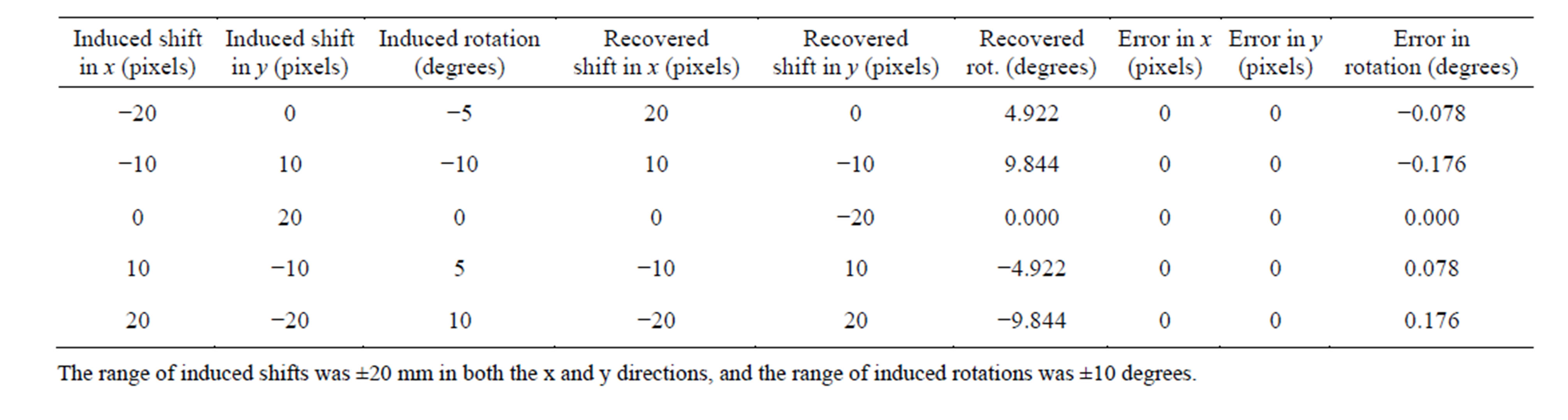
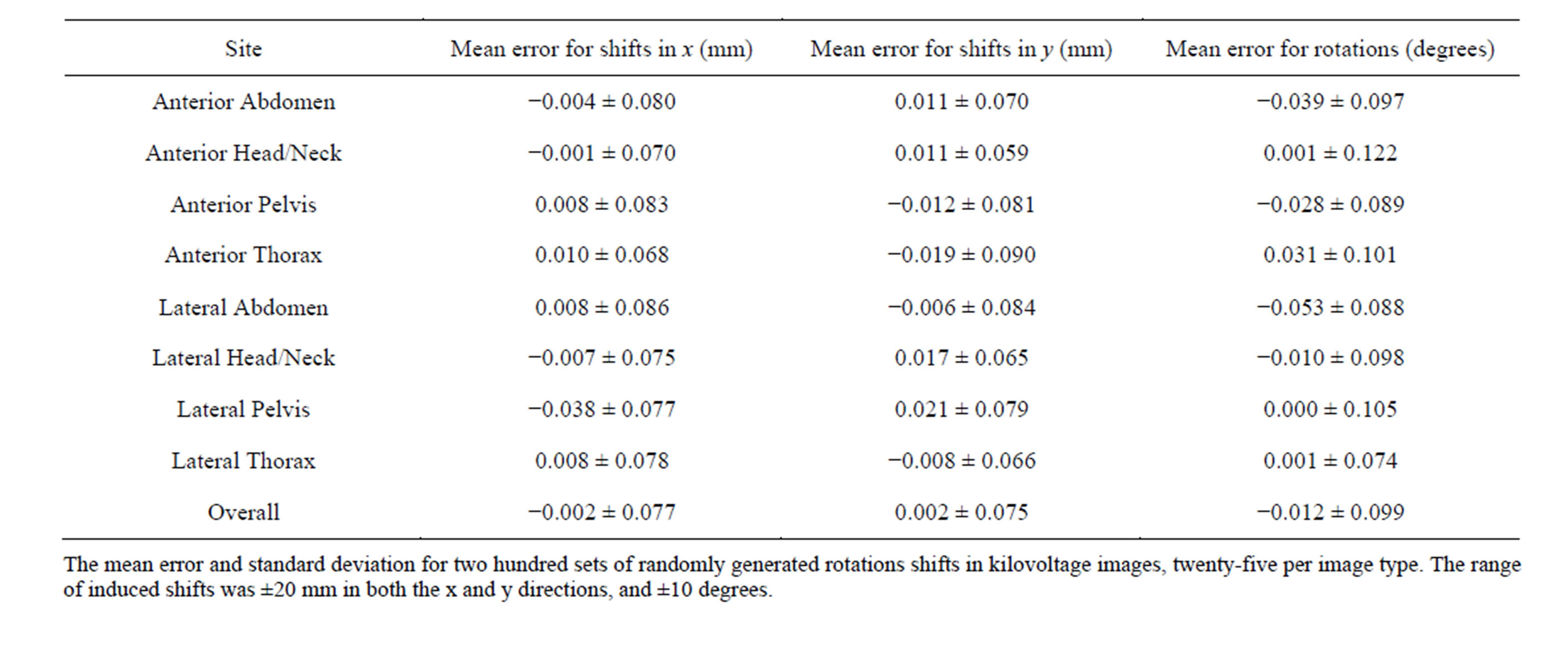
Table 2. Induced and recovered shifts for clinical images.
directions (with no change in the angular resolution), which corresponds to an uncertainly in the registration algorithm of 0.128 mm and 0.176 degrees, for translations and rotations, respectively. The mean error and standard deviation for the shifts and rotations for each subcategory of kV images are shown, as well as the overall results for all 200 registrations. The mean error of the solutions generated by this algorithm reveals if there is any bias in the algorithm, while the standard deviation demonstrates the accuracy of the algorithm.
Examining Table 2, we see that the largest mean error among the different categories of images was −0.038 mm for lateral pelvic images and −0.053 degrees for lateral abdominal images. These values are small in comparison to the resolution of the images, indicating that if any bias exists in this algorithm it is likely to be negligible. The largest standard deviations were ±0.090 mm for AP thoracic images and ±0.122 degrees for AP head/neck images. Since these values are smaller than the uncertainty inherent to the algorithm, these results suggest that an FFT-based algorithm has a high degree of accuracy when registering clinical kV images across multiple body sites and orientations.
4. Discussion
This study examines the use of a FFT based algorithm for medical image registration in radiotherapy, as was first explored by Wang et al. In this earlier study, the authors focused on improving the accuracy of the translational solution for a small selection of pelvic portal images. In our study, we evaluated this algorithm on kV images used for daily image guidance. More importantly, unlike the previous study, our method incorporates a technique [7] for determining rotations in addition to translations.
There are several advantages to using a FFT based image registration algorithm in the radiotherapy setting. Many commonly used methods for medical image registration, such as MI, rely on an iterative method for finding optimal registration parameters [3,4]. However, it is not uncommon for this kind of algorithm to fall into a local minimum or maximum. This occurs when the registration parameter being minimized or maximized has crossed a chosen threshold but is not at the desired solution, resulting in misregistration. The FFT registration algorithm, which is based on image cross-correlation, is not iterative or threshold based and so does not share this risk.
In addition, image registration using a FFT-based algorithm is relatively fast. Specifically, the FFT provides a computationally efficient method for transforming an image to the frequency domain; assuming an N × N image, the computational time needed to compute a FFT is on the order of Nlog(N) [19,20]. As mentioned previously, performing cross-correlations in the frequency domain significantly reduces the number of calculations required. Therefore, it is almost always faster to calculate the normalized cross-power spectrum in the frequency domain, including the computational time needed to perform the FFT and its associated inverse FFT, than to perform cross-correlation in the spatial domain.
On a Dell Optiplex 755, with an Intel® Core™2 Duo CPU E8400 at 3.00 GHz with 3.00 GB of RAM, the average time to register a 512 × 512 image was approximately 0.08 sec. In addition, this speed may be increased substantially through the use of a Graphics Processing Unit (GPU). A GPU consists of hundreds of individual processing units that can work in parallel to compute a matrix operation in tandem faster than a single CPU can compute it sequentially. When using a GPU, any matrixwide operation, such as the FFT, can see a significant decrease in the time needed for its calculation [21]. Since the FFT accounts for a significant amount of the computational time needed by the CPU to perform the registration algorithm, it is expected that implementation on a GPU would provide a substantial speedup to this method, particularly when used on larger images and/or three dimensional images [22].
As one might expect, this algorithm is not without limitations. The basis of this algorithm, the Fourier shift theorem, requires that the two images be identical to each other except for their spatial displacement. In practice, it is unlikely that any two medical images that are to be registered will be perfectly identical. There are likely to be small differences in the images due to noise in the imaging environment, although previous studies have shown that FFT based algorithms are fairly robust against these kinds of image variations [6,7]. However, significant differences between the two images to be registered will be problematic. For example, it is expected that images with significant amounts of deformation will cause, at least, partial misregistration. In addition, this algorithm may not be well suited for images taken across different modalities, such as CT vs. MR. In these cases, some additional image processing may be necessary prior to the use of this algorithm. Further studies are being conducted to evaluate the clinical utility of this image registration approach.
5. Conclusion
We present here a FT-based image registration algorithm. This algorithm is computationally efficient and provides a high degree of accuracy for rigid registration. This algorithm provides a distinct analytic solution, and does not rely on iterative methods to converge to a solution. Finally, if used in conjunction with a GPU, a FT-based registration algorithm has the potential to perform extremely fast medical image registration.
REFERENCES
- J. B. A. Maintz and M. A. Viergever, “An Overview of Medical Image Registration Methods,” UU-CS, Vol. 22, 1998, pp. 1-22. http://dspace.library.uu.nl/handle/1874/18921
- M. V. Wyawahare, P. M. Patil and H. K. Abhyankar, “Image Registration Techniques: An Overview,” Vol. 2, No. 3, 2009, pp. 11-27.
- J. P. W. Pluim, J. B. A. Maintz and M. A. Viergever, “Mutual Information Based Registration of Medical Images: A Survey,” IEEE Transactions on Medical Imaging, Vol. 22, No. 8, 2003, pp. 986-1004. http://dx.doi.org/10.1109/TMI.2003.815867
- F. Maes, D. Vandermeulen and P. Suetens, “Medical Image Registration Using Mutual Information,” Proceedings of the IEEE, Vol. 91, No. 10, 2003, pp. 1699- 1722. http://dx.doi.org/10.1109/JPROC.2003.817864
- J. P. Lewis, “Fast Normalized Cross-Correlation,” In: Vision Interface, 1995, pp. 120-123.
- B. S. Reddy and B. N. Chatterji, “An FFT-Based Technique for Translation, Rotation, and Scale-Invariant Image Registration,” IEEE Transactions on Image Processing, Vol. 5, No. 8, 1996, pp. 1266-1271. http://dx.doi.org/10.1109/83.506761
- H. Xie, N. Hicks, G. R. Keller, H. Huang and V. Kreinovich, “An IDL/ENVI Implementation of the FFT-Based Algorithm for Automatic Image Registration,” Computers & Geosciences, Vol. 29, No. 8, 2003, pp. 1045-1055.
- E. De Castro and C. Morandi, “Registration of Translated and Rotated Images Using Finite Fourier Transforms,” IEEE Transactions on Pattern Analysis and Machine Intelligence, Vol. PAMI-9, No. 5, 1987, pp. 700-703. http://dx.doi.org/10.1109/TPAMI.1987.4767966
- R. Joshi and R. Cook, “An Analysis of Rigid Image Alignment Computer Vision Algorithms,” International Journal of Computer and Electrical Engineering, Vol. 1, No. 1, 2012, pp. 48-54.
- J. Z. Wang, L. E. Reinstein, J. Hanley and A. G. Meek, “Investigation of a Phase-Only Correlation Technique for Anatomical Alignment of Portal Images in Radiation Therapy,” Physics in Medicine and Biology, Vol. 41, No. 6, 1996, pp. 1045-1058. http://dx.doi.org/10.1088/0031-9155/41/6/008
- A. Papoulis, “Systems and Transforms with Application in Optics,” McGraw-Hill, New York, 1968.
- G. D. Bergland, “A Guided Tour of the Fast Fourier Transform,” IEEE Spectrum, Vol. 6, No. 7, 1969, pp. 41- 52.
- G. Tzimiropoulos and T. Stathaki, “Robust FFT-Based Scale-Invariant Image Registration,” 4th SEAS DTC Technical Conference, Edinburgh, 7-8 July 2009, A10.
- F. J. Harris, “On the Use of Windows for Harmonic Analysis with the Discrete Fourier Transform,” Proceedings of the IEEE, Vol. 66, No. 1, 1979, pp. 51-83.
- M. Sedlacek and M. Titera, “Interpolations in Frequency and Time Domains Used in FFT Spectrum Analysis,” Measurement, Vol. 23, No. 3, 1998, pp. 185-193. http://dx.doi.org/10.1016/S0263-2241(98)00031-1
- J. Schmidt and K. Creath, “Window Function Influence on Phase Error in Phase-Shifting Algorithms,” Applied Optics, Vol. 35, No. 28, 1996, pp. 5642-5649. http://dx.doi.org/10.1364/AO.35.005642
- J. Cooley and J. Tukey, “An Algorithm for the Machine Calculation of Complex Fourier Series,” Mathematics of Computation, Vol. 19, No. 90, 1965, pp. 297-301. http://dx.doi.org/10.1090/S0025-5718-1965-0178586-1
- E. Vera and S. Torres, “Subpixel Accuracy Analysis of Phase Correlation Registration Methods Applied to Aliased Imagery,” 16th European Signal Processing Conference, Lausanne, 25-29 August 2008, 5p.
- R. Yavne, “An Economical Method for Calculating the Discrete Fourier Transform,” AFIPS Fall Joint Computer Conference, Vol. 33, 1968, pp. 115-128. http://dl.acm.org/citation.cfm?id=1476610
- T. Beth, “On the Computational Complexity of the General Discrete Fourier Transform,” Theoretical Computer Science, Vol. 51, No. 3, 1987, pp. 331-339. http://dx.doi.org/10.1016/0304-3975(87)90041-7
- R. Shams, P. Sadeghi, R. A. Kennedy and R. I. Hartley, “A Survey of Medical Image Registration on Multicore and the GPU,” IEEE on Signal Processing Magazine, Vol. 27, No. 2, 2010, pp. 50-60.
- G. Xuejun, H. Pan, Y. Liang, R. Castillo, D. Yang, D. Choi, et al., “Implementation and Evaluation of Various Demons Deformable Image Registration Algorithms on a GPU,” Physics in Medicine and Biology, Vol. 55, No. 1, 2010, pp. 207-219. http://dx.doi.org/10.1088/0031-9155/55/1/012