Journal of Applied Mathematics and Physics
Vol.05 No.09(2017), Article ID:79087,8 pages
10.4236/jamp.2017.59142
Friction Shear Stress on the Surface of Iron-Based Coating/HSS during Sliding Wear of Pin Disk
Huajun Wang, Kangkang Gan, Xiaoguang Zhou, Songshan Yan, Longfei Niu
School of Materials Science and Engineering, Wuhan University of Technology, Wuhan, China


Received: July 4, 2017; Accepted: September 12, 2017; Published: September 15, 2017
ABSTRACT
With the increasing demand for lightweight and lower fuel consumption and safety of automobile industry, lightweight materials of high strength steel (HSS) are more and more widely used. The hot stamping technology, which is determined by the inherent mechanical properties of high strength steel, makes molds prone to wear failure in the harsh service environments. In this paper, a finite element model is proposed for analyzing the value and distributions law of friction shear stress of contact surface of the pin disk. Through the simulation process of sliding wear, two kinds of different cladding materials of the pin specimens including H13 and Fe65, were experimented under three different loads by using the software ABAQUS. And then the pin-on- disk wear test at elevated temperature was conducted to verify the effectiveness of the simulation results. The results showed that the friction shear stress of pin with iron-based cladding and H13 steel was different under different loads, but the distribution was basically the same; the normal friction shear stress increased gradually along the direction of the pin movement, and the tangential shear stress increased gradually from the center of the pin to the outside of the circle; the value of the friction shear stress of the normal joints on the contact surface was periodically fluctuating in the whole dynamic analysis step, while it was basically stable in the tangential direction.
Keywords:
High Strength Steel, Iron-Based Cladding, Sliding Wear, Friction Shear Stress, Finite Element Analysis

1. Introduction
With the requirement of reducing automobile weight for energy saving, the application of high strength steel (HSS) on automobile has been popularized increasingly, due to not only achieving weight reduction of automobile, but improving the passive safety. Achievements of lightweight automobile projects abroad in recent years are summarized, especially about development of high strength steel sheets [1].
In general, with the enhancement of steel blank’s mechanical strength, its formability is worsened dramatically. It is difficult to apply the traditional cold stamping technology into the field of pressing HSS [2]. Thus, the hot stamping technology of HSS is applied as a new technology, which combines cold stamping process and heat treatment process to solve the difficult forming problem of HSS by using the plastic strengthening property of the sheet metal under high temperature [3]. Compared with the cold stamping die, the working conditions of the hot stamping die are worse, the wear of the mold is more serious, the service life of the die and the quality of the stamping parts will also be reduced [4] [5]. With the extended use of the mold cycle, the die surface of high temperature has been damaged by friction for a long time, which will inevitably cause the wear and tear of the die. At present, in the mold industry, the surface coating technology is applied to prepare the super alloy coating on the surface of the mold, which can effectively improve the wear resistance of the mold surface, and improve the service life of the mold greatly [6] [7]. Various techniques such as PVD and CVD have been applied to the cladding of the wear resistant layer on the die surface. Among the advanced techniques, powder plasma surfacing technology is one of the most promising process because its dense structure and better coating performance and especially for its wide range of material selection [8]. And the iron-based cladding alloys are extensively used in the industry for sliding wear application. They possess high resistance to wear and plastic deformation at temperature in excess of 600˚C [9].
At present, there are few researches on the wear of hot forming dies, and most of them focus on experimental research. However, the cost is high, and some physical quantities are difficult to measure in the experiment [9] [10]. The Finite element Simulation, as a supplementary method, is mainly aimed at stimulating the physical quantity which is difficult to measure in the process of experiment, such as interfacial compressive stress, friction shear stress and temperature field in the process of wear test. Therefore, it is of great practical significance to carry out the numerical simulation of the wear of the hot forming die [11]. In this paper, combined with the hot stamping process conditions of high strength steel, the test parameters of the pin-on-disk in the high temperature wear test were used to simulate the value and distribution of the shear stress on the contact surface during the wear process, Which provided a theoretical basis for the determination of stress concentration area and wear area in wear process.
2. Finite Element Modeling of the Pin Disk
2.1. The Establishment of the Pin-Disk Model
Figure 1 shows the pin-disk wear model Established in ABAQUS. The size of the pin and the disk is the same as that of the high-temperature friction and wear test. The size of the disk is Φ58 × 8 mm, the shape of the pin is irregular, and the rotational radius r of the pin to the center of the disk is 20 mm during sliding wear. The material of the disk is DP600.
2.2. Related Parameter Setting
The Simulation parameter of the pin-on-disk model is listed in Table 1. The top surface of the disk is the main surface, For the face, the disk is bound into a rigid body, while the pin is not bound, and the friction coefficient corresponding to the different load is selected according to the result of the high temperature friction and wear test.
The static general analysis step named move is set to achieve relative rotation of the pin with analysis time of 1 s and the maximum incremental step of 1000. The initial and maximum value of the incremental step is set at 0.01and 0.05 respectively. In the load setting, the concentrated force of 100 N, 150 N, and 200 N is applied to the top of the pin.
The role of analysis step move is to generate relative rotation under the stable contact, therefore, the analysis of the contact in the pin boundary conditions set at U1 = U2 = 0, the action area selects the side of the pin. Disk boundary conditions Set at V1 = V2 = V3 = VR1 = VR2 = 0, VR3 = 8.37758 rad/s, the action area selects the rigid body constraint control point of the disk, where VR3 is comes from the friction test.
3. Results and Discussion
The simulation analysis is used to analyze the friction shear stress in the tangential direction of the vertical normal motion and the parallel motion in the step.
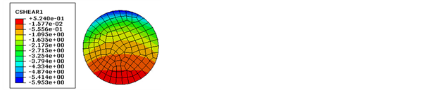
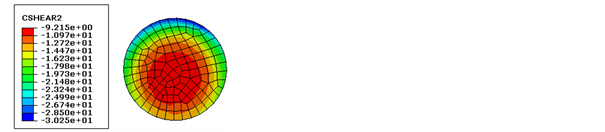
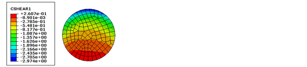
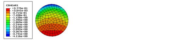
Figures 2-4 show the distribution profiles of the friction shear stress of the pin with iron-based cladding under the loads of 100 N, 150 N and 200 N,

Figure 1. Finite element model of Pin-disc.

Table 1. Simulation parameter of the pin-on-disk model.
 (a)
(a)
 (b)
(b)
Figure 2. Friction shear stress distribution of the pin with iron-based cladding under 100 N load.
 (a)
(a)
 (b)
(b)
Figure 3. Friction shear stress distribution of the pin with iron-based cladding under 150 N load.
 (a)
(a)
 (b)
(b)
Figure 4. Friction shear stress distribution of the pin with iron-based cladding under 200 N load.
respectively, Where (a) is the normal friction shear stress, and (b) is the tangential friction shear stress
From Figures 2-4, it can be seen that the instantaneous direction of the linear velocity of the pin relative to the disk movement is the positive direction of the Y axis, and the distribution law of the friction shear stress in the normal and tangential directions under different loads is basically the same. The normal friction shear stress increases gradually along the direction of the pin movement, while the tangential shear stress increases gradually from the center of the pin to the outside of the circle, and it reach the maximum at the edge of the sliding direction, which is up to about 3 times the minimum friction shear stress at the same time, and the overall value of the friction shear stress increases with the increase of applied load.
Figures 5-7 show the distribution profiles of the friction shear stress of the
 (a)
(a)
 (b)
(b)
Figure 5. Friction shear stress distribution of the pin without cladding under 100 N load.
 (a)
(a)
 (b)
(b)
Figure 6. Friction shear stress distribution of the pin without cladding under 150 N load.
 (a)
(a)
 (b)
(b)
Figure 7. Friction shear stress distribution of the pin without cladding under200 N load.
pin without cladding under the loads of 100 N, 150 N and 200 N, respectively, where (a) is the normal friction shear stress, and (b) is the tangential friction shear stress.
From Figures 5-7, it can be seen that the distribution of friction shear stress on the contact surface of pin without cladding is basically the same as that of pin with iron-based cladding, but the value is vary with the friction coefficient and material properties.
Figure 8 and Figure 9 show the variation curve of frictional shear stress with simulated time in the normal and tangential steps of the three nodes at the uppermost, middle and lowest ends of the iron-based cladding surface under 200 N load.
From Figure 8 and Figure 9, it can be seen that the value of the friction shear

Figure 8. Friction shear stress-time curves of normal direction.

Figure 9. Friction shear stress-time curves of tangential direction.
stress in each node in the normal direction fluctuates periodically in the whole dynamic analysis step, while it is basically the same in the tangential direction.
4. Wear Test Results
To verify the effectiveness of the simulation results, the pin-on-disk wear test at elevated temperature were conducted with the pin of Fe65 cladding. Figure 10 shows the macroscopic topography of the pin with Fe65 cladding under 200N load. Figure 11 shows the SEM image of the Fe65 cladding under 200N load, with a magnification of 50.
From the previous simulation results, it can be seen that the distribution law of the friction shear stress in the tangential direction is the middle is small while the margin is large, and the decreasing direction is consistent with the sliding direction. In Figure 10 and Figure 11, the scratched direction is consistent with the sliding direction, and the edge of the pin has severe oxidation wear, while the middle part is lighter, Which coincides with the distribution of frictional forces in the simulation results, to a certain extent, the test has proved the simulation.

Figure 10. Macro wear morphology.

Figure 11. The whole SEM image of Fe65.
5. Conclusions
As has been discussed in the previous sections, the sliding wear process of the pin disk was simulated and analyzed by using the software ABAQUS. From these results, the following conclusions can be reached.
1) The friction shear stress of pin with iron-based cladding and H13 steel is different under the different loads, but the distribution is basically the same.
2) The normal friction shear stress increases gradually along the direction of the pin movement, and the tangential shear stress increases gradually from the center of the pin to the outside of the circle, and it is greatest at the front margin of the moving direction, which is up to about 3 times the minimum friction shear stress at the same time.
3) The value of the friction shear stress of the normal joints on the contact surface is periodically fluctuating in the whole dynamic analysis step, and the magnitude of the shear stress in the tangential direction is basically stable in the whole dynamic analysis step.
Acknowledgements
This work has been carried out with financial support from Natural Science Foundation of China (51475346) and the authors gratefully acknowledge their support. The authors gratefully acknowledge the assistance of Dr. Ainong Li in the experimental work.
Cite this paper
Wang, H.J., Gan, K.K., Zhou, X.G., Yan, S.S. and Niu, L.F. (2017) Friction Shear Stress on the Surface of Iron-Based Coating/HSS during Sliding Wear of Pin Disk. Journal of Applied Mathematics and Physics, 5, 1694-1701. https://doi.org/10.4236/jamp.2017.59142
References
- 1. Li, Y., Lin, Z., Jiang, A. and Chen, G. (2003) Use of High Strength Steel Sheet for Lightweight and Crashworthy Car Body. Materials & Design, 24, 177-182. https://doi.org/10.1016/S0261-3069(03)00021-9
- 2. Zhang, Y., Lai, X., Zhu, P. and Wang, W. (2006) Lightweight Design of Automobile Component Using High Strength Steel Based on Dent Resistance. Materials & Design, 27, 64-68. https://doi.org/10.1016/j.matdes.2004.09.010
- 3. Yildirim, H.C., Marquis, G. and Sonsino, C.M. (2015) Lightweight Potential of Welded High-Strength Steel Joints from s700 under Constant and Variable Amplitude Loading by High-Frequency Mechanical Impact (hfmi) Treatment. Procedia Engineering, 101, 467-475. https://doi.org/10.1016/j.proeng.2015.02.056
- 4. Fu, Z.K., Ding, H.H., Wang, W.J., Liu, Q.Y., Guo, J. and Zhu, M.H. (2015) Investigation on Microstructure and Wear Characteristic of Laser Cladding Fe-Based Alloy on Wheel/Rail Materials. Wear, 330-331, 592-599. https://doi.org/10.1016/j.wear.2015.02.053
- 5. Zhang, L., Sun, D., Hongying, Y.U. and Huiqi, L.I. (2007) Characteristics of Fe-Based Alloy Coating Produced by Plasma Cladding Process. Materials Science & Engineering A, 457, 319-324. https://doi.org/10.1016/j.msea.2006.12.047
- 6. Liu, S., Bor, T.C., Stelt, A.A.V.D., Geijselaers, H.J.M., Kwakernaak, C., Kooijman, A.M., et al. (2016) Friction Surface Cladding: An Exploratory Study of a New Solid State Cladding Process. Journal of Materials Processing Technology, 229, 769-784. https://doi.org/10.1016/j.jmatprotec.2015.10.029
- 7. Skare, T. and Krantz, F. (2003) Wear and Frictional Behaviour of High Strength Steel in Stamping Monitored by Acoustic Emission Technique. Wear, 255, 1471-1479. https://doi.org/10.1016/S0043-1648(03)00197-2
- 8. Pereira, D., Gandra, J., Pamies-Teixeira, J., Miranda, R.M. and Vilaça, P. (2014) Wear Behaviour of Steel Coatings Produced by Friction Surfacing. Journal of Materials Processing Technology, 214, 2858-2868. https://doi.org/10.1016/j.jmatprotec.2014.06.003
- 9. Liu, X.B., Pang, M., Zhang, Z.G., Tan, J.S., Zhu, G.X. and Wang, M.D. (2012) Numerical Simulation of Stress Field for Laser Thermal Loading on Piston. Optics & Laser Technology, 44, 1636-1640. https://doi.org/10.1016/j.optlastec.2011.12.045
- 10. Zhang, Y.F., Sun, Z.J. and Yuan, Z. (2012) Wear Characteristics Analysis of Pin-On-Disc Pairs Based on Finite Element Model. Applied Mechanics & Materials, 148-149, 806-809.
- 11. Bortoleto, E.M., Rovani, A.C., Seriacopi, V., Profito, F.J., Zachariadis, D.C., Machado, I.F., et al. (2013) Experimental and Numerical Analysis of Dry Con-tact in the Pin on Disc Test. Wear, 301, 19-26. https://doi.org/10.1016/j.wear.2012.12.005