Journal of Applied Mathematics and Physics
Vol.05 No.09(2017), Article ID:79077,10 pages
10.4236/jamp.2017.59136
Liquefied Natural Gas Tanks for Suppressing Pitching Motions of FLNG Facility
Wenshou Zhang, Jian Cheng, Yaoquan Duan
State Key Laboratory of Structural Analysis for Industrial Equipment, International Research Center for Computational Mechanics, Dalian University of Technology, Dalian, China


Received: June 18, 2017; Accepted: September 12, 2017; Published: September 15, 2017
ABSTRACT
Floating liquefied natural gas (FLNG) facility using partially filled tanks for control of pitch motion response to wave-exciting forces is investigated in this paper. The governing equations for sloshing analysis of rectangular tanks under pitch motion excitation are first established, then the spatial (boundary- value) partial derivatives are approximated by finite differences. The uncoupled pitch equation of FLNG is derived by assuming that pitch is uncoupled from other modes of vibration. By using state-space model to represent fluid-memory effect, the pitch equation can be transformed to first- order ordinary differential equations which can be solved with sloshing equations simultaneously with the given initial conditions. By using the proposed coupling model for FLNG facility and the liquefied natural gas (LNG) tanks, the performance of partially filled tanks for suppressing pitching motions of FLNG facility is numerically assessed. The parametric studies on the example FLNG show that there is a beneficial filling level by which the pitch motion of FLNG can be considerably reduced.
Keywords:
FLNG, Sloshing, Coupled Analysis, Pitching Motion, Hydrodynamics

1. Introduction
Floating liquefied natural gas (FLNG) facility represents a new technology with a promising future in the offshore oil industry, which combines the production, storage, transportation with a liquefied natural gas (LNG) liquefaction unit. The LNG liquefaction equipment used in FLNG facility will suffer considerable wave-induced motions which appear within a wide range of sea states and lasts for almost the whole design life of the FLNG facility. As a result, the frequent occurrence of the wave-induced motions of the FLNG facility of relatively large amplitude may cause low efficiency of liquefaction process or malfunction of the equipment. Hence, it is of practical interest to reduce excessive wave-induced motions of the FLNG facility.
The FLNG facility which is moored directly above the natural gas field possesses a number of large LNG tanks. A single point mooring (SPM) mechanism allows FLNG to rotate or weathervane freely with respect to a fixed mooring point and pitch motions play an important role in FLNG hydrodynamic responses. The wave-induced motions of the FLNG facility may cause severe sloshing in a partially filled tank and, in turn, the sloshing in the tank impacts the motions of the FLNG facility. The coupling effect between the sloshing in the tank and the FLNG facility motion is of a great concern to the FLNG operation in the production site and offloading operation of LNG carriers close to FLNG facility. Malenica et al. presented an efficient method for dynamic coupling between sloshing and seakeeping in frequency domain [1]. Kim et al. studied the coupling effects of ship motion and sloshing. The linear ship motion was solved using an impulse-response function (IRF) method and the nonlinear sloshing flow was simulated using a finite-difference method [2]. Zhao et al. investigated the coupling effects between ship motions and internal sloshing by using scaled model tests [3]. Jiang et al. analyzed the coupling effect between ship motion response and internal sloshing flow based on OpenFOAM [4]. All the aforementioned research activities focus on the slosh-induced impact pressures and the ship motion responses.
A tuned liquid damper (TLD), which usually is a rigid tank partially filled with water in it, is a kind of passive control device relying upon liquid sloshing to suppress structural vibration. TLDs have been investigated and used as economical and effective dynamic vibration absorbers to mitigate the dynamic response of structures for decades [5] [6] [7] [8]. They are found effective in suppressing horizontal motion of buildings and structures. However, only a little information is available at present on how to mitigate pitching motion of structures. Sun et al. utilized the TLD for suppressing pitching motion of structures and demonstrated the TLD to be an effective means in suppressing pitching vibration [9]. Koh et al. presented a study on the behaviour of rectangular liquid dampers under arbitrary excitations and showed that significant suppression of structural vibration could be achieved using tuned liquid dampers [10]. Compared with suppressing horizontal motion, the research on suppression of pitching motion is relatively limited.
In this paper, a coupling model for FLNG facility and the LNG tanks is proposed. By using partially filled tanks as TLDs, the suppression of pitch motion of FLNG facility is investigated. The convolution term representing fluid-memory effect associated with the dynamics of the radiation forces is represented by the corresponding state-space model. Using finite differences to approximate the spatial partial derivatives in the continuity and Navier-Stokes equations, the Partial Differential Equations are transformed to the associated ordinary differential equations. Based on the derived formulae, the performance of partially filled tanks for suppressing pitching motion of FLNG facility is numerically assessed. It is found that if the filling level, i.e. the liquid depth, is selected suitably, the pitching motion of FLNG can be considerably reduced.
2. Mathematical Formulation
2.1. Sloshing Problem
The FLNG facility considered in this study is equipped with n rectangular shaped LNG tanks. Each tank is partially filled with an incompressible and viscous liquid. The ith liquid tank is characterized by the liquid density , the length , width and liquid height . Some right-handed Cartesian coordinate systems are introduced to facilitate the formulation of the coupling problem. XYZ-system with origin at the center of gravity (COG) of the ship and Z axis pointing vertically upwards in quiescent water is used as a ship-fixed coordinate system for ship motion analysis. -system is the ith tank-fixed coordinate system with origin at the geometrical center of the free surface of the tank.
The continuity and Navier-Stokes equations in the ith tank-fixed coordinate system are [9] [10]
(1)
(2)
where the subscript denotes the ith tank, is the fluid velocity along the direction at the free surface, is the free-surface displacement, and are the - and -coordinates of the origin of the -system in the XYZ-system, is the pitch angle of the tank, , , in which is the wave number; , in which is the kinematic viscosity coefficient and is the characteristic frequency of liquid motion, which may be taken as the natural frequency of the liquid tank, is taken as unity.
The boundary conditions at the wall of the tank can be expressed as
(3)
The initial conditions for the liquid at rest initially are
(4)
The pressure is expressed approximately as [9]
(5)
where
(6)
The moment about the COG of the ship due to liquid sloshing is calculated as
#Math_30# (7)
2.2. Ship Motion
The equations of motion for coupled sloshing and ship motion can be expressed as follows:
(8)
where are the linear external wave force and moment components, are the force and moment components associated with sloshing; are the displacements of the ship motion; , and are, respectively, the components of the generalized mass, infinite-frequency added mass, and restoring matrices of the ship, are the retardation functions.
For simplicity, we assume that pitch is uncoupled from other modes of vibration although there are coupling effects between the vertical and longitudinal motions (heave, pitch, surge) of the ship. The uncoupled pitch equation can now be expressed as
#Math_39# (9)
where denotes the linear external wave excitation pitch moment, denotes the moment associated with sloshing in the ith tank, is the ship's moment of inertia in pitch, is the infinite-frequency added mass in pitch, is the restoring coefficient in pitch, is the retardation function in pitch. The calculation of retardation function for pitch can be given by noting the relationships [11]:
#Math_46# (10)
(11)
in which and are added mass and damping coefficients in pitch, respectively.
The convolution integral in Equation (9) is known as fluid-memory effect and denoted by , i.e.
. (12)
Applying a Laplace transform to both sides of Equation (12), one obtains
(13)
where , and are the Laplace transforms of , and , respectively.
Ogilvie showed that the following frequency-domain representation holds for the retardation function [11]
. (14)
Hence, can be approximated by relative degree one transfer function [12]
(15)
As a result, can be represented by the corresponding state-space model of the following form:
(16a)
(16b)
where is a state vector, , and are constant matrices and given by
, ,#Math_71# (17)
Combining Equations (7), (9) and (16) yields
(18)
where
, (19)
in which
, #Math_76# (20)
(21)
(22)
(23)
(24)
The spatial (boundary-value) partial derivatives in Equations (1) and (2) are approximated by finite differences. The difference equations with the given initial conditions are then solved simultaneously with Equations (18) using the Runge-Kutta method.
3. Numerical Results
For application, a SPM FLNG as shown in Figure 1 is selected as an example for parametric study. The main dimensions of the FLNG are given in Table 1. To make the problem manageable, all the tanks have been lumped into two equivalent and identical tanks. The centers of the bottom of the two tanks are located at (−69, 0, −11.5) and (69, 0, −11.5) in the XYZ-system, respectively. The parameters of the tank are given in Table 2.
The irregular waves are generated using the JONSWAP spectra defined as

Figure 1. A schematic diagram of single point mooring FLNG.

Table 1. Main dimensions of the FLNG.
Table 2. Parameters of the tanks.
#Math_82# (25)
where , , is the significant wave height,
and is the peak period. Figure 2 shows the JONSWAP spectrum for , . The wave excitation pitch moment RAO are complex variable and expressed as:
(26)
where and are the pitch moment RAO amplitude and phase for frequency . The amplitude and phase of pitch moment RAO are shown in Figure 3.
The time history of wave excitation pitch moment can be obtained from the corresponding RAO and JONSWAP spectrum using a series of trigonometric functions
#Math_93# (27)
where is frequency interval, is the corresponding random phase angle which uniformly distributed over the interval . Using equation (27), a typical simulated time history of pitch moment is calculated and shown in Figure 4, with its time duration and time interval is 60 s and 0.005 s, respectively.
Figure 5 shows the raw added mass and damping , together with the corresponding fitting results. The order of the approximation is in Equation (15). The infinite-frequency added mass coefficients is also
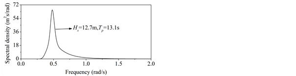
Figure 2. JONSWAP spectrum.


Figure 3. RAO and phase of pitch moment of the FLNG.

Figure 4. Time history of pitch moment.


Figure 5. Added mass and damping for pitch.
estimated and plotted in Figure 5. As seen from this figure, the fitting is relatively good.
To investigate the performance of partially filled tanks for suppressing pitching motion of the FLNG, the pitch responses of the FLNG are computed against different liquid heights. Then, by comparing the results among all the pitch responses, the beneficial liquid height can be found for achieving the maximum or beneficial pitch response reduction of the FLNG with reasonable sloshing force. This study selects h of 8.09 m as a beneficial value for the hydrodynamic response analysis using the derived formulae. Figure 6 shows the time histories of the pitch response of the FLNG with and without liquid sloshing. Clearly, liquid heights of the tanks affect the pitch response of the FLNG. It is seen from the figure that the maximum pitch angle of the FLNG is 3.70 degree without liquid sloshing. For the beneficial liquid height m, the maximum pitch angle of the FLNG is 2.65 degree, leading to a 28.4% reduction of the pitch response.
4. Conclusion
Liquid sloshing inside the tanks of FLNG has been used for suppressing pitching motion of the FLNG. By using state-space model to represent the fluid-memory effect, a mathematical formulation is derived for coupled sloshing and ship motion analysis. The wave excitation pitch moment is generated using a series of trigonometric functions based on RAO amplitude and phase of the pitch moment and wave spectra. With the derived formulae, extensive parametric studies have been performed on the coupled system to seek beneficial liquid heights for maximum pitch response reductions with reasonable sloshing forces. It was

Figure 6. Time history of pitch angle with and without TLD.
found that if liquid heights are selected appropriately, the pitch response of the FLNG could be considerably reduced.
Acknowledgements
The authors wish to acknowledge the financial support from the Project supported by No. 11572072 and National High Technology Research and Development Program of China (863 Program), No. 2014AA09A224.
Cite this paper
Zhang, W.S., Cheng, J. and Duan, Y.Q. (2017) Liquefied Natural Gas Tanks for Suppressing Pitching Motions of FLNG Facility. Journal of Applied Mathematics and Physics, 5, 1638-1647. https://doi.org/10.4236/jamp.2017.59136
References
- 1. Malenica, S., Zalar, M. and Chen, X.B. (2003) Dynamic Coupling of Seakeeping and Sloshing. Proceedings of the Thirteenth International Offshore and Polar Engineering Conference, Honolulu, Hawaii, 25-30 May 2003, 486-492.
- 2. Kim, Y., Nam, B.W., Kim, D.W. and Kim, Y.S. (2007) Study on Coupling Effects of Ship Motion and Sloshing. Ocean Engineering, 34, 2176-2187. https://doi.org/10.1016/j.oceaneng.2007.03.008
- 3. Zhao, W.H., Yang, J.M., Tao, L.B. and White, D. (2014) Research on the Coupling Effects between Ship Motions and Sloshing. Proceedings of the ASME 33rd International Conference on Ocean, Offshore and Arctic Engineering, San Francisco, California, 8-13 June 2014, OMAE2014-23846. https://doi.org/10.1115/OMAE2014-23846
- 4. Jiang, S.C., Teng, B., Bai, W. and Gou, Y. (2015) Numerical Simulation of Coupling Effect between Ship Motion and Liquid Sloshing under Wave Action. Ocean Engineering, 108, 140-154. https://doi.org/10.1016/j.oceaneng.2015.07.044
- 5. Fujino, Y., Sun, L., Pacheco, B.M. and Chaiseri, P. (1992) Tuned Liquid Damper (TLD) for Suppressing Horizontal Motion of Structures. Journal of Engineering Mechanics, ASCE, 118, 2017-2030. https://doi.org/10.1061/(ASCE)0733-9399(1992)118:10(2017)
- 6. Banerji, P., Murudi, M., Shah, A.H. and Popplewell, N. (2000) Tuned Liquid Dampers for Con-trolling Earthquake Response of Structures. Earthquake Engineering & Structural Dy-namics, 29, 587-602. https://doi.org/10.1002/(SICI)1096-9845(200005)29:5%3C587::AID-EQE926%3E3.0.CO;2-I
- 7. Tait, M.J. (2008) Modelling and Preliminary Design of a Structure-TLD System. Engineering Structures, 30, 2644-2655. https://doi.org/10.1016/j.engstruct.2008.02.017
- 8. Malekghasemi, H., Ashasi-Sorkhabi, A., Ghaemmaghami, A.R. and Mercan, O. (2015) Experimental and Numerical Investigations of the Dynamic Interaction of Tuned Liquid Damper-Structure Systems. Journal of Vibration and Control, 21, 2707-2720. https://doi.org/10.1177/1077546313514759
- 9. Sun, L.M., Fujino, Y. and Koga, K. (1995) A Model of Tuned Liquid Damper for Suppressing Pitching Motions of Struc-tures. Earthquake Engineering & Structural Dynamics, 24, 625-636. https://doi.org/10.1002/eqe.4290240502
- 10. Koh, C.G., Mahatma, S. and Wang, C.M. (1994) Theoretical and Experimental Studies on Rectangular Liquid Dampers un-der Arbitrary Excitations. Earthquake Engineering & Structural Dynamics, 23, 17-31. https://doi.org/10.1002/eqe.4290230103
- 11. Ogilvie, T. (1964) Recent Progress to-ward the Understanding and Prediction of Ship Motions. Proceedings of the 5th Sym-posium on Naval Hydrodynamics. Bergen, 10-12 September 1964, 3-80.
- 12. Perez, T. and Fossen, T. (2008) Joint Identification of Infinite-Frequency Added Mass and Fluid-Memory Models of Marine Structures. Modeling, Identification and Control, 29, 93-102. https://doi.org/10.4173/mic.2008.3.2