International Journal of Communications, Network and System Sciences
Vol.10 No.08(2017), Article ID:78384,10 pages
10.4236/ijcns.2017.108B010
A Non-Maximally Decimated Dynamic Reconfigurable Channelized Structure Based on Modulated Filter Bank
Wenxu Zhang, Wentong Zhao, Junxi He, Fangming Shi
Information and Communication Engineering College, Harbin Engineering University, Harbin, China


Received: May 17, 2017; Accepted: August 11, 2017; Published: August 14, 2017
ABSTRACT
A structure of dynamic reconfigurable channelized filter bank is proposed in order to solve the problem that the uniform channelized receiver cannot receive the cross-channel and wideband signal. The dynamic reconfigurable channelized filter bank is divided into two parts-the analysis filter bank and the synthesis filter bank. The function of the analysis filter bank is to divide the received signal into several sub-signals according to the channel division. Then the sub-signals of each channel need to be detected and discriminated. At last, we use the sub-signals to reconstruct the original received signal by the synthesis filter bank. The analysis filter and the synthesis filter bank of the dynamic reconfigurable channelized filter bank are all efficient polyphase structures, so it can save more hardware resources and has extensive applicability. The structure is simulated by MATLAB and the simulation results verify the correctness of this structure.
Keywords:
Dynamic Reconstruction Channelization, Analysis Filter Bank, Synthesis Filter Bank, Modulated Filter Bank

1. Introduction
With the development of software radio, the digital channelized receiver has become a hot spot research in the field of receiver. It has the advantages of digital receiver such as high accuracy, high flexibility, high reliability, low power consumption, and meanwhile the advantages of channelized receiver such as good applicability and strong comprehensiveness. The digital channelized receiver divides the instantaneous bandwidth into several sub-band channels by the digital filter bank. When the receiver receives the instantaneous signal, it can realize the full-probability receive through processing the sub-band signals in parallel.
Reference [1] proposes many different structures of synthesis filter bank according to the different band allocations. Reference [2] is mainly used in communication system. The frequency of the received signal has narrow dynamic range and its range is generally known in advance. Reference [3] shows that the transition band of the filter in analysis filter bank should be narrow enough so that the aliasing between the sub-bands will not happen and the analysis filter bank can satisfy perfect reconstruction condition.
In this paper, we propose a non-maximally decimated dynamic reconfigurable channelized structure based on the modulated filter banks. The received signal firstly goes through the decimation module to reduce the sampling rate, and then is divided into several sub-band signals by the analysis filter bank. Secondly, the sub-band signals go through the detection and discrimination module. Finally, the synthesis filter bank reconstitutes the desired signal by synthesis the sub-band channels with signal. This method can synthesis the channels with sub-band signals, which reduces the consumption of hardware resources.
2. Signal Perfect Reconstruction Condition
Figure 1 shows us the M-channel non-maximum decimated filter bank [4].  is the input signal.
  is the z-transform of the frequency response of the k-th filter of the analysis filter bank.
The M filters evenly divide the entire frequency band into M sub-bands.  is the center frequency of the k-th filter, so the z-transform of the frequency response of the k-th filter is
 ,
, .
.  is the z- transform of the frequency response of prototype low-pass filter. The input signal firstly goes through the analysis filter bank, and it is divided into D sub-band signals by the analysis filter bank. Then do detection and discrimination to the output of the analysis filter bank and sent the detected D sub-band signals to the synthesis filter bank. The sub-band signals will be K times interpolated. Then we use the synthesis filter bank to filter out the redundant mirror bandwidth caused by interpolation. The outputs of the synthesis filter are summed so that we can get the desired signal. The z-transform of the frequency response of k-th filter of

Figure 1. M-channel non-maximum decimated filter bank.
the synthesis filter bank is , and
, and  is the z-transform of the frequency response of prototype low-pass filter of the synthesis filter bank.
  is the z-transform of the frequency response of the detecting and processing sector between the analysis and synthesis filter banks. In this way, the z-transform of the frequency response of the output of the synthesis filter bank
  can be expressed as:
 (1)
(1)
As Equation (1) can be expressed in matrix form, we define the following column vectors:
 (2)
(2)
 (3)
(3)
 (4)
(4)
 (5)
(5)
 (6)
(6)
 (7)
(7)
Then, the matrix representation of Equation (1) can be written as:
 (8)
(8)
The total z-transfer function of the system can be expressed as:
 (9)
(9)
The desired signal z-transfer function can be expressed as:
 (10)
(10)
The undesired aliasing z-transfer function can be expressed as:
 (11)
(11)
Then we can rewrite Equation (8) as:
 (12)
(12)
Let , then the undesired aliasing signal can be completely cancelled:
 (13)
(13)
So, the aliasing cancellation condition can be expressed as:
 (14)
(14)
By the theory of the modulation filter bank, the aliasing cancellation condition can be expressed as:
 (15)
(15)
In order to achieve the aliasing cancellation condition, Equation (10) is required to be the integer delay of the analysis and synthesis filter bank and the z-transform of the frequency response of the detecting and processing sector .
.
Above all, the desired signal z-transform function can be expressed as [5]:
 (16)
(16)
In order to achieve the desired signal perfect reconstruction condition without the detecting and processing sector, the modulation filter bank must satisfy Equations (15) and (16).
3. The Analysis Filter Bank
The low-pass structure uniform analysis filter bank [6] is shown in Figure 2. The number of the channel is M. The multiple of the decimation is K and . The input signal firstly goes through the down-conversion module to become a baseband signal. And then filter the baseband signal to get the sub-band signals. At last, we decimate these sub-band signals. When the number of the channel is large, it is very difficult to complete engineering realization. Assume that the order of the low-pass filter is N, so the total order of this whole structure is
 . As the number of the channel increases, the total order also increases, so the consumed multiplier and adder resources increase. The complex exponential down-conversion module requires the resource of the multiplier and adder, so when the number of the frequency band increases the required resources will also increase. The decimation module can reduce the sampling rate, but in this structure the decimation module is at the end of the system. So, the down-conversion

Figure 2. The low-pass structure of the analysis filter bank.
module and the low-pass filter are in a high sampling rate. If the system processes the signal at a high sampling rate, the hardware requirements will be relatively increased.
In order to solve these problems, we use the efficient polyphase structure of the analysis filter bank to replace this structure. We can infer the efficient polyphase structure of the analysis filter by doing polyphase decomposition to the low-pass structure. Through the theory of IDFT and polyphase filtering, we can get the efficient polyphase band-pass structure of the analysis filter bank as shown in Figure 3.
The z-transform function of the output of the IDFT module
 can be expressed as:
 (17)
(17)
Then the z-transform function of the output of the k-th channel can be expressed as:
 (18)
(18)
Because , so the z-transform function of the k-th channel can also be expressed as:
 (19)
(19)
Then the output signal can be expressed as:
 (20)
(20)
When we put the decimation module in front of the IDFT module, the signal  can be expressed as:
 (21)
(21)
The z-transform function of  can be expressed as:
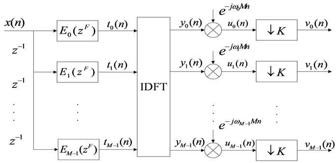
Figure 3. The efficient polyphase band-pass structure of the analysis filter bank.
 (22)
(22)
Because ,
,  is an integer and
 , so Equation (22) can be rewritten as:
 (23)
(23)
From the above deduction, we can get the improved efficient polyphase structure as shown in Figure 4.
4. The Synthesis Filter Bank
The low-pass structure of the synthesis filter bank was shown in Figure 5. We can also use the polyphase decomposition method to infer the efficient polyphase structure from the low-pass structure [7].
Assuming that the input signal occupies P sub-band channels, the number of the channel of the input signal of the synthesis filter bank Q should satisfy: , where
  represents the nearest integer from x. Under the condition of signal perfect reconstruction, the number of the channel of the synthesis filter bank is M and the multiple of the decimation is K. The number of the channel of the input signal of the synthesis filter bank Q and the times of the in-

Figure 4. The improved efficient polyphase structure of the analysis filter bank.

Figure 5. The low-pass structure of the synthesis filter bank.
terpolation K should satisfy the following formula:
 (24)
(24)
From Figure 5, we can know that the output of the synthesis filter bank  can be expressed as:
 (25)
(25)
where 
Let  and then:
 (26)
(26)
 (27)
(27)
Let , so the output signal can be expressed as [8]:
 (28)
(28)
Let , so:
, so:
 (29)
(29)
Because K is even, so Equation (29) can be expressed as [9]:
 (30)
(30)
where  is the F times decimation of
 .
.
 (31)
(31)
From the corollary in Reference [1], we can know that when the number of the channel of the synthesis filter bank is M and the times of the decimation is M/Q we can get the synthesis filter that satisfy the perfect reconstruction condition:
 (32)
(32)
In order to save the hardware resources further, we should improve this structure by using the dynamic reconstruction method [9]. We can use the FFT module in the synthesis filter bank. Secondly, we can just synthesize the sub- band channel with signal.
When the output of the analysis filter bank occupies  channel, where
 . We just need to input the
  sub-band signals, where
 . When
 , we begin at the first channel. When
 , we begin at the second channel.
The z-transform function of the output of the k-th synthesis filter  can be expressed as:
 (33)
(33)
Because , so:
, so:
 (34)
(34)
Assuming  is even,
  can be divided into two parts:
 (35)
(35)
The first part of the Equation (35) is desired signal; the second part is undesired aliasing. So, we know that even if the perfect reconstruction condition is met, the output signal cannot be completely synthesized. We defined that . So, the output signal of the synthesis filter bank
  can be
  times decimated, and the aliasing condition will not happen. According to the theory of the integer multiple interpolation, the times of the decimation K can be shifted. When
  is an integer, the interpolation module can be expressed as
 . When
  is not an integer, the interpolation module is 0. Let
 , so we can get the dynamic reconstruction synthesis filter bank shown as Figure 6. The synthesis filter should satisfy the following condition:
 (36)
(36)
5. Simulation
Firstly, we need to design the prototype filter. The pass-band cut-off frequency

Figure 6. The improved efficient polyphase structure of the synthesis filter bank.
of the prototype filter is 60 MHz and its stop-band cut-off frequency is 90 MHz. The order of the prototype filter is 127. The sampling rate is 960 MHz, and the number of channel is 8. The decimation time is 4. We input two signals. One is a chirp complex signal from 80 - 160 MHz and the other is a chirp complex signal from 340 - 400 MHz. The first signal occupies the first and second channels and the second signal occupies the third and the 4th these two channels. From the simulation result we can prove the correctness of this structure. The frequency spectrum of the input signals and the output signals are shown in following Figures 7-8.

Figure 7. The frequency spectrum of the input.


Figure 8. The frequency spectrums of the output signal 1 and 2.
6. Conclusion
This paper aimed to solve the problem that the analysis filter bank of the digital channelized receiver cannot receive the cross-channel signal proposes a dynamic reconstruction channelized structure based on uniform channelization. This structure improves the aliasing problem caused by the analysis filter bank and satisfies the perfect reconstruction condition. Because this structure can reduce the design complexity of the filter, when the hardware resource is limited this structure has more advantages.
Acknowledgements
This work is supported partly by National Natural Science Foundation of China under Grant No. 61301205 and No. 61571146, National Defense Based Science Research Program under Grant No. JCKY2013604B001. This paper is funded by the International Exchange Program of Harbin Engineering University for Innovation-oriented Talents Cultivation.
Cite this paper
Zhang, W.X., Zhao, W.T., He, J.X. and Shi, F.M. (2017) A Non-Maximally Decimated Dynamic Reconfigurable Channelized Structure Based on Modulated Filter Bank. Int. J. Communications, Network and System Sciences, 10, 88-97. https://doi.org/10.4236/ijcns.2017.108B010
References
- 1. Zhang, W.X. (2009) Research and Implementation of Digital Channelized Receiver in Passive Radar Seeker. Ph.D. Thesis, Harbin Engineering University, Harbin.
- 2. Li, B., Zheng, J. and Ge, L.D. (2007) Dynamic Channelization Based on NPR Modulated Filter Banks. Acta Electronica Sinica, 35, 1178-1182.
- 3. Zhu, X. and Feng, X.C. (2009) A Efficient Dynamic Digital Channelizer. Journal of Harbin Institute of Technology, 41, 160-164.
- 4. Nguyen, T.Q. and Vaidyanathan, P.P. (1990) Architectures for M-Channel Perfect- Reconstruction FIR QMF Banks Which Yield Linear-Phase Analysis and Syn-thesis Filters. IEEE Transactions ASSP, 38, 433-446. https://doi.org/10.1109/29.106862
- 5. Chen, X.F., Harris, F.J., Venosa, E. and Rao, B.D. (2014) Non-Ma Non-Maximally Decimated Analysis/Synthesis Filter Banks: Applications in Wide-band Digital Filtering. IEEE Transactions on Signal Processing, 62, 852-866. https://doi.org/10.1109/TSP.2013.2295549
- 6. Vaidvanathan, P.P. (2001) Filter Banks in Digital Communications. IEEE Circuit and System Magazine, 1, 4-25.
- 7. Chen, T., Yue, W., Liu, Y.Q. and Si, X.C. (2011) Research on Partial Channel Reconstruction Technology Based on a Wide-Band Digital Channelized Receiver. Jour- nal of Harbin Engineering University, 32, 1610-1616.
- 8. Gong, S.X., Wei, X.Z. and Li, X. (2013) Review of Wideband Digital Channelized Receivers. ACTA Electronicasinica, 41, 949-958.
- 9. Gao, X.G. and Zuo, Y. (2015) A Wide-Band Signal Reconfiguration Method Based on Improved Channelized Architecture. Electronic Information Warfare Technology, 30, 63-67.