Int. J. Communications, Network and System Sciences, 2011, 4, 638-647
doi:10.4236/ijcns.2011.410078 Published Online October 2011 (http://www.SciRP.org/journal/ijcns)
Copyright © 2011 SciRes. IJCNS
Beam Selection and Antenna Selection: A Hybrid
Transmission Scheme over MIMO Systems Operating with
Vary Antenna Arrays
Feng Wang, Marek E. Bialkowski
School of Information Technology and Electrical Engineering, University of Queensland Brisbane, Brisbane, Australia
E-mail: {fwang, meb}@itee.uq.edu.au
Received July 31, 2011; revised August 24, 2011; accepted September 15, 2011
Abstract
In this paper, we have proposed a hybrid transmission scheme which involves beam selection and antenna
selection techniques over a MIMO system operating with vary antenna array. Optimal subset of transmit an-
tennas are selected via fast successive selection scheme designed to optimize the target eigenbeam. Optimal
eigenbeams corresponding to the largest singular values of the new MIMO channel formed by the selected
antennas are exploited for data transmission. To evaluate the performance of the proposed scheme, different
array structures, including uniform linear array (ULA) and including uniform circular array (UCA) are em-
ployed in the simulations. The transmitter is assumed to be surrounded by scattering objects while the re-
ceiver is postulated to be free from scattering objects. The Laplacian distribution of angle of arrival (AoA) of
a signal reaching the receiver is postulated. The results presented by this paper indicate that the proposed
scheme can significantly improve the performance of data transmission in term of symbol error rate (SER).
Keywords: MIMO, Beam Selection, Antenna Selection, ULA, UCA
1. Introduction
In recent years, wireless multiple-input multiple-output
(MIMO) systems featured by employing multiple anten-
nas at the transmitter and receiver have attracted constant
attention. Research has revealed that MIMO is capable of
improving system capacity and link robustness signifi-
cantly in a rich scattering environment without costing
extra transmit power and bandwidth [1-3]. The data
transmission schemes over a MIMO channel can be
categorized into three types. The first one is multiplexing
gain maximizing schemes, which are exploited to trans-
mit independent data streams in parallel through multiple
spatial channels. Bell Labs Layered space-time (BLAST)
techniques [4,5] are typical multiplexing schemes to in-
crease the data rate. The second one is diversity gain
maximizing schemes, which are exploited to combat the
fading effect of wireless channel and improve the bit-
error-rate (BER) performance. To obtain the diversity
gain, the signals carrying the same information are
transmitted through redundant independent fading chan-
nels. As a result, the data transmission reliability is as-
sured. Space-time coding techniques [6,7] are typical
schemes of exploiting spatial diversity. However, maxi-
mizing multiplexing gain may not necessarily maximize
diversity gain and vice versa. Consequently, scholars
also tried to achieve trade-off between the multiplexing
and diversity gain [8].
With the perfect channel state information (CSI), the
optimal design, in terms of maximum data rate is mul-
tichannel beamforming (MB) [9]. This strategy transmits
data on the eigenmodes (or eigenbeams) of the MIMO
channel using linear transmit-receive processing [10,12].
It has been well noted that the eigenmodes corresponding
to the small singular values are showing a poor perform-
ance. Targeting at this problems, power allocating and
bit-loading schemes were proposed in [11]. By allocating
different power and constellations among a subset of
available eigenmodes, a significantly improved perfor-
mance can be achieved. The complexity of such a scheme is
significant since each channel eigenmode requires a dif-
ferent combination of signal constellation and codes,
depending on the allocated power [13]. For this reason,
equal power and bit allocation scheme is still a popular
transmission scheme. With equal power and bit alloca-
tion, an improved performance can also be obtained by
F. WANG ET AL.639
selecting the optimal eigenmodes (which are corre-
sponding to the largest singulars) [9].
Antenna selection (AS) has been proposed for en-
hances performance in correlated fading [14,15]. By se-
lecting a small number of optimal antennas from a large
set of antennas, AS is capable of capturing a large por-
tion of the channel capacity of MIMO [19]. AS also re-
sults in a reduced hardware cost and computational com-
plexity [17]. AS have received a plenty of attentions. A
couple of antenna selection criteria have been studied in
[14]. To avoid the theory-optimal exhaustive search
scheme, fast antennas selection schemes have been pro-
posed [17-19].
In this paper, we proposed a hybrid transmission
scheme over a MIMO system, in where, the optimal ei-
genmodes for the optimal antenna subset are employed
to transmit data. To achieve this goal, a fast antenna se-
lection scheme designed for the eigenbeam selection is
proposed. The performance of the proposed scheme is
evaluated in a spatial correlation fading environment.
Previous researches show that spatial correlation always
has a negative impact on the MIMO performance [21,22].
It can be expected that difference configurations of an-
tenna arrays will result in different spatial correlations of
transmitted and received signals. As a result, the channel
properties between the transmitter and receiver could be
different. In this paper, we select uniform linear array
(ULA) and uniform circular array (UCA) as the objects.
However, it is worthwhile noticing that we can reach
similar conclusions by reasoning the similarity between
UCA and other alike structures such as triangular, square,
pentagonal or hexagonal arrays.
This paper is organised as follows. In Section 2, we
briefly introduce the signal model and channel model
which are used in the rest of the paper. In Section 3, the
hybrid scheme is presented by introducing the eigenbeam
selection scheme with LMMSE receiver and the fast an-
tenna selection scheme designed for the eigenbeam se-
lection scheme. In Section 4, we provide error rate re-
sults to show the performance of the proposed scheme in
spatial correlated fading channels. Conclusions are given
in Section 5.
2. Signal Model
2.1. System Model
Consider a wireless MIMO system employing N transmit
and M receiver antennas, The impulse response for the
MIMO channel can be modeled by a M × N matrix H
with the (m,n)th element containing the complex fading
parameter between the nth transmit and mth receive an-
tenna. The baseband equivalent signal model can be rep-
resented by
rHXn (1)
1M
r is the received signal vector, 1N
X
1M
represents the transmitted signal vector,
nis the
additive white Gaussian noise vector with covariance
matrix given by
†2
nM
E
nnI (2)
We assume that perfect Channel State Information
(CSI) is available for both the receiver and transmitter
sides. The transmitted signal vector can be written as
Xws (3)
where
,,min
NL
N
ML
w is the transmit adap-
tive switching matrix which maps the L modulated data
symbols si (1 i L ) onto the N transmit antennas. The
symbol si is the elements of s, with E {ss} = IL, and
chosen from all possibly signal constellations. X is sub-
ject to the power constraint, which is given by

2
2
s
EtrE
Xww (4)
2.2. Channel Model
We assume that the wireless MIMO link between the
transmitter and receiver is undergoing a flat-fading nar-
row-band fading. The Kronecker model [21] is utilized,
in where the spatial correlations at the transmitter and
receiver are independent and separable. As a result, the
complex channel matrix H can be given as
12 12
R
T
HRGR (5)
where
R
R is the spatial correlation matrix at the re-
ceiver and T represents the spatial correlation at the
transmitter. In a scattering rich signal propagation envi-
ronment, the antenna array is surrounded by scattering
objects. Based on the assumption that these scattering
objects are uniformly distributed in a circle, the correla-
tion experienced by a pair of antennas with large in-
ter-antennas spacing in an array can be written as
R
0
(,)[2() ]RmnJm n
 (6)
On the other hand, if the antenna array is free from
any surrounding objects, the correlations matrices at the
transmitter and receiver sides are subjective to the array
structure. Figure 1 demonstrates the model under con-
sidered, where the receiver are surrounded by uniformly
distributed scatterers and transmitter equipped with ULA
or UCA is located high above ground where there are no
scattering objects. All the antenna elements at receiver
and transmitter have an omni-directional radiation pat-
tern in the azimuth plane. The θ is the central Angle of
Departure (AoD) or Angle of Arrival (AoA), we assume
Copyright © 2011 SciRes. IJCNS
F. WANG ET AL.
Copyright © 2011 SciRes. IJCNS
640



,
21
22
1
Im
e
4sin2
(2 1)
mn
a
lkc
k
R
aa
CJZk
ak 1()




(10)
In the expressions (7)-(10), a is the decay factor related
to the angle spread, specifically, as a increases, the angle
spread decreases. It also decides the normalizing constant
[23]
21 e
la
a
C
(11)
n
J
represents the nth order Bessel function of the
first kind. The parameter α is the relative angle between
the mth and nth elements in a UCA. Let φm and φn repre-
sent the angle of the mth and nth elements in an azimuth
plane, then we have




cos cos
sin
22cos
sin sin
cos
22cos
mn
mn
mn
mn





(12)
Zl and Zc are related to the antenna spacing in ULA and
UCA, they can be expressed as
2d
l
Z
mn
(13)
Figure 1. Signal model of a downlink MIMO multiuser
system.
222cos
c
R
Z

 
mn
(14)
that θ follows the Laplacian distribution. For the case of
ULA, the real and imaginary components of the spatial
correlation parameter between the mth and nth elements
are given as [23]




2
,0 2
22
1
e
Re2cos(2 )
4
a
mnlk l
k
aa
RJZJZ k
ak

(7)




,
21
22
1
Im
e
4s
(2 1)
mn
a
lkl
k
R
aa
CJZ
ak in21k




(8)
The formulas (7)-(10) show that the spatial correla-
tions between two antenna elements in an ULA and UCA
are characterized by a couple of parameters, including
inter-element spacing (d/λ or d/lambda), AoA and decay
factor. Figure 2 shows the spatial correlation between
the antenna 1 and 2 in regards to inter-element spacing
with different decay factors. We can see from Figure 2
that for both ULA and UCA, large decay factors result in
an increased spatial correlation. Figure 3 and Figure 4
are the correlation surface in regards to the inter-element
spacing and AoA. One can see from Figure 3 and Fig-
ure 4 that for a given inter-element spacing, the spatial
correlation in a ULA increase significantly with AoA (it
becomes more apparent when inter-element spacing is
larger than 0.5), while in a UCA the spatial correlation
remains almost constant in regards to AoA.
Similarly, for the case of UCA, the real and imaginary
components of spatial correlation parameter between the
mth and nth elements are given as [23]





,
2
02
22
1
Re
e
2cos
4
mn
a
ckc
k
R
aa
JZJ Zk
ak 2




(9)
3. Beam Selection and Antenna Selection: A
Hybrid Scheme
In this section, we present the ideal of the hybrid trans-
F. WANG ET AL. 641
00.5 11.522.5 3
0
0. 1
0. 2
0. 3
0. 4
0. 5
0. 6
0. 7
0. 8
0. 9
1
d/lam bda
Spatial Correlation
UCA a =3
UCA a= 10
UCA a= 30
ULA a= 3
ULA a= 1 0
ULA a = 3 0
Figure 2. Spatial correlation between antenna 1 and 2 (four-antenna ULA and UCA, AoA = 0°).
0
1
2
3
0
20
40
60
80
100
0
0.2
0.4
0.6
0.8
1
d/lambda
AoA(degrees)
Spatial Correlation
Figure 3. Spatial correlation between antenna 1 and 2 (four-antenna ULA, decay factor = 5).
0
1
2
30
20
40
60
80
10
0
0
0. 2
0. 4
0. 6
0. 8
1
A oA (degrees)
d/lambda
Spatial Correlation
Figure 4. Spatial correlation between antenna 1 and 2 (four-antenna UCA, decay factor = 5).
C
opyright © 2011 SciRes. IJCNS
F. WANG ET AL.
642
mission scheme by introducing beam selection scheme
and antenna selection scheme respectively. Logically, the
design of antenna selection scheme and performance met-
rics is based on beamforming and beam selection scheme.
The beamforming and beam selection scheme are based
on the current channel station information, and the an-
tenna selection scheme is going change the MIMO chan-
nel matrix. Consequently, beamforming and beam selec-
tion is carried out after antenna selection. In our scheme,
beamforming and beam selection is performed at trans-
mitter side, and antenna selection can be implemented at
either transmitter or receiver side.
3.1. Beam Selection Scheme
We assume that antenna selection scheme has finished.
The output of the antenna selection scheme is a new
channel matrix between the transmitter and receiver with
smaller dimensions (smaller number of columns for
transmits antenna selection and smaller number of rows
for receives antenna selection). We represent the new
complex matrix as can be given as .
Without loss of generality, we assume that P Q. As a
result, by applying SVD technique, the complex channel
can be given as
ˆ(,
PQ PMQ N
H)

1
11
ˆ
00
H
PQ
H
PQ
P
d
uu vv
d







UV
HUΣV
 
 
(15)
where(·)H denotes the hermitian operation and dp is the
pth non-negative singular values with d1 d2 ··· dP and
U and V are the left and right unitary matrices, respec-
tively. We have
H
PP
H
QQ


UU I
VV I
(16)
In fact, V is the matrix with all the columns are the ei-
genvectors of , which is related to the eigen-modes
of the MIMO communication channel. The equation (15)
can be written in a different way, which is given as
ˆˆ
H
HH

ˆˆ
HH
HHV VΣΣ
(17)
For transmit beamforming, the optimal beam direc-
tions are along the eigenvectors of the [12]. In
other words, eigen-beamforming [9,12] utilized the ei-
gen-modes of the auto-correlated to transmit
signal symbols. By assuming that there are L (L min (P,
Q)) data streams are being transmitted to the receiver, the
L columns of V corresponding to the L largest ei-
gen-values are selected as the transmitting beamforming
matrix. Consequently, the received signal vector is given
as
ˆˆ
H
HH
ˆ
H
ˆ
H
H
ˆ
s
L
E
N
rHVsn
(18)
By weighting the received signal vector, the estimated
data at the receiver can be defined as
H
sFr
(19)
The error vector then can be given as
ess
(20)
The mean squared error (MSE) matrix will be then de-
fined as the covariance matrix of the error vector, which
can be presented as
ˆˆ
HHH HH
rLL
E


EeeFRFIFHVVHF
n
H
(21)
where
ˆˆ
HH
rLL
RHVVH R
(22)
The MSE of the lth symbol transmitted to the receiver
is the lth diagonal element of E. Given the transmit beam-
forming matrix VL, the optimal receive matrix Fopt is
obtained such that diagonal elements of E are minimized.
This is equivalent to the solve
minmin (),
HH
H
Tr
FF
cEcEcc c
(23)
By setting the gradient of (23) to zero, and particular-
izing c for all the vectors of the canonical base, it follows
that
1
ˆˆ ˆ
HH
optL LnL
FHVVHRHV
(24)
which is the linear minimum MSE (LMMSE) receiver
(Wiener solution). With this choice of linear receive and
transmit filtering, the MIMO channel is decomposed into
L parallel eigenmode sub-channels, with each can be
expressed as
ˆ,1,,
llllll
s
dpsn lL
 (25)
where l
is a constant, which does not affect the re-
ceived sub-channel SNR, pl is the transmit power allo-
cated to the lth subchannel and dl is the lth largest singular
value of . The instantaneous re-
ceived SNR via the lth suchannel is given by
ˆ(,
PQ PMQ N
H)
2
2,1,,
ll
l
n
dp l
L
(26)
Clearly, the overall received SNR can be lower
bounded by
2
2
L
L
overall
n
dp
SNR
(27)
3.2. Antenna Selection Scheme
Equation (27) shows that the received SNR for the
MIMO system with the choice of transmits and receives
C
opyright © 2011 SciRes. IJCNS
F. WANG ET AL.
Copyright © 2011 SciRes. IJCNS
643
matrices is lower bounded by a monotonically increasing
function of the Lth largest singular value of . In the
case that all the singulars are exploited for data transmis-
sion, the received SNR then will be lower bounded by a
monotonically increasing function of the smallest singu-
lar value of , which is confirmed in [14,16]. As a re-
sult, to match the aforementioned beam selection scheme,
the antenna selection scheme in this paper is to seek the
subset of transmit antennas and receive antennas with the
largest Lth largest singular value. An optimal selection
can be achieved by exhaustively searching over all pos-
sible combinations transmit and receive antennas. How-
ever, such an exhaustive search is hardly suitable for
real-time implementation because of prohibitively long
computational time. A number of complexity reduced
antenna selection schemes [17-19] have been proposed,
however these antenna selection schemes are targeting at
maximizing the channel Shannon capacity.
ˆ
H
ˆ
H
In this paper, we utilize the successive selection ap-
proach which was firstly described in [18] in the context
of channel capacity. However, in this paper, the target of
the antenna selection has changed to maximizing the Lth
largest singular value of . Without loss of generality,
we assume that the subset of antenna selection is per-
formed at the receiver side. The receive antenna selection
approach begins with full set of receive antennas avail-
able and then removes one of receive antenna per step. In
each step, the antenna with the smallest contribution to
the Lth largest singular value of the updated channel ma-
trix is removed. This process is repeated until the re-
quired number of antennas remained. This approach can
also be straightforwardly applied to the transmitter an-
tenna selection.
ˆ
H
Assume that we select O (M O L) out of M avail-
able receive antennas. The selection algorithm can be
presented as follows
111
ˆ()
ˆˆ
111
,0
1( ),
()
:[ , ,,, ,];
ˆ:argmin
:[ , ,,, ,];
MN
TTT T
jj MPt
th
jp MPt
TTT T
MPt
pp
Set Pt
for itoMO
for jtoMPt
Update
CalculateSVD overupdated
end
findpLLargestsingular ofG
Update
Update Pt
 
 






GH
Gg ggg
G
Gg ggg
:1
ˆ:
Pt
end
let

HG
(28)
The strategy requires M-O iterations, and the ith itera-
tion requires M-I + 1 space searches. As a result, the size
of the search space is given as
1
1
MO
i
SMi

(29)
which is far less than the one obtained from the ex-
haustive search scheme. For instance, the total search
space for the exhaustive search scheme amounts to 1820
when O = 4 and M = 16, while for the fast search em-
ployed in this paper only 126 iterations are used.
4. Numerical Results
Monto-carol simulations are performed to evaluate the
performance of the proposed scheme in term of sym-
bol-error-rate (SER). QPSK modulation with Gray cod-
ing is used for the data streams. By assuming that a Gray
encoding is employed to map the bits into the constella-
tion point, the bit-error-rate (BER) can be approximately
obtained from SER by
BERSER R
(30)
where R = log2 K is the number of bits per symbol and K
is the constellation size.
Figure 5 shows the SER performance of transmit an-
tenna selection without beam selection. We assume that
LMMSE receiver is employed. For simplicity reason, the
complex Rayleigh channel is utilized in the simulations.
The receiver is equipped with 2 antennas. The number of
RF chains at transmitter is 2, which means 2 optimal
antennas out of all the available antennas will be acti-
vated during data transmission. We can see from Figure
5 that for a give SNR, the SER performance improved
significantly with the transmit antenna pool. When SNR
= 10 dB, the system without antenna selection (2 × 2/2)
achieves SER approximately at 6.5 × 10⁻², however
when we increase the size of transmit antenna pool to 4
and 8, the SER then are decreased to 6.5 × 10⁻³ and 6.5 ×
10–4, respectively.
Figure 6 shows the SER performance of beam selec-
tion without antenna selection. We assume that LMMSE
receiver is employed. Both the receiver and transmitter
are equipped with 4 elements ULA array with in-
ter-element spacing equals to 0.5 λ. Under Rayleigh chan-
nel, there are 4 eigenbeams at most can be exploited for
data transmission. We can see from Figure 6 that for a
give SNR, the SER performance improved significantly
by beam selection. When SNR = 5 dB, the system with-
out beam selection achieves SER approximately at 1.7 ×
10–1. However when we block the worst beams and select
the best beams for data transmission, the SER perform-
ance is significantly improved. The SER is decreased to
5.5 × 10⁻² when the worst eigenbeam is blocked
F. WANG ET AL.
644
01 23 45 6 78 910
10
-4
10
-3
10
-2
10
-1
10
0
SNR(dB)
SER
2 X (2/2 ) MIMO
2 X (2/4 ) MIMO
2 X (2/6 ) MIMO
2 X (2/8 ) MIMO
Figure 5. SER performance of Transmit antenna selection with LMMSE receiver under Gaussian Channel.
0 1 23 45 6 78 910
10
-6
10
-5
10
-4
10
-3
10
-2
10
-1
10
0
SNR(dB)
SER
4 Eigenbeams
3 Eigenbeams
2 Eigenbeams
1 Eigenbeam
Figure 6 . SER performance of beam selection with LMMSE receiver under Rayleigh Channel.
from data transmission, to 5.5 × 10⁻³ when the worst 2
eigenbeams are blocked and to 1.7 × 10⁻⁵ when the worst
3 eigenbeams are blocked.
Figure 7 shows a compare of the SER performances
of proposed scheme with beam selection. The receiver is
equipped with 4 antennas. The transmitter has 4 RF
branches. The results confirm the observations from Fig-
ure 6 that the performance is significantly improved
when the worst beams are deactivated from data trans-
mission. The MIMO system employs all the 4 eigen-
beams show a poor SER performance (stared and dotted
curves). When the 2 optimal eigenbeams out of 4 avail-
able eigenbeams are exploited, the SER is improved
dramatically (circled and up-triangled curves). The im-
proved performance is achieved by sacrificing data rate.
When the number of available antennas (in Figure 7, the
number is 8) is larger than the number of RF branches,
the proposed fast antenna selection scheme can be util-
ized together with beam selection, thus rendering a hy-
brid scheme. It can be seen from Figure 7 that the pro-
posed scheme is capable of achieving a better BER
without sacrificing data rate. When SNR = 10 dB, the
SER is further increased by the proposed scheme from
2.4 × 10⁻² to 1.7 × 10⁻² for UCA and 1.6 × 10⁻³ to 1.3 ×
10–3 for ULA.
Figure 8 and Figure 9 show the SER performance of
hybrid scheme in where beam selection and antenna se-
lection are both employed. We assume that there are 2
data streams to be transmitted. As a result, only 2 eigen-
beams are exploited for data transmission. The receiver
is equipped with a 4-element ULA or UCA. The trans-
mitter has 4 RF chains and is equipped with a ULA with
C
opyright © 2011 SciRes. IJCNS
F. WANG ET AL. 645
0 1 23 45 6 78 910
10
-3
10
-2
10
-1
10
0
SNR(dB)
SER
UCA 4x4 MIMO w/o BS
ULA 4x4 MIMO w/o BS
UCA 4x4 MIMO BS
ULA 4x4 MIMO BS
UCA Proposed Scheme
ULA Proposed Scheme
4 E ig enbeam s ex poi ted
4 opt i m al ant enn as an d
2 opt imal e i genbeams exploi ted
2 opt i m al ei genbeam expl oi t ed
Figure 7. SER performance of the hybrid scheme with LMMSE receiver (AoA = π/6, a = 5).
0 1 23 45 6 78 910
10
-3
10
-2
10
-1
10
0
SNR(dB)
SER
UCA 4X4/ 4 M IMO 2 E i genbeam s
UCA 4X4/ 6 M IMO 2 E i genbeam s
UCA 4X4/ 8 M IMO 2 E i genbeam s
ULA 4X4/4 M IMO 2 Eigenbeam s
ULA 4X4/6 M IMO 2 Eigenbeam s
ULA 4X4/8 M IMO 2 Eigenbeam s
UCA
UL A
Figure 8. SER performance of the hybrid scheme with LMMSE receiver with vary array structures (AoA = π/6, a = 5).
0 1 23 45 6 7 8 910
10
-2
10
-1
10
0
SNR
(
dB
)
SER
ULA 4X4/4 2 ei ge nbeam s
ULA 4X4/6 2 ei ge nbeam s
ULA 4X4/8 2 ei ge nbeam s
UCA 4X4/4 2 ei genbeam s
UCA 4X4/6 2 ei genbeam s
UCA 4X4/8 2 ei genbeam s
C
opyright © 2011 SciRes. IJCNS
Figure 9. SER performance of the hybrid scheme with LMMSE receiver with vary array structures (AoA = π/3, a = 5).
F. WANG ET AL.
646
inter-element spacing equals to 0.5 λ. Transmit antenna
selection and beam selections are performed at transmit-
ter side. We can see from these figures that with extra
antennas the hybrid scheme is capable of improving the
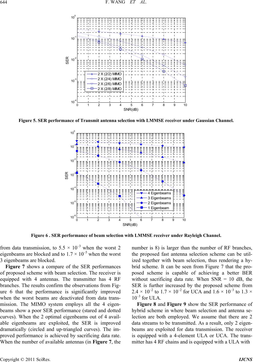
SER performance further. One can see from Figure 8, the
system employing ULA shows a much better perform-
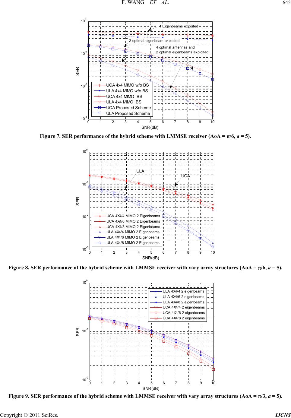
ance when AoA = π/6. However, when AoA increased to
π/3, the system employing UCA takes dominant position
(as shown in Figure 9). By comparing Figure 8 and Fig-
ure 9, it is easy to be noted that the increased AoA leads
to a significant decrease in the SER performance for
ULA. This observation confirms the results shown in
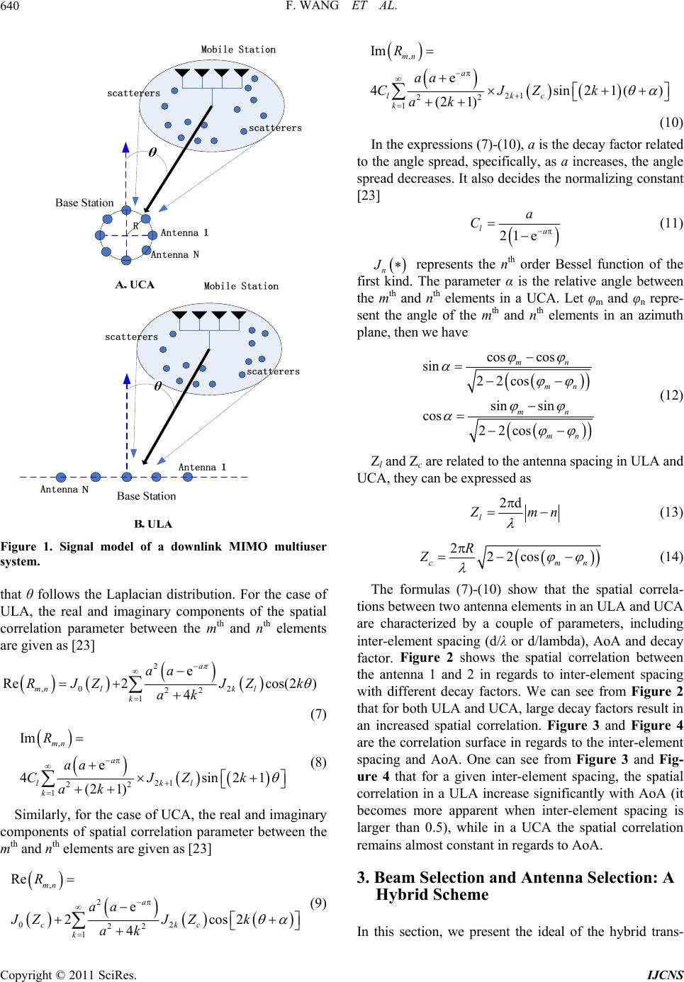
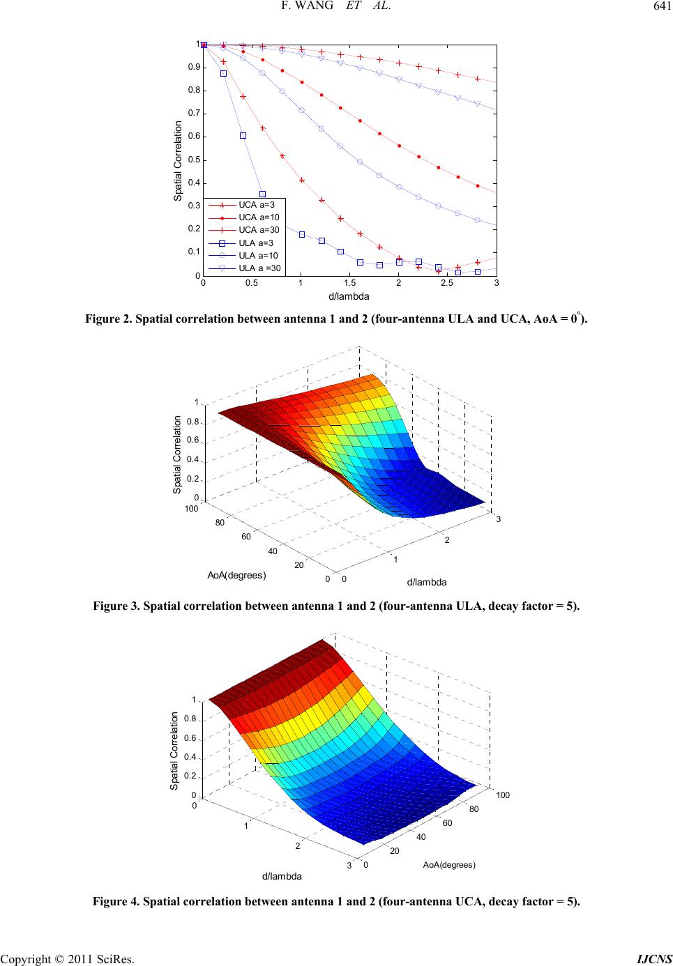
Figures 3 and 4 that a UCA receiver is robust to AoA.
The change of AoA results in little change of SER per-
formance for UCA receievr. On the contrary, the receiver
equipped with ULA is sensitive to AoA. An increased
AoA could result in a significant decrease in the SER
performance.
5. Conclusions
In this paper, we have proposed a hybrid transmission
scheme which involves beam selection and antenna se-
lection techniques over a MIMO system operating with
vary antenna array. Optimal subset of transmit antennas
are selected via fast successive selection scheme de-
signed to optimize the target eigenbeam. Optimal eigen-
beams corresponding to the largest singular values of the
new MIMO channel formed by the selected antennas are
exploited for data transmission. We also evaluated the
performance of the proposed scheme with different array
structures. In our simulations, the transmitter is assumed
to be surrounded by scattering objects while the receiver
is postulated to be free from scattering objects. The
Laplacian distribution of angle of arrival (AoA) of a sig-
nal reaching the receiver is postulated. The results show
that the proposed scheme is capable of achieving an im-
proved SER performance. In regards to the array struc-
ture, we can conclude that ULA is preferred when AoA
is small the constant while UCA is favoured when AoA
is varying significantly.
6. References
[1] G. J. Foschini and M. G. Gans, “On Limits of Wireless
Communications in a Fading Envirmonet When Using
Multiple Antennas,” Wireless Personal Communications,
Vol. 6, No. 3, 1998, pp. 311-335.
doi:10.1023/A:1008889222784
[2] E. Telatar, “Capacity of Multi-Antenna Gaussian Channels,”
European Transactions on Telecommunications, Vol. 10,
No. 6, 1999, pp. 585-596.
doi:10.1002/ett.4460100604
[3] A. Goldsmith, S. A. Jindal and S. Vishwanash, “Capacity
Limits of MIMO Channels,” IEEE Jounal on Selected
Areas in Communications, Vol. 48, No. 3, 2000, pp. 502-
513.
[4] G. J. Foschini, “Layered Space-Time Architecture for
Wireless Communication in a Fading Environment When
Using Multiple Antennas,” Bell Labs Technical Journal,
Vol. 1, No. 2, 1996, pp. 41-59. doi:10.1002/bltj.2015
[5] G. J. Foschini and M. J. Gans, “Capacity When Using
Multiple Antennas at Transmit and Receive Sites and
Rayleigh-Faded Matrix Channel Is Unknown to the
Transmitter,” The Kluwer International Series in Engi-
neering and Computer Science, Vol. 435, No. 4, 2002, pp.
253-267. doi: 10.1007/0-306-47041-1_17
[6] V. Tarokh, N. Seshadri and A. R. Calderbank, “Space-Time
Codes for High Data Rate Wireless Communication: Per-
formance Criterion and Code Construction,” IEEE Trans-
action on Information Theory, Vol. 44, No. 3, 1998, pp.
744-765. doi:10.1109/18.661517
[7] S. Alamouti, “A Simple Transmitter Diversity Scheme
for Wireless Communications,” IEEE Journal on
Selected Areas in Communications, Vol. 16, No. 8, 1998,
pp. 1451-1458. doi:10.1109/49.730453
[8] L. Zhang and D. N. Tse, “ Diversity and Multiplexing: A
Fundamental Tradeoff in Multiple Antenna Channels,”
IEEE Transaction on Information Theory, Vol. 49, No. 5,
2003, pp. 1073-1096. doi:10.1109/TIT.2003.810646
[9] S. Jin, R. McKay, X. Gao and I. B. Collings, “MIMO
Multichannel Beamforming: SER Outage Using New
Eigenvalue Distributions of Complex Noncentral Wishart
Matrices,” IEEE Transaction on Communications, Vol.
56, No. 3, 2008, pp. 424-434.
[10] H. Busche, A. Vanaev and H. Rohling, “SVD-Based
MIMO Precoding and Equalization Scheme for Realistic
Channle Knowledge: Design Criteria and Performance
Evaluation,” Wireless Personal Communications, Vol. 48,
No. 3, 2009, pp. 347-359.
[11] D. P. Palomar and S. Bararossa, “Designing MIMO Com-
munication Systems: Constelation Choise and Linear
Transceiver Design,” IEEE Transaction on Information
Theory, Vol. 53, No. 10, 2005, pp. 3804-3818.
[12] S. Zhou and G. B. Giannakis, “Optimal Transmitter Eigen-
Beamforming and Space-Time Block Coding Based on
Channel Mean Feedback,” IEEE Transactions on Signal
Processing, Vol. 50, No. 10, 2002, pp. 2599-2613.
doi:10.1109/TSP.2002.803355
[13] M. Codreanu, A. Tolli and M. Juntti, “Joint Design of Tx-
Rx Beamformers in MIMO Downlink Channel,” IEEE
Transction on Signal Processing, Vol. 55, No. 9, 2007.
[14] R. W. Heath, Jr., S. Sandhu and A. J. Paulraj, “Antenna
Selection for Spatial Multiplexing Systems with Linear
Recievers,” IEEE Communications Letters, Vol. 5, No. 4,
2001, pp. 142-144. doi:10.1109/4234.917094
[15] D. Gore, R. Nabar and A Paulraj, “Selecting an Optimal
seo of Transmit Antennas for a Low Rank Matrix
Channel,” Proceedings of ICASSAP, Salt Lake City, 7-11
May 2001, pp. 142-144.
C
opyright © 2011 SciRes. IJCNS
F. WANG ET AL.
Copyright © 2011 SciRes. IJCNS
647
[16] R. Narasimhan, “Spatial Multiplexing with Trasmit Antenna
and Constellation Selection for Correlated MIMO Fading
Channels,” IEEE Transction on Signal Processing, Vol. 51,
No. 11, 2003, pp. 2829-2838.
doi:10.1109/TSP.2003.818205
[17] A. F. Molish and M. Z. Win, “Reduced-Complexity
Transmit/Receive Diversity System,” IEEE Transaction
on Signal Processing, Vol. 51, No. 11, 2003, pp. 2729-
2738. doi:10.1109/TSP.2003.818211
[18] A. Gorokhov, “Antenna Selection Algorithms for MEA
Transmission Systems,” Proceedings of Conference on
Acoustics, Speech, and Signal Processing, Orlando, 13-17
May 2002, pp. 2857-2860.
[19] M. Gharavi-Alkhansari and A. B. Gershman, “Fast
Antenna Subset Selection in MIMO Systems,” IEEE
Transaction on Sginal Processing, Vol. 52, No. 2, 2004,
pp. 339-346. doi:10.1109/TSP.2003.821099
[20] F. Wang, X. Liu and M. E. Bialkowski, “BER Performance
of MIMO System Employing Fast Antenna Selection
Scheme under Imperfect Channel State Information,” Pro-
ceedings of International Conference of Signal Pro-
cessing and Comunications Systems (ICSPCS), Gold
Coast, Australia, 13-15 Decemer 2010, pp. 1-4.
[21] D. Shiu, J. Foschini, M. J. Gans and J. M. Kahn, “Fading
Correlation and Its Effect on the Capacity of Multielemnt
Antenna System,” IEEE Transactions on Communica-
tions, Vol. 48, No. 3, 2000, pp. 502-513.
[22] C. N. Chuah, D. N. C. Tse and J. M. Kahn, “Capacity
Scaling in MIMO Wireless Systems under Correlated
Fading,” IEEE Transactions on Information Theory, Vol.
48, 2002, pp. 637-650. doi:10.1109/18.985982
[23] J. Tsai, R. M. Buehrer and B. D. Woerner, “Spatial
Fading Correlation Function of Circular Antenna Arrays
with Laplacian Energy Distribution,” IEEE Communica-
tions Letters, Vol. 6, No. 5, 2002, pp. 178-180.
doi:10.1109/4234.1001656
[24] J. Tsai, R. M. Buehrer and B. D. Woerner, “The Impact
of AOA Energy Distribution on the Spatial Fading
Correlation of Linear Antenna Array,” Proceedings of
Vehicular Technology Conference, Birmingham, 2002,
pp. 933-937.