Paper Menu >>
Journal Menu >>
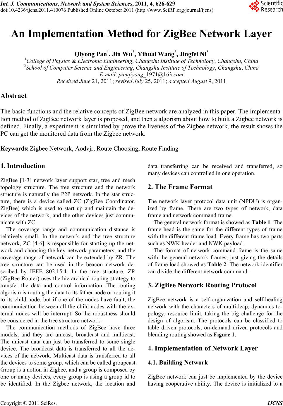 Int. J. Communications, Network and System Sciences, 2011, 4, 626-629 doi:10.4236/ijcns.2011.410076 Published Online October 2011 (http://www.SciRP.org/journal/ijcns) Copyright © 2011 SciRes. IJCNS An Implementation Method for ZigBee Network Layer Qiyong Pan1, Jin Wu2, Yihuai Wang2, Jingfei Ni2 1College of Physics & Electronic Engineering, Changshu Institute of Technology, Changshu, China 2School of Computer Science and Engineering, Changshu Institute of Technology, Changshu, China E-mail: panqiyong_1971@163.com Received June 21, 2011; revised July 25, 2011; accepted August 9, 2011 Abstract The basic functions and the relative concepts of ZigBee network are analyzed in this paper. The implementa- tion method of ZigBee network layer is proposed, and then a algorism about how to built a Zigbee network is defined. Finally, a experiment is simulated by prove the liveness of the Zigbee network, the result shows the PC can get the monitored data from the Zigbee network. Keywords: Zigbee Network, Aodvjr, Route Choosing, Route Finding 1. Introduction ZigBee [1-3] network layer support star, tree and mesh topology structure. The tree structure and the network structure is naturally the P2P network. In the star struc- ture, there is a device called ZC (ZigBee Coordinator, ZigBee) which is used to start up and maintain the de- vices of the network, and the other devices just commu- nicate with ZC. The coverage range and communication distance is relatively small. In the network and the tree structure network, ZC [4-6] is responsible for starting up the net- work and choosing the key network parameters, and the coverage range of network can be extended by ZR. The tree structure can be used in the beacon network de- scribed by IEEE 802.15.4. In the tree structure, ZR (ZigBee Router) uses the hierarchical routing strategy to transfer the data and control information. The routing algorism is routing the data to its father node or routing it to its child node, but if one of the nodes have fault, the communication between all the child nodes with the ex- ternal nodes will be interrupt. So the robustness should be considered in the tree structure network. The communication methods of ZigBee have three models, and they are unicast, broadcast and multicast. The unicast data can just be transferred to some single device. The broadcast data is transferred to all the de- vices of the network. Multicast data is transferred to all the devices to some group, which can be called groupcast. Group is a notion in Zigbee, and a group is composed by one or many devices, every group is using a group id to be identified. In the Zigbee network, the location and data transferring can be received and transferred, so many devices can controlled in one operation. 2. The Frame Format The network layer protocol data unit (NPDU) is organ- ized by frame. There are two types of network, data frame and network command frame. The general network format is showed as Table 1. The frame head is the same for the different types of frame with the different frame load. Every frame has two parts such as NWK header and NWK payload. The format of network command frame is the same with the general network frames, just giving the details of frame load showed as Table 2. The network identifier can divide the different network command. 3. ZigBee Network Routing Protocol ZigBee network is a self-organization and self-healing network with the characters of multi-leap, dynamics to- pology, resource limit, taking the big challenge for the design of algorism. The protocols can be classified to table driven protocols, on-demand driven protocols and blending routing showed as Figure 1. 4. Implementation of Network Layer 4.1. Building Network ZigBee network can just be implemented by the device having cooperative ability. The device is initialized to a 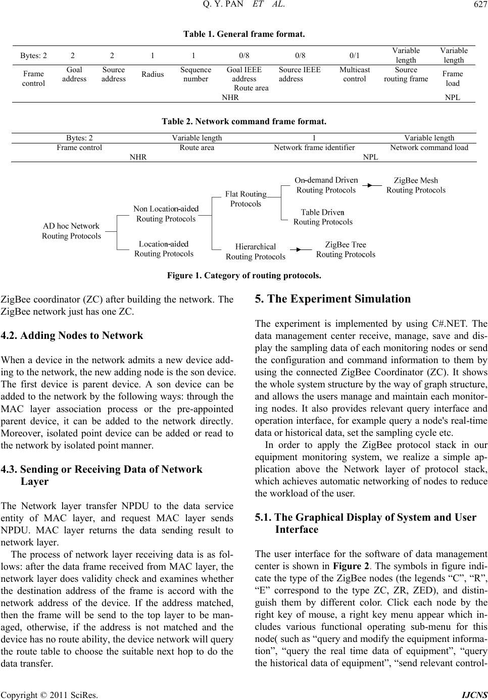 Q. Y. PAN ET AL. 627 Table 1. General frame format. Bytes: 2 2 2 1 1 0/8 0/8 0/1 Variable length Variable length Goal address Source address Radius Sequence number Goal IEEE address Source IEEE address Multicast control Source routing frame Frame control Route area Frame load NHR NPL Table 2. Network co mmand frame format. Bytes: 2 Variable length 1 Variable length Frame control Route area Network frame identifier Network command load NHR NPL Figure 1. Category of routing protocols. ZigBee coordinator (ZC) after building the network. The ZigBee network just has one ZC. 4.2. Adding Nodes to Network When a device in the network admits a new device add- ing to the network, the new adding node is the son device. The first device is parent device. A son device can be added to the network by the following ways: through the MAC layer association process or the pre-appointed parent device, it can be added to the network directly. Moreover, isolated point device can be added or read to the network by isolated point manner. 4.3. Sending or Receiving Data of Network Layer The Network layer transfer NPDU to the data service entity of MAC layer, and request MAC layer sends NPDU. MAC layer returns the data sending result to network layer. The process of network layer receiving data is as fol- lows: after the data frame received from MAC layer, the network layer does validity check and examines whether the destination address of the frame is accord with the network address of the device. If the address matched, then the frame will be send to the top layer to be man- aged, otherwise, if the address is not matched and the device has no route ability, the device network will query the route table to choose the suitable next hop to do the data transfer. 5. The Experiment Simulation The experiment is implemented by using C#.NET. The data management center receive, manage, save and dis- play the sampling data of each monitoring nodes or send the configuration and command information to them by using the connected ZigBee Coordinator (ZC). It shows the whole system structure by the way of graph structure, and allows the users manage and maintain each monitor- ing nodes. It also provides relevant query interface and operation interface, for example query a node's real-time data or historical data, set the sampling cycle etc. In order to apply the ZigBee protocol stack in our equipment monitoring system, we realize a simple ap- plication above the Network layer of protocol stack, which achieves automatic networking of nodes to reduce the workload of the user. 5.1. The Graphical Display of System and User Interface The user interface for the software of data management center is shown in Figure 2. The symbols in figure indi- cate the type of the ZigBee nodes (the legends “C”, “R”, “E” correspond to the type ZC, ZR, ZED), and distin- guish them by different color. Click each node by the right key of mouse, a right key menu appear which in- cludes various functional operating sub-menu for this node( such as “query and modify the equipment informa- tion”, “query the real time data of equipment”, “query the historical data of equipment”, “send relevant control- C opyright © 2011 SciRes. IJCNS 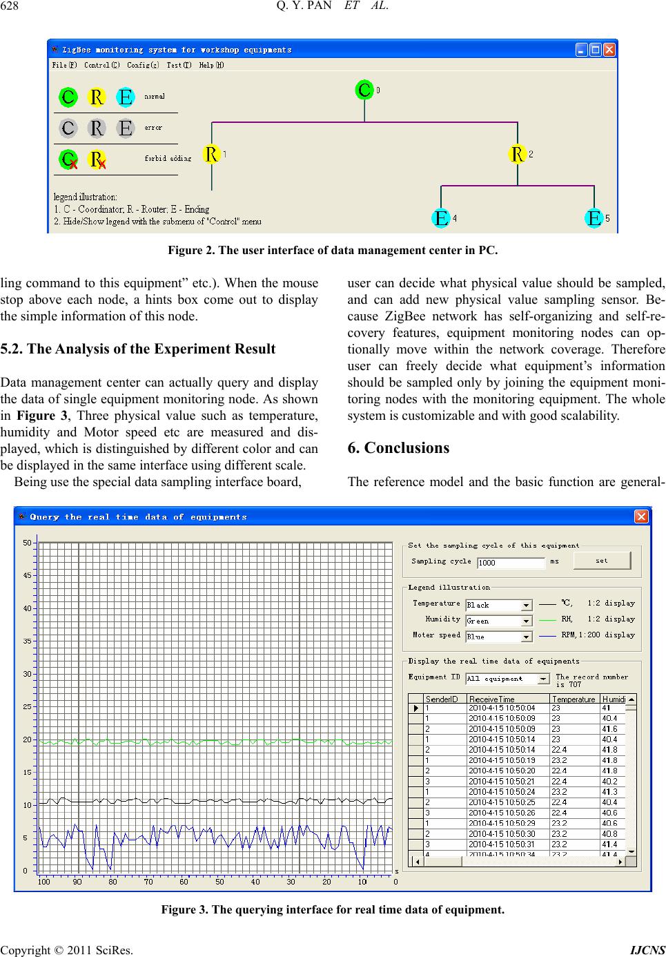 Q. Y. PAN ET AL. 628 Figure 2. The user interface of data management center in PC. ling command to this equipment” etc.). When the mouse stop above each node, a hints box come out to display the simple information of this node. 5.2. The Analysis of the Experiment Result Data management center can actually query and display the data of single equipment monitoring node. As shown in Figure 3, Three physical value such as temperature, humidity and Motor speed etc are measured and dis- played, which is distinguished by different color and can be displayed in the same interface using different scale. Being use the special data sampling interface board, user can decide what physical value should be sampled, and can add new physical value sampling sensor. Be- cause ZigBee network has self-organizing and self-re- covery features, equipment monitoring nodes can op- tionally move within the network coverage. Therefore user can freely decide what equipment’s information should be sampled only by joining the equipment moni- toring nodes with the monitoring equipment. The whole system is customizable and with good scalability. 6. Conclusions The reference model and the basic function are general- Figure 3. The querying interface for real time data of equipment. C opyright © 2011 SciRes. IJCNS 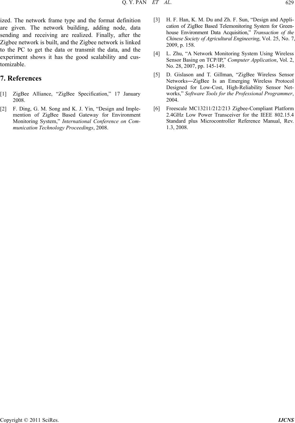 Q. Y. PAN ET AL. 629 ized. The network frame type and the format definition are given. The network building, adding node, data sending and receiving are realized. Finally, after the Zigbee network is built, and the Zigbee network is linked to the PC to get the data or transmit the data, and the experiment shows it has the good scalability and cus- tomizable. 7. References [1] ZigBee Alliance, “ZigBee Specification,” 17 January 2008. [2] F. Ding, G. M. Song and K. J. Yin, “Design and Imple- mention of ZigBee Based Gateway for Environment Monitoring System,” International Conference on Com- munication Technology Proceedings, 2008. [3] H. F. Han, K. M. Du and Zh. F. Sun, “Design and Appli- cation of ZigBee Based Telemonitoring System for Green- house Environment Data Acquisition,” Transaction of the Chinese Society of Agricultural Enginee ring, Vol. 25, No. 7, 2009, p. 158. [4] L. Zhu, “A Network Monitoring System Using Wireless Sensor Basing on TCP/IP,” Computer Application, Vol. 2, No. 28, 2007, pp. 145-149. [5] D. Gislason and T. Gillman, “ZigBee Wireless Sensor Networks―ZigBee Is an Emerging Wireless Protocol Designed for Low-Cost, High-Reliability Sensor Net- works,” Software Tools for the Professional Programmer , 2004. [6] Freescale MC13211/212/213 Zigbee-Compliant Platform 2.4GHz Low Power Transceiver for the IEEE 802.15.4 Standard plus Microcontroller Reference Manual, Rev. 1.3, 2008. C opyright © 2011 SciRes. IJCNS |