Paper Menu >>
Journal Menu >>
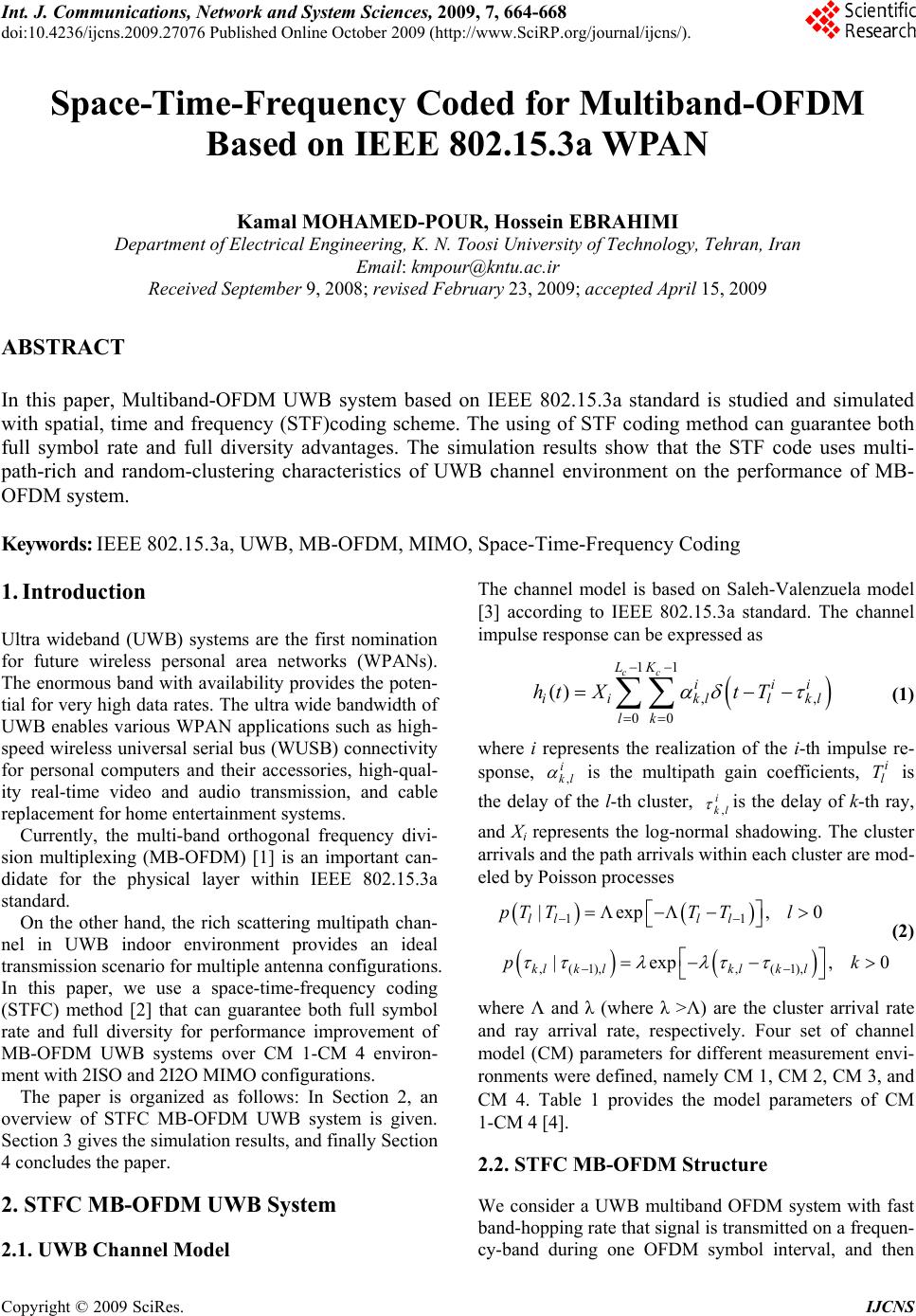 Int. J. Communications, Network and System Sciences, 2009, 7, 664-668 doi:10.4236/ijcns.2009.27076 Published Online October 2009 (http://www.SciRP.org/journal/ijcns/). Copyright © 2009 SciRes. IJCNS Space-Time-Frequency Coded for Multiband-OFDM Based on IEEE 802.15.3a WPAN Kamal MOHAMED-POUR, Hossein EBRAHIMI Department of Electrical Engineering, K. N. Toosi University of Technology, Tehran, Iran Email: kmpour@kntu.ac.ir Received September 9, 2008; revised February 23, 2009; accepted April 15, 2009 ABSTRACT In this paper, Multiband-OFDM UWB system based on IEEE 802.15.3a standard is studied and simulated with spatial, time and frequency (STF)coding scheme. The using of STF coding method can guarantee both full symbol rate and full diversity advantages. The simulation results show that the STF code uses multi- path-rich and random-clustering characteristics of UWB channel environment on the performance of MB- OFDM system. Keywords: IEEE 802.15.3a, UWB, MB-OFDM, MIMO, Space-Time-Frequency Coding 1. Introduction Ultra wideband (UWB) systems are the first nomination for future wireless personal area networks (WPANs). The enormous band with availability provides the poten- tial for very high data rates. The ultra wide bandwidth of UWB enables various WPAN applications such as high- speed wireless universal serial bus (WUSB) connectivity for personal computers and their accessories, high-qual- ity real-time video and audio transmission, and cable replacement for home entertainment systems. Currently, the multi-band orthogonal frequency divi- sion multiplexing (MB-OFDM) [1] is an important can- didate for the physical layer within IEEE 802.15.3a standard. On the other hand, the rich scattering multipath chan- nel in UWB indoor environment provides an ideal transmission scenario for multiple antenna configurations. In this paper, we use a space-time-frequency coding (STFC) method [2] that can guarantee both full symbol rate and full diversity for performance improvement of MB-OFDM UWB systems over CM 1-CM 4 environ- ment with 2ISO and 2I2O MIMO configurations. The paper is organized as follows: In Section 2, an overview of STFC MB-OFDM UWB system is given. Section 3 gives the simulation results, and finally Section 4 concludes the paper. 2. STFC MB-OFDM UWB System 2.1. UWB Channel Model The channel model is based on Saleh-Valenzuela model [3] according to IEEE 802.15.3a standard. The channel impulse response can be expressed as 11 ,, 00 () cc LK ii ii kllk lk htXt T i l (1) where i represents the realization of the i-th impulse re- sponse, , i kl is the multipath gain coefficients, is the delay of the l-th cluster, i l T , i kl is the delay of k-th ray, and Xi represents the log-normal shadowing. The cluster arrivals and the path arrivals within each cluster are mod- eled by Poisson processes 11 |exp , lll l pT TTTl 0 (2) ,(1),, (1), |exp , klklklk l pk 0 where Λ and λ (where λ >Λ) are the cluster arrival rate and ray arrival rate, respectively. Four set of channel model (CM) parameters for different measurement envi- ronments were defined, namely CM 1, CM 2, CM 3, and CM 4. Table 1 provides the model parameters of CM 1-CM 4 [4]. 2.2. STFC MB-OFDM Structure We consider a UWB multiband OFDM system with fast band-hopping rate that signal is transmitted on a frequen- cy-band during one OFDM symbol interval, and then 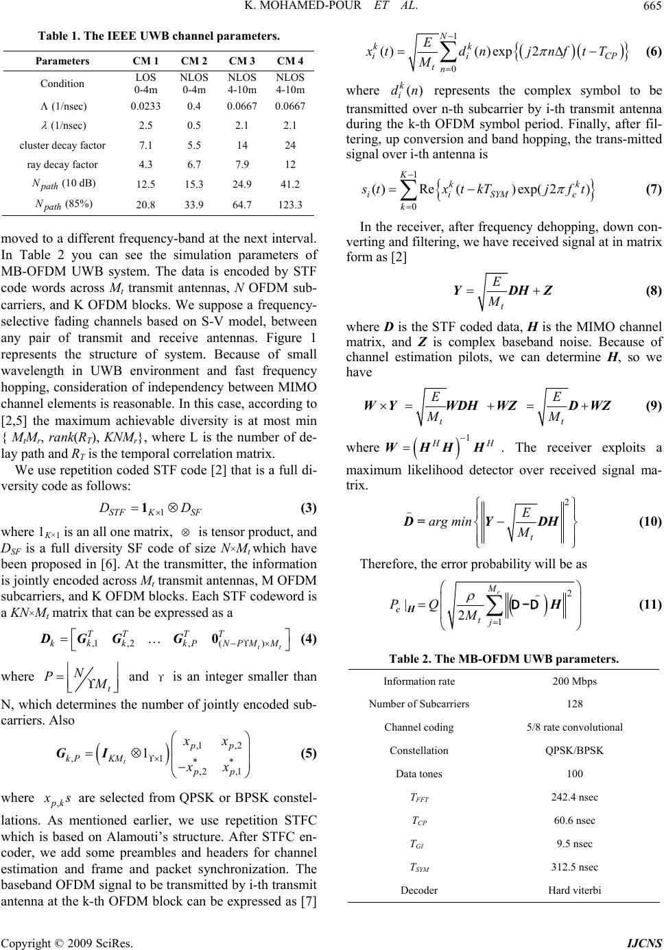 K. MOHAMED-POUR ET AL. 665 Table 1. The IEEE UWB channel parameters. Parameters CM 1 CM 2 CM 3 CM 4 Condition LOS 0-4m NLOS 0-4m NLOS 4-10m NLOS 4-10m (1/nsec) 0.0233 0.4 0.0667 0.0667 (1/nsec) 2.5 0.5 2.1 2.1 cluster decay factor 7.1 5.5 14 24 ray decay factor 4.3 6.7 7.9 12 path N(10 dB) 12.5 15.3 24.9 41.2 path N(85%) 20.8 33.9 64.7 123.3 moved to a different frequency-band at the next interval. In Table 2 you can see the simulation parameters of MB-OFDM UWB system. The data is encoded by STF code words across Mt transmit antennas, N OFDM sub- carriers, and K OFDM blocks. We suppose a frequency- selective fading channels based on S-V model, between any pair of transmit and receive antennas. Figure 1 represents the structure of system. Because of small wavelength in UWB environment and fast frequency hopping, consideration of independency between MIMO channel elements is reasonable. In this case, according to [2,5] the maximum achievable diversity is at most min { MtMr, rank(RT), KNMr}, where L is the number of de- lay path and RT is the temporal correlation matrix. We use repetition coded STF code [2] that is a full di- versity code as follows: 1STF KSF D 1D (3) where 1K×1 is an all one matrix, is tensor product, and DSF is a full diversity SF code of size N×Mt which have been proposed in [6]. At the transmitter, the information is jointly encoded across Mt transmit antennas, M OFDM subcarriers, and K OFDM blocks. Each STF codeword is a KN×Mt matrix that can be expressed as a ,1 ,2, () tt TT TT kkk kPNPMM 0DGGG (4) where t N P M and is an integer smaller than N, which determines the number of jointly encoded sub- carriers. Also ,1 ,2 ,1 ** ,2 ,1 1 t pp kP KM pp xx xx GI (5) where ,pk x s are selected from QPSK or BPSK constel- lations. As mentioned earlier, we use repetition STFC which is based on Alamouti’s structure. After STFC en- coder, we add some preambles and headers for channel estimation and frame and packet synchronization. The baseband OFDM signal to be transmitted by i-th transmit antenna at the k-th OFDM block can be expressed as [7] 1 0 ()( )exp2 N kk ii tn E xtdnjnf tT M CP c (6) where represents the complex symbol to be transmitted over n-th subcarrier by i-th transmit antenna during the k-th OFDM symbol period. Finally, after fil- tering, up conversion and band hopping, the trans-mitted signal over i-th antenna is () k i dn 1 0 ()Re()exp( 2) Kkk iiSYM k s txtkTjf t (7) In the receiver, after frequency dehopping, down con- verting and filtering, we have received signal at in matrix form as [2] t E M YDHZ (8) where D is the STF coded data, H is the MIMO channel matrix, and Z is complex baseband noise. Because of channel estimation pilots, we can determine H, so we have tt EE MM WYWDHWZDWZ (9) where 1 H H WHHH . The receiver exploits a maximum likelihood detector over received signal ma- trix. 2 t E arg min M D=YDH (10) Therefore, the error probability will be as 2 1 |2 r M etj PQ M HH (11) Table 2. The MB-OFDM UWB parameters. Information rate 200 Mbps Number of Subcarriers 128 Channel coding 5/8 rate convolutional Constellation QPSK/BPSK Data tones 100 TFFT 242.4 nsec TCP 60.6 nsec TGI 9.5 nsec TSYM 312.5 nsec Decoder Hard viterbi Copyright © 2009 SciRes. IJCNS  K. MOHAMED-POUR ET AL. Copyright © 2009 SciRes. IJCNS 666 Figure 1. STFC MB-OFDM UWB system. 012345678910 0 0. 05 0. 1 0. 15 0. 2 0. 25 0. 3 0. 35 0. 4 0. 45 Delay (ns) P ower 0 2 46 81012 14161820 0 0.05 0. 1 0.15 0. 2 0.25 0. 3 0.35 0. 4 0.45 0. 5 Dela y (n s ) P ower (a) (b) 05 10 15 20 25 0 0. 05 0. 1 0. 15 0. 2 0. 25 0. 3 0. 35 0. 4 0. 45 0. 5 Del a y ( ns) Powe r 05 10 15 20 25 0 0. 05 0.1 0. 15 0.2 0. 25 0.3 0. 35 0.4 0. 45 0.5 Del a y ( ns) Power (c) (d) Figure 2. Simulated channel response; a) CM 1, b) CM 2, c) CM 3, d) CM 4. 3. Simulation Results We performed simulations for a multiband UWB system with N = 128 subcarriers and the subband bandwidth of 528 MHz. Each OFDM symbol was of duration 242.42 ns. After adding the cyclic prefix of length 60.61 ns and the guard interval of length 9.47 ns, the symbol duration became 312.5 ns. Figure 2 gives the simulated channel 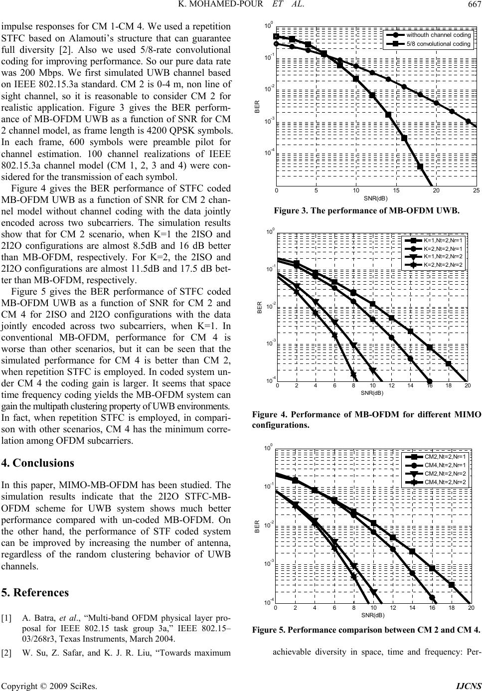 K. MOHAMED-POUR ET AL. 667 impulse responses for CM 1-CM 4. We used a repetition STFC based on Alamouti’s structure that can guarantee full diversity [2]. Also we used 5/8-rate convolutional coding for improving performance. So our pure data rate was 200 Mbps. We first simulated UWB channel based on IEEE 802.15.3a standard. CM 2 is 0-4 m, non line of sight channel, so it is reasonable to consider CM 2 for realistic application. Figure 3 gives the BER perform- ance of MB-OFDM UWB as a function of SNR for CM 2 channel model, as frame length is 4200 QPSK symbols. In each frame, 600 symbols were preamble pilot for channel estimation. 100 channel realizations of IEEE 802.15.3a channel model (CM 1, 2, 3 and 4) were con- sidered for the transmission of each symbol. Figure 4 gives the BER performance of STFC coded MB-OFDM UWB as a function of SNR for CM 2 chan- nel model without channel coding with the data jointly encoded across two subcarriers. The simulation results show that for CM 2 scenario, when K=1 the 2ISO and 2I2O configurations are almost 8.5dB and 16 dB better than MB-OFDM, respectively. For K=2, the 2ISO and 2I2O configurations are almost 11.5dB and 17.5 dB bet- ter than MB-OFDM, respectively. Figure 5 gives the BER performance of STFC coded MB-OFDM UWB as a function of SNR for CM 2 and CM 4 for 2ISO and 2I2O configurations with the data jointly encoded across two subcarriers, when K=1. In conventional MB-OFDM, performance for CM 4 is worse than other scenarios, but it can be seen that the simulated performance for CM 4 is better than CM 2, when repetition STFC is employed. In coded system un- der CM 4 the coding gain is larger. It seems that space time frequency coding yields the MB-OFDM system can gain the multipath clustering property of UWB environments. In fact, when repetition STFC is employed, in compari- son with other scenarios, CM 4 has the minimum corre- lation among OFDM subcarriers. 4. Conclusions In this paper, MIMO-MB-OFDM has been studied. The simulation results indicate that the 2I2O STFC-MB- OFDM scheme for UWB system shows much better performance compared with un-coded MB-OFDM. On the other hand, the performance of STF coded system can be improved by increasing the number of antenna, regardless of the random clustering behavior of UWB channels. 5. References [1] A. Batra, et al., “Multi-band OFDM physical layer pro- posal for IEEE 802.15 task group 3a,” IEEE 802.15– 03/268r3, Texas Instruments, March 2004. [2] W. Su, Z. Safar, and K. J. R. Liu, “Towards maximum 05 1015 20 25 10 -4 10 -3 10 -2 10 -1 10 0 SNR(dB) BER wit houth channel codi ng 5/8 convol uti onal codi ng Figure 3. The performance of MB-OFDM UWB. 02 4 6 810 12 1416 1820 10 -4 10 -3 10 -2 10 -1 10 0 SNR(d B) BER K=1,Nt=2,Nr=1 K=2,Nt=2,Nr=1 K=1,Nt=2,Nr=2 K=2,Nt=2,Nr=2 Figure 4. Performance of MB-OFDM for different MIMO configurations. 02 46 810 12 1416 1820 10 -4 10 -3 10 -2 10 -1 10 0 SNR(dB) BER CM2 ,Nt=2,Nr=1 CM4 ,Nt=2,Nr=1 CM2 ,Nt=2,Nr=2 CM4 ,Nt=2,Nr=2 Figure 5. Performance comparison between CM 2 and CM 4. achievable diversity in space, time and frequency: Per- Copyright © 2009 SciRes. IJCNS  K. MOHAMED-POUR ET AL. Copyright © 2009 SciRes. IJCNS 668 formance analysis and code design,” IEEE Trans. on Wireless Commun., Vol. 4, No. 4, pp. 1847–1857, Jul. 2005. [3] IEEE 802.15WPAN High Rate Alternative PHY Task Group 3a (TG3a). Internet: www.ieee802.org/15/pub/ TG3a.html [4] M. Ghavami, L. B. Michael, and R. Kohno, “Ultra wide- band signals and systems in communication engineering,” John Wiley & Sons, Ltd, 2004. [5] B. Lu, X. Wang, and K. R. Narayanan, “LDPC-based space-time coded OFDM systems over correlated fading channels: Performance analysis and receiver design,” IEEE Trans. Commun., Vol. 50, No. 1, pp. 74–88, Jan. 2002. [6] W. Su, Z. Safar, M. Olfat, and K. J. R. Liu, “Obtaining full-diversity space-frequency codes from space-time codes via mapping,” IEEE Trans. Signal Processing, Vol. 51, pp. 2905–2916, Nov. 2003. [7] W. P. Siriwongpairat, et al, “ Multiband-OFDM MIMO coding framework for UWB communication systems,” IEEE Trans. Signal Processing, Vol. 54, No. 1, Jan. 2006. |