Paper Menu >>
Journal Menu >>
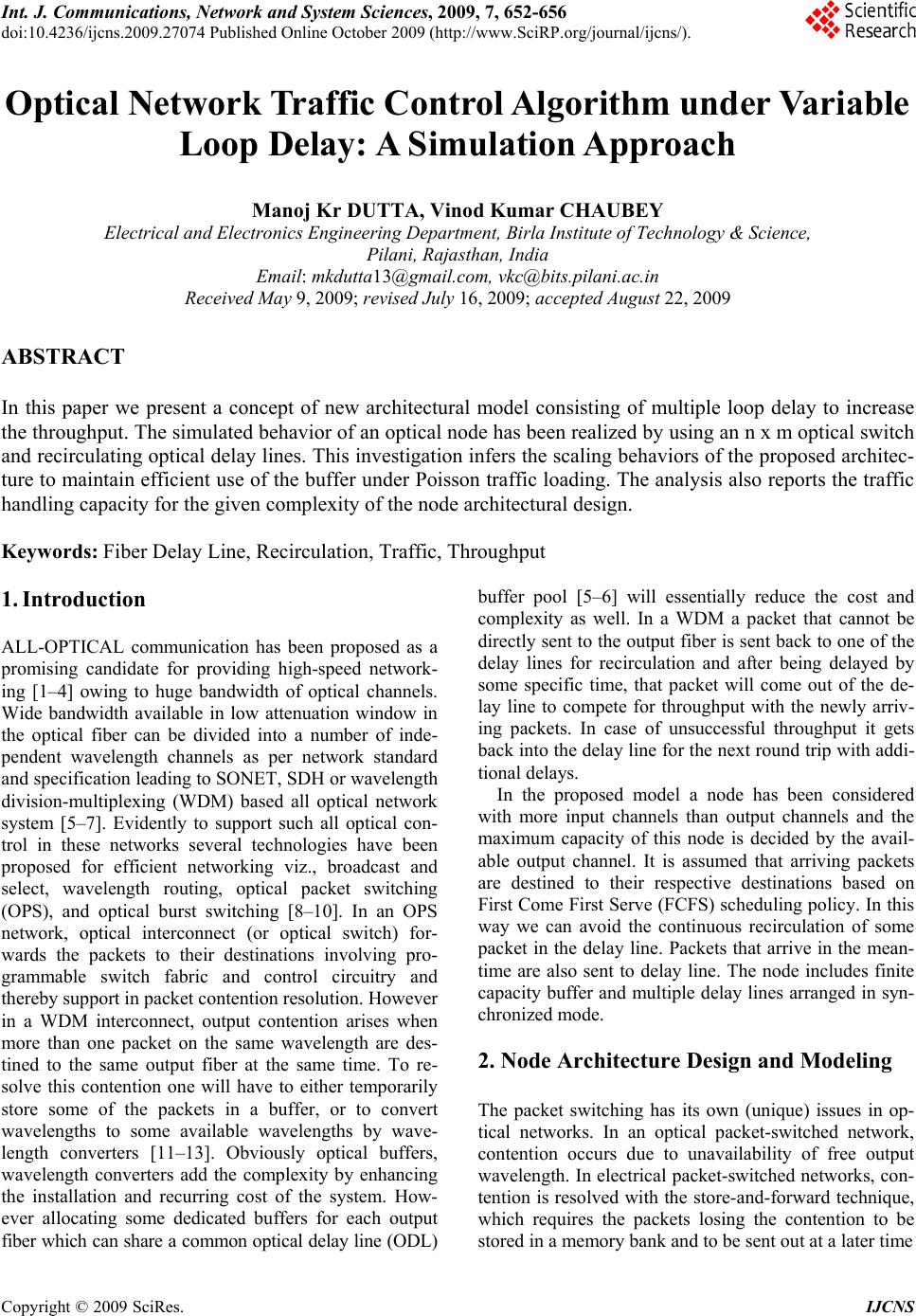
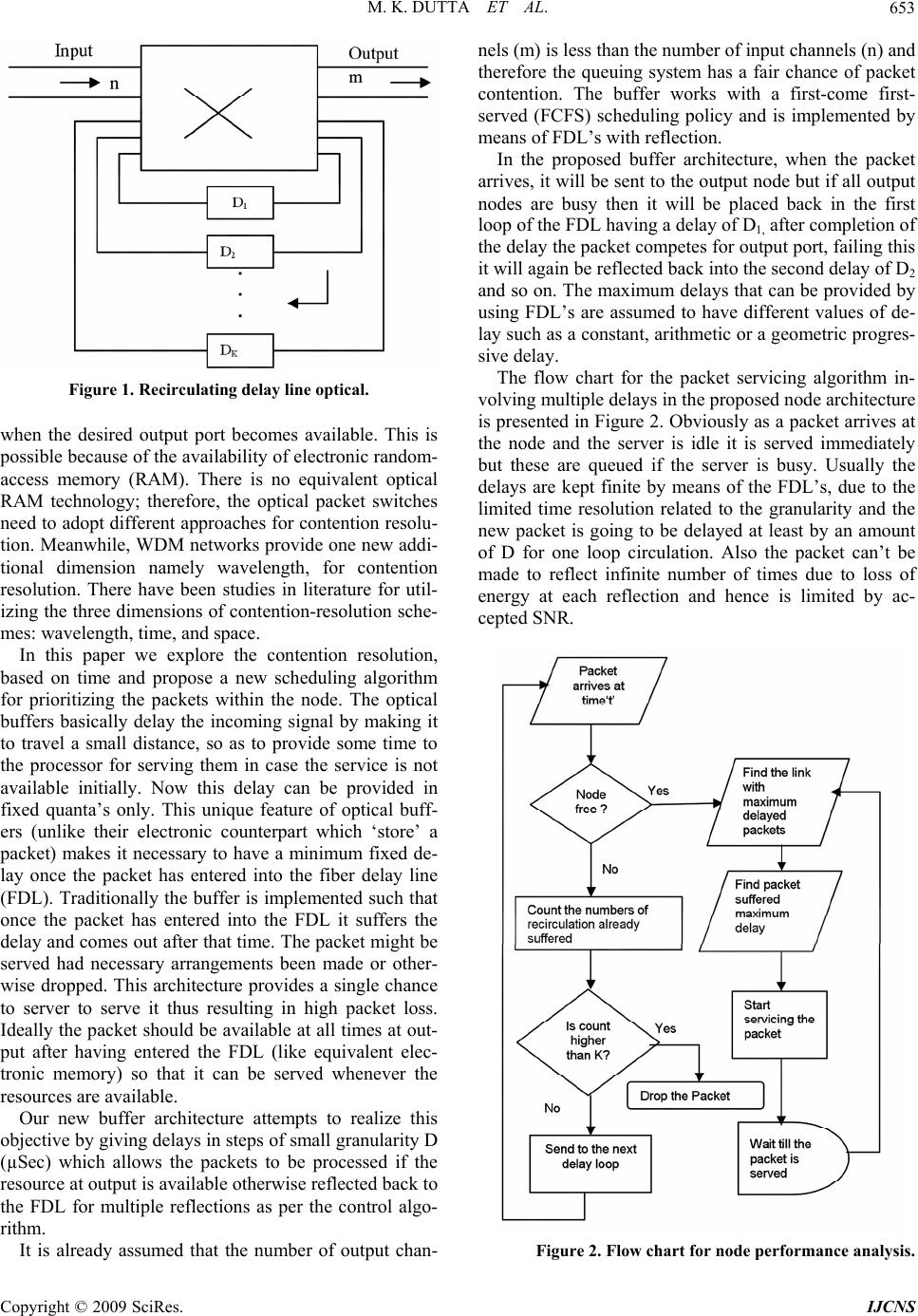
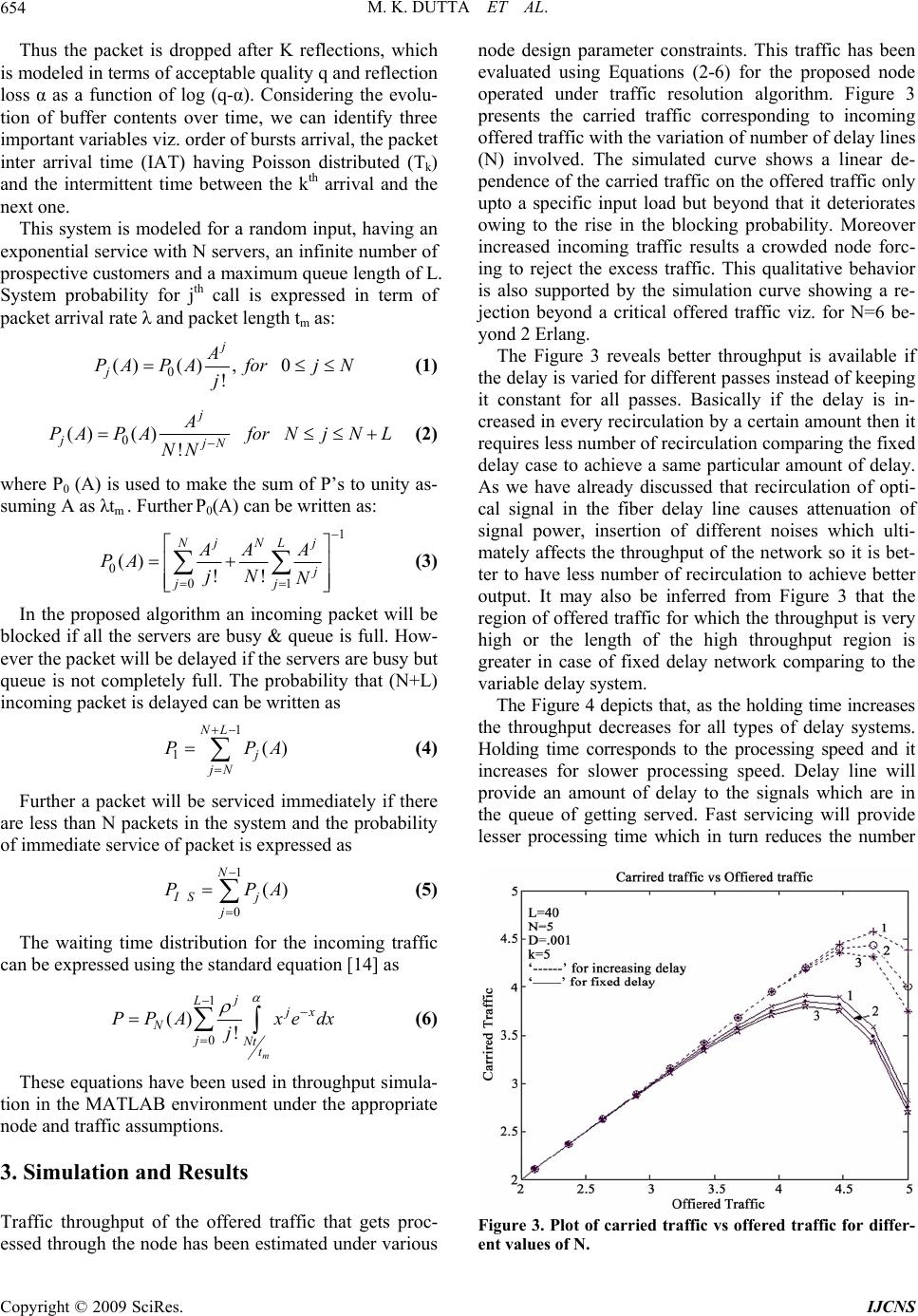
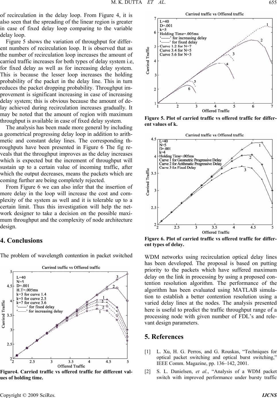
 Int. J. Communications, Network and System Sciences, 2009, 7, 652-656 doi:10.4236/ijcns.2009.27074 Published Online October 2009 (http://www.SciRP.org/journal/ijcns/). Copyright © 2009 SciRes. IJCNS Optical Network Traffic Control Algorithm under Variable Loop Delay: A Simulation Approach Manoj Kr DUTTA, Vinod Kumar CHAUBEY Electrical and Electronics Engineering Department, Birla Institute of Technology & Science, Pilani, Rajasthan, India Email: mkdutta13@gmail.com, vkc@bits.pilani.ac.in Received May 9, 2009; revised July 16, 2009; accepted August 22, 2009 ABSTRACT In this paper we present a concept of new architectural model consisting of multiple loop delay to increase the throughput. The simulated behavior of an optical node has been realized by using an n x m optical switch and recirculating optical delay lines. This investigation infers the scaling behaviors of the proposed architec- ture to maintain efficient use of the buffer under Poisson traffic loading. The analysis also reports the traffic handling capacity for the given complexity of the node architectural design. Keywords: Fiber Delay Line, Recirculation, Traffic, Throughput 1. Introduction ALL-OPTICAL communication has been proposed as a promising candidate for providing high-speed network- ing [1–4] owing to huge bandwidth of optical channels. Wide bandwidth available in low attenuation window in the optical fiber can be divided into a number of inde- pendent wavelength channels as per network standard and specification leading to SONET, SDH or wavelength division-multiplexing (WDM) based all optical network system [5–7]. Evidently to support such all optical con- trol in these networks several technologies have been proposed for efficient networking viz., broadcast and select, wavelength routing, optical packet switching (OPS), and optical burst switching [8–10]. In an OPS network, optical interconnect (or optical switch) for- wards the packets to their destinations involving pro- grammable switch fabric and control circuitry and thereby support in packet contention resolution. However in a WDM interconnect, output contention arises when more than one packet on the same wavelength are des- tined to the same output fiber at the same time. To re- solve this contention one will have to either temporarily store some of the packets in a buffer, or to convert wavelengths to some available wavelengths by wave- length converters [11–13]. Obviously optical buffers, wavelength converters add the complexity by enhancing the installation and recurring cost of the system. How- ever allocating some dedicated buffers for each output fiber which can share a common optical delay line (ODL) buffer pool [5–6] will essentially reduce the cost and complexity as well. In a WDM a packet that cannot be directly sent to the output fiber is sent back to one of the delay lines for recirculation and after being delayed by some specific time, that packet will come out of the de- lay line to compete for throughput with the newly arriv- ing packets. In case of unsuccessful throughput it gets back into the delay line for the next round trip with addi- tional delays. In the proposed model a node has been considered with more input channels than output channels and the maximum capacity of this node is decided by the avail- able output channel. It is assumed that arriving packets are destined to their respective destinations based on First Come First Serve (FCFS) scheduling policy. In this way we can avoid the continuous recirculation of some packet in the delay line. Packets that arrive in the mean- time are also sent to delay line. The node includes finite capacity buffer and multiple delay lines arranged in syn- chronized mode. 2. Node Architecture Design and Modeling The packet switching has its own (unique) issues in op- tical networks. In an optical packet-switched network, contention occurs due to unavailability of free output wavelength. In electrical packet-switched networks, con- tention is resolved with the store-and-forward technique, which requires the packets losing the contention to be stored in a memory bank and to be sent out at a later time  M. K. DUTTA ET AL. 653 Figure 1. Recirculating delay line optical. when the desired output port becomes available. This is possible because of the availability of electronic random- access memory (RAM). There is no equivalent optical RAM technology; therefore, the optical packet switches need to adopt different approaches for contention resolu- tion. Meanwhile, WDM networks provide one new addi- tional dimension namely wavelength, for contention resolution. There have been studies in literature for util- izing the three dimensions of contention-resolution sche- mes: wavelength, time, and space. In this paper we explore the contention resolution, based on time and propose a new scheduling algorithm for prioritizing the packets within the node. The optical buffers basically delay the incoming signal by making it to travel a small distance, so as to provide some time to the processor for serving them in case the service is not available initially. Now this delay can be provided in fixed quanta’s only. This unique feature of optical buff- ers (unlike their electronic counterpart which ‘store’ a packet) makes it necessary to have a minimum fixed de- lay once the packet has entered into the fiber delay line (FDL). Traditionally the buffer is implemented such that once the packet has entered into the FDL it suffers the delay and comes out after that time. The packet might be served had necessary arrangements been made or other- wise dropped. This architecture provides a single chance to server to serve it thus resulting in high packet loss. Ideally the packet should be available at all times at out- put after having entered the FDL (like equivalent elec- tronic memory) so that it can be served whenever the resources are available. Our new buffer architecture attempts to realize this objective by giving delays in steps of small granularity D (µSec) which allows the packets to be processed if the resource at output is available otherwise reflected back to the FDL for multiple reflections as per the control algo- rithm. It is already assumed that the number of output chan- nels (m) is less than the number of input channels (n) and therefore the queuing system has a fair chance of packet contention. The buffer works with a first-come first- served (FCFS) scheduling policy and is implemented by means of FDL’s with reflection. In the proposed buffer architecture, when the packet arrives, it will be sent to the output node but if all output nodes are busy then it will be placed back in the first loop of the FDL having a delay of D1, after completion of the delay the packet competes for output port, failing this it will again be reflected back into the second delay of D2 and so on. The maximum delays that can be provided by using FDL’s are assumed to have different values of de- lay such as a constant, arithmetic or a geometric progres- sive delay. The flow chart for the packet servicing algorithm in- volving multiple delays in the proposed node architecture is presented in Figure 2. Obviously as a packet arrives at the node and the server is idle it is served immediately but these are queued if the server is busy. Usually the delays are kept finite by means of the FDL’s, due to the limited time resolution related to the granularity and the new packet is going to be delayed at least by an amount of D for one loop circulation. Also the packet can’t be made to reflect infinite number of times due to loss of energy at each reflection and hence is limited by ac- cepted SNR. Figure 2. Flow chart for node performance analysis. Copyright © 2009 SciRes. IJCNS  M. K. DUTTA ET AL. 654 Thus the packet is dropped after K reflections, which is modeled in terms of acceptable quality q and reflection loss α as a function of log (q-α). Considering the evolu- tion of buffer contents over time, we can identify three important variables viz. order of bursts arrival, the packet inter arrival time (IAT) having Poisson distributed (Tk) and the intermittent time between the kth arrival and the next one. This system is modeled for a random input, having an exponential service with N servers, an infinite number of prospective customers and a maximum queue length of L. System probability for jth call is expressed in term of packet arrival rate λ and packet length tm as: 0 ()() ,0 ! j jA PAPAforj N j (1) 0 ()() ! j jjN A PAPAforNjN L NN (2) where P0 (A) is used to make the sum of P’s to unity as- suming A as λtm . Further P0(A) can be written as: 1 0 01 () !! jN j NL j jj AA A PA jN N A A (3 ) In the proposed algorithm an incoming packet will be blocked if all the servers are busy & queue is full. How- ever the packet will be delayed if the servers are busy but queue is not completely full. The probability that (N+L) incoming packet is delayed can be written as 1 1() NL j jN PP (4) Further a packet will be serviced immediately if there are less than N packets in the system and the probability of immediate service of packet is expressed as 1 0 () N IS j j PP (5) The waiting time distribution for the incoming traffic can be expressed using the standard equation [14] as 1 0 () ! m j Ljx NjNtt PPA xedx j (6 ) These equations have been used in throughput simula- tion in the MATLAB environment under the appropriate node and traffic assumptions. 3. Simulation and Results Traffic throughput of the offered traffic that gets proc- essed through the node has been estimated under various node design parameter constraints. This traffic has been evaluated using Equations (2-6) for the proposed node operated under traffic resolution algorithm. Figure 3 presents the carried traffic corresponding to incoming offered traffic with the variation of number of delay lines (N) involved. The simulated curve shows a linear de- pendence of the carried traffic on the offered traffic only upto a specific input load but beyond that it deteriorates owing to the rise in the blocking probability. Moreover increased incoming traffic results a crowded node forc- ing to reject the excess traffic. This qualitative behavior is also supported by the simulation curve showing a re- jection beyond a critical offered traffic viz. for N=6 be- yond 2 Erlang. The Figure 3 reveals better throughput is available if the delay is varied for different passes instead of keeping it constant for all passes. Basically if the delay is in- creased in every recirculation by a certain amount then it requires less number of recirculation comparing the fixed delay case to achieve a same particular amount of delay. As we have already discussed that recirculation of opti- cal signal in the fiber delay line causes attenuation of signal power, insertion of different noises which ulti- mately affects the throughput of the network so it is bet- ter to have less number of recirculation to achieve better output. It may also be inferred from Figure 3 that the region of offered traffic for which the throughput is very high or the length of the high throughput region is greater in case of fixed delay network comparing to the variable delay system. The Figure 4 depicts that, as the holding time increases the throughput decreases for all types of delay systems. Holding time corresponds to the processing speed and it increases for slower processing speed. Delay line will provide an amount of delay to the signals which are in the queue of getting served. Fast servicing will provide lesser processing time which in turn reduces the number Figure 3. Plot of carried traffic vs offered traffic for differ- ent values of N. Copyright © 2009 SciRes. IJCNS  M. K. DUTTA ET AL. 655 of recirculation in the delay loop. From Figure 4, it is also seen that the spreading of the linear region is greater in case of fixed delay loop comparing to the variable delay loop. Figure 5 shows the variation of throughput for differ- ent numbers of recirculation loop. It is observed that as the number of recirculation loop increases the amount of carried traffic increases for both types of delay system i.e, for fixed delay as well as for increasing delay system. This is because the lesser loop increases the holding probability of the packet in the delay line. This in turn reduces the packet dropping probability. Throughput im- provement is significant increasing in case of increasing delay system; this is obvious because the amount of de- lay achieved during recirculation increases gradually. It may be noted that the amount of region with maximum throughput is available in case of fixed delay system. The analysis has been made more general by including a geometrical progressing delay loop in addition to arith- metic and constant delay lines. The corresponding th- roughputs have been presented in Figure 6 The fig re- veals that the throughput improves as the delay increases which is expected but the increment of throughput will sustain up to a certain value of incoming traffic, after which the output decreases, means the packets which are coming further are being completely rejected. From Figure 6 we can also infer that the insertion of more delay in the loop will increase the cost and com- plexity of the system as well and it is tolerable up to a certain limit. Thus this investigation will help the net- work designer to take a decision on the possible maxi- mum throughput and the complexity of node architecture design. 4. Conclusions The problem of wavelength contention in packet switched Figure4. Carried traffic vs offered traffic for different val- ues of holding time. Figure 5. Plot of carried traffic vs offered traffic for differ- ent values of k. Figure 6. Plot of carried traffic vs offered traffic for differ- ent types of delay. WDM networks using recirculation optical delay lines has been developed. The proposal is based on putting priority to the packets which have suffered maximum delay on the link in processing by using a proposed con- tention resolution algorithm. The performance of the algorithm has been evaluated using MATLAB simula- tion to establish a better contention resolution using a varied delay lines at the nodes. The analysis presented here is useful to predict the traffic throughput range of a processing node with given number of FDL’s and rele- vant design parameters. 5. References [1] L. Xu, H. G. Perros, and G. Rouskas, “Techniques for optical packet switching and optical burst switching,” IEEE Comm. Magazine, pp. 136–142, 2001. [2] S. L. Danielsen, et al., “Analysis of a WDM packet switch with improved performance under bursty traffic Copyright © 2009 SciRes. IJCNS  M. K. DUTTA ET AL. Copyright © 2009 SciRes. IJCNS 656 conditions due to tunable wavelength converters,” J. Lightwave Technology, Vol. 16, No. 5, pp. 729–735, 1998. [3] G. Shen, et al., “Performance study on a WDM packet switch with limited-range wavelength converters,” IEEE Comm. Letters, Vol. 5, No. 10, pp. 432–434, 2001. [4] Y. Yang, J. Wang, and C. Qiao, “Nonblocking WDM multicast switching networks,” IEEE Trans. Parallel and Distributed Systems, Vol. 11, No. 12, pp. 1274–1287, Dec. 2000. [5] D. K. Hunter and I. Andronovic, “Approaches to optical internet packet switching,” IEEE Comm. Magazine, Vol. 38, No. 9, pp. 116–122, 2000. [6] C. Develder, M. Pickavet, and P. Demeester, “Assess- ment of packet loss for an optical packet router with re- circulating buffer,” Proc. Conf. Optical Network Design and Modeling, pp. 247–261, 2002. [7] W. Lin , R. S. Wolff and B. Mumey, “A markov-based reservation algorithm for wavelength assignment in all- optical netwrks,” Journal of Lightwave Technology, Vol. 25, No. 7, pp. 1676–1683, July 2007. [8] V. K. Chaubey and K. Divakar, “Modeling and simula- tion of WDM optical networks under traffic control pro- tocols,” Optical Fiber Technology (Elsevier), Vol. 15, pp. 95–99, Jan. 2009. [9] J. Li , C. Qiao, J. Xu and D. Xu, “Maximizing throughput for optical burst switching networks,” IEEE/ACM Tran- sactions on Networking, Vol. 15, Issue 5, pp. 1163–1176, October 2007. [10] R. Kundu, V. K. Chaubey, “Analysis of optical WDM network topologies with application of LRWC under symmetric erlang - C traffic,” Novel Algorithms and Techniques in Telecommunications, Automation and In- dustrial Electronics, pp. 468–473, Aug. 2008. [11] R. Ramamurthy and B. Mukherjee, “Fixed-alternate rout- ing and wavelength conversion in wavelength-routed op- tical networks,” IEEE/ACM Transactions on Network- ing, Vol. 10, No. 3, pp. 351–367, June 2002. [12] Y. Zhou and G. S. Poo, “Multicast wavelength assign- ment for sparse wavelength conversion in WDM net- works,” INFOCOM’06, 25th IEEE International Confer- ence on Computer Communications Proceedings, pp. 1– 10, April 2006. [13] P. RajlakshmiN and A. Jhunjhunwala, “Anlytical tool to achieve wavelength conversion performance in no wave- length conversion optical WDM networks,” IEEE Inter- national Conference on Communications, ICC’07. pp. 2436–2441, 24–28 June 2007. [14] A. O. Allen, “Probability, statistics, and queueing theory with computer science applications,” Academic Press INC, USA, 1990. |

