P. Q. THAI ET AL.135
sponses of the received signal around the non-error signal.
This phenomenon, called “paired echo”, is caused by
dispersion error as studied in [18]. Depending on the
disturbance’s period, the 3 dB width of the main lobe may
increase or new sidelobes may arise in the impulse re-
sponse.
Preliminary study was done in [9]. Further analysis has
shown that the negative effect of GDR is nearly non-
existent. In the hybrid system, only two wavelengths were
tuned across a small region in the grating. Furthermore,
only a part of the total delay was from the grating. As a
result, the influence from GDR was minimized. Although
the echo was presented at several different positions in
time domain, the displacement of them was greatly re-
duced to a few picoseconds, while the LFM pulse duration
is usually in microseconds. Since the scaling is so dis-
tinctive, the negative effects such as distortions from
additive and subtractive combinations are negligible. The
study in [12] also agreed that small ripples do not reduce
the system performance. However, the system in [12]
could not achieve this goal since every element was under
the influence from GDR.
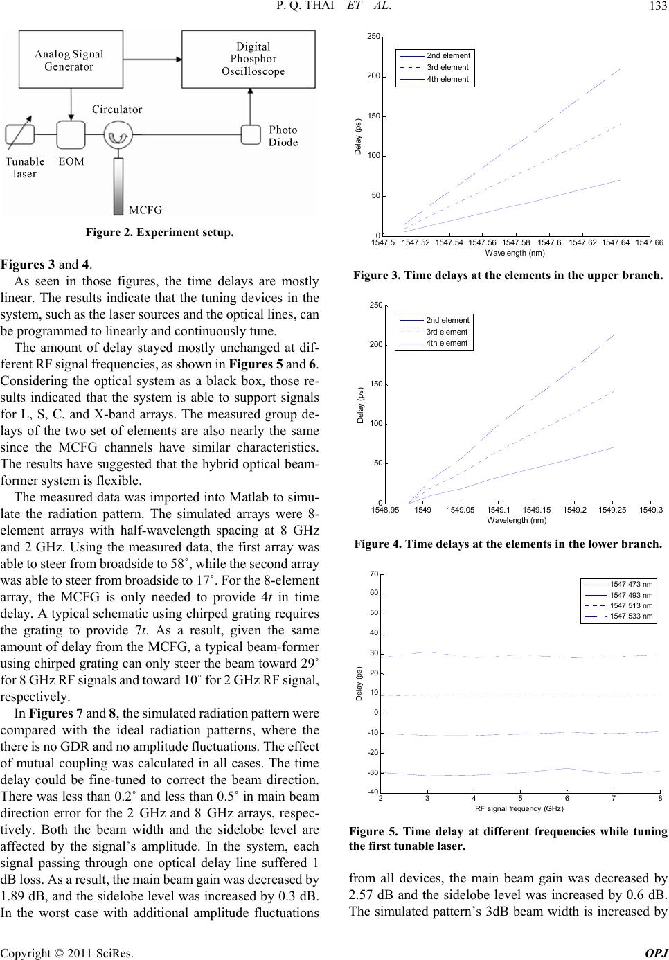
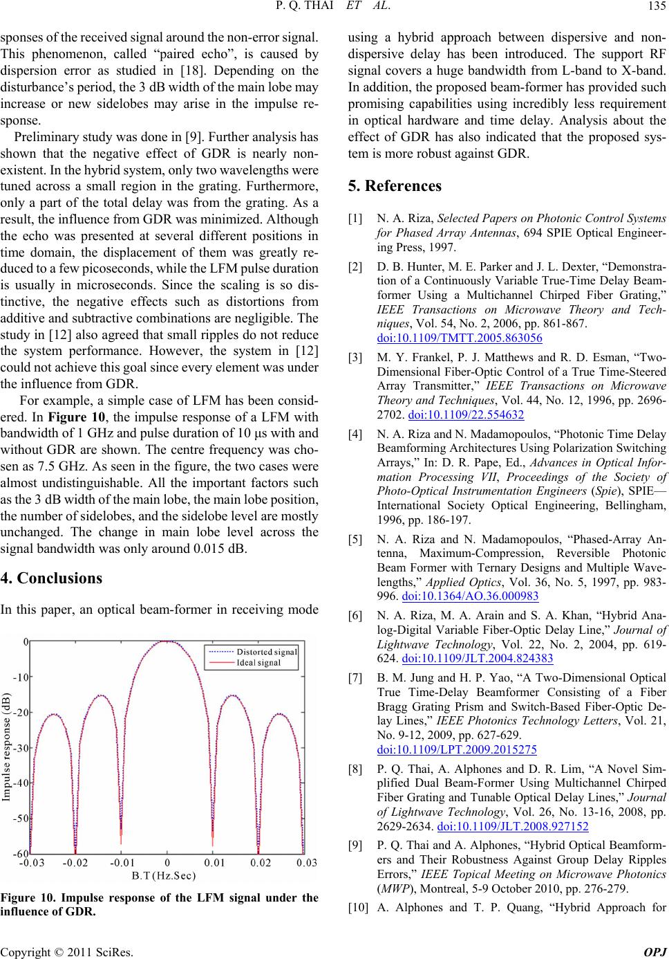
For example, a simple case of LFM has been consid-
ered. In Figure 10, the impulse response of a LFM with
bandwidth of 1 GHz and pulse duration of 10 μs with and
without GDR are shown. The centre frequency was cho-
sen as 7.5 GHz. As seen in the figure, the two cases were
almost undistinguishable. All the important factors such
as the 3 dB width of the main lobe, the main lobe position,
the number of sidelobes, and the sidelobe level are mostly
unchanged. The change in main lobe level across the
signal bandwidth was only around 0.015 dB.
4. Conclusions
In this paper, an optical beam-former in receiving mode
Figure 10. Impulse response of the LFM signal under the
influence of GDR.
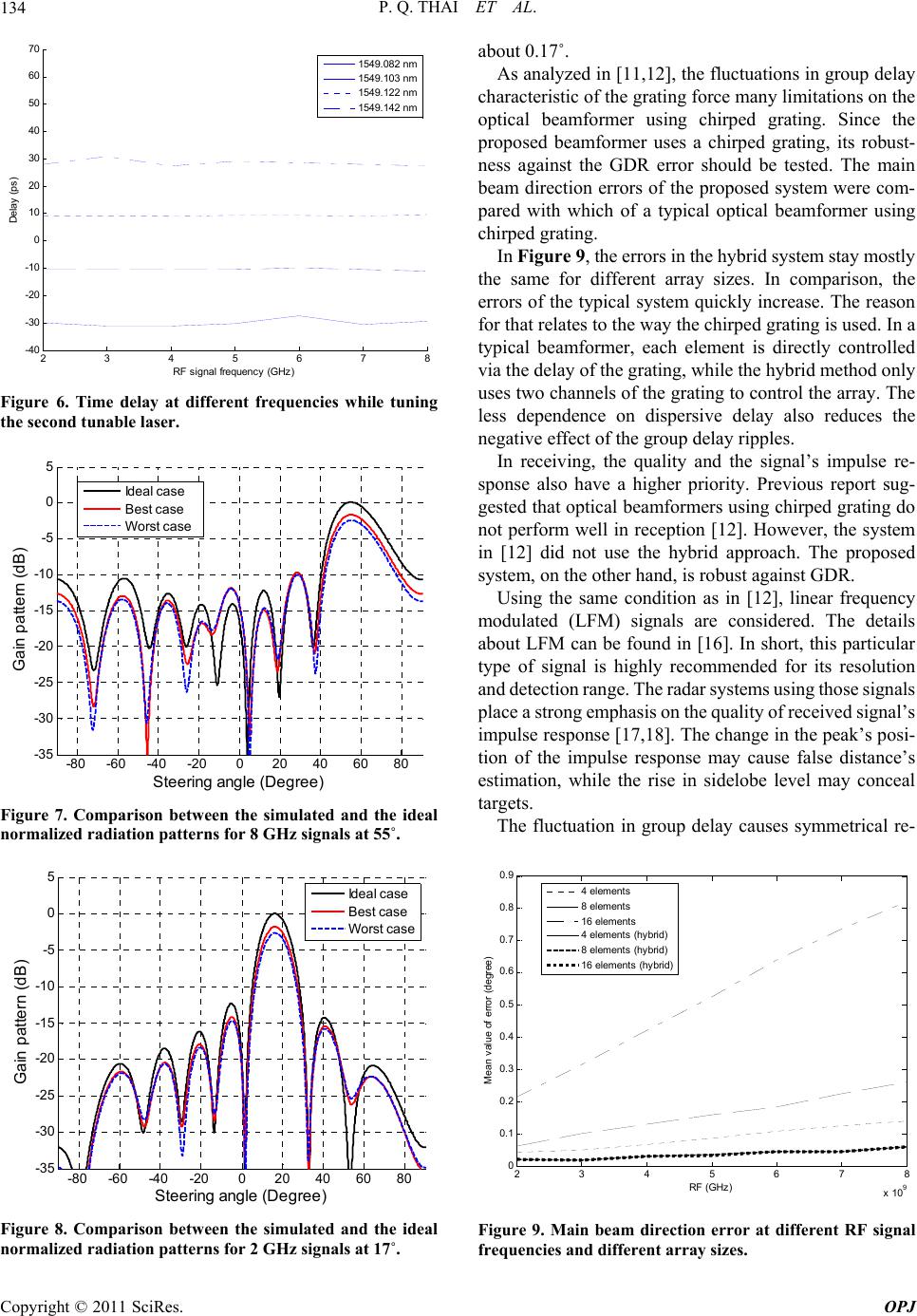
using a hybrid approach between dispersive and non-
dispersive delay has been introduced. The support RF
signal covers a huge bandwidth from L-band to X-band.
In addition, the proposed beam-former has provided such
promising capabilities using incredibly less requirement
in optical hardware and time delay. Analysis about the
effect of GDR has also indicated that the proposed sys-
tem is more robust against GDR.
5. References
[1] N. A. Riza, Selected Papers on Photonic Control Systems
for Phased Array Antennas, 694 SPIE Optical Engineer-
ing Press, 1997.
[2] D. B. Hunter, M. E. Parker and J. L. Dexter, “Demonstra-
tion of a Continuously Variable True-Time Delay Beam-
former Using a Multichannel Chirped Fiber Grating,”
IEEE Transactions on Microwave Theory and Tech-
niques, Vol. 54, No. 2, 2006, pp. 861-867.
doi:10.1109/TMTT.2005.863056
[3] M. Y. Frankel, P. J. Matthews and R. D. Esman, “Two-
Dimensional Fiber-Optic Control of a True Time-Steered
Array Transmitter,” IEEE Transactions on Microwave
Theory and Techniques, Vol. 44, No. 12, 1996, pp. 2696-
2702. doi:10.1109/22.554632
[4] N. A. Riza and N. Madamopoulos, “Photonic Time Delay
Beamforming Architectures Using Polarization Switching
Arrays,” In: D. R. Pape, Ed., Advances in Optical Infor-
mation Processing VII, Proceedings of the Society of
Photo-Optical Instrumentation Engineers (Spie), SPIE—
International Society Optical Engineering, Bellingham,
1996, pp. 186-197.
[5] N. A. Riza and N. Madamopoulos, “Phased-Array An-
tenna, Maximum-Compression, Reversible Photonic
Beam Former with Ternary Designs and Multiple Wave-
lengths,” Applied Optics, Vol. 36, No. 5, 1997, pp. 983-
996. doi:10.1364/AO.36.000983
[6] N. A. Riza, M. A. Arain and S. A. Khan, “Hybrid Ana-
log-Digital Variable Fiber-Optic Delay Line,” Journal of
Lightwave Technology, Vol. 22, No. 2, 2004, pp. 619-
624. doi:10.1109/JLT.2004.824383
[7] B. M. Jung and H. P. Yao, “A Two-Dimensional Optical
True Time-Delay Beamformer Consisting of a Fiber
Bragg Grating Prism and Switch-Based Fiber-Optic De-
lay Lines,” IEEE Photonics Technology Letters, Vol. 21,
No. 9-12, 2009, pp. 627-629.
doi:10.1109/LPT.2009.2015275
[8] P. Q. Thai, A. Alphones and D. R. Lim, “A Novel Sim-
plified Dual Beam-Former Using Multichannel Chirped
Fiber Grating and Tunable Optical Delay Lines,” Journal
of Lightwave Technology, Vol. 26, No. 13-16, 2008, pp.
2629-2634. doi:10.1109/JLT.2008.927152
[9] P. Q. Thai and A. Alphones, “Hybrid Optical Beamform-
ers and Their Robustness Against Group Delay Ripples
Errors,” IEEE Topical Meeting on Microwave Photonics
(MWP), Montreal, 5-9 October 2010, pp. 276-279.
[10] A. Alphones and T. P. Quang, “Hybrid Approach for
Copyright © 2011 SciRes. OPJ