Paper Menu >>
Journal Menu >>
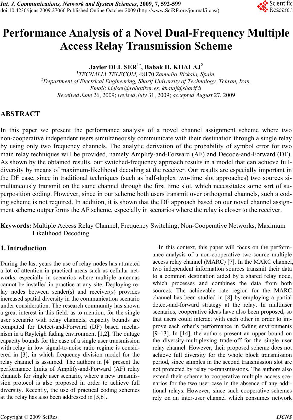 Int. J. Communications, Network and System Sciences, 2009, 7, 592-599 doi:10.4236/ijcns.2009.27066 Published Online October 2009 (http://www.SciRP.org/journal/ijcns/) Copyright © 2009 SciRes. IJCNS Performance Analysis of a Novel Dual-Frequency Multiple Access Relay Transmission Scheme Javier DEL SER1*, Babak H. KHALAJ2 1TECNALIA-TELECOM, 48170 Zamudio-Bizkaia, Spain. 2Department of Electrical Engineering, Sharif University of Technology, Tehran, Iran. Email: jdelser@robotiker.es, khalaj@sharif.ir Received June 26, 2009; revised July 31, 2009; accepted August 27, 2009 ABSTRACT In this paper we present the performance analysis of a novel channel assignment scheme where two non-cooperative independent users simultaneously communicate with their destination through a single relay by using only two frequency channels. The analytic derivation of the probability of symbol error for two main relay techniques will be provided, namely Amplify-and-Forward (AF) and Decode-and-Forward (DF). As shown by the obtained results, our switched-frequency approach results in a model that can achieve full- diversity by means of maximum-likelihood decoding at the receiver. Our results are especially important in the DF case, since in traditional techniques (such as half-duplex two-time slot approaches) two sources si- multaneously transmit on the same channel through the first time slot, which necessitates some sort of su- perposition coding. However, since in our scheme both users transmit over orthogonal channels, such a cod- ing scheme is not required. In addition, it is shown that the DF approach based on our novel channel assign- ment scheme outperforms the AF scheme, especially in scenarios where the relay is closer to the receiver. Keywords: Multiple Access Relay Channel, Frequency Switching, Non-Cooperative Networks, Maximum Likelihood Decoding 1. Introduction During the last years the use of relay nodes has attracted a lot of attention in practical areas such as cellular net- works, especially in scenarios where multiple antennas cannot be installed in practice at any site. Deploying re- lay nodes between sender(s) and receiver(s) provides increased spatial diversity in the communication scenario under consideration. The research community has shown a great interest in this field: as to mention, for the single user scenario with relay channels, capacity bounds are computed for Detect-and-Forward (DF) based mecha- nism in a Rayleigh fading environment [1,2]. The outage capacity bounds for the case of a single user transmission with relay in low signal-to-noise ratio regime is consid- ered in [3], in which frequency division model for the relay channel is assumed. The authors in [4] present the performance limits of Amplify-and-Forward (AF) relay channels for single user scenario, where a new transmis- sion protocol is also proposed in order to achieve full diversity. Recently, the use of practical coding schemes at the relay has also been addressed in [5,6]. In this context, this paper will focus on the perform- ance analysis of a non-cooperative two-source multiple access relay channel (MARC) [7]. In the MARC channel, two independent information sources transmit their data to a common destination aided by a shared relay node, which processes and combines the data from both sources. The achievable rate region for the MARC channel has been studied in [8] by employing a partial detect-and-forward strategy at the relay. In multiuser scenarios, cooperative ideas have also been proposed, so that users could interact with each other in order to im- prove each other’s performance in fading environments [9–13]. In [14], the authors present an upper bound on the diversity-multiplexing trade-off for the single user relay channel. However, their proposed scheme does not achieve full diversity for the whole block transmission period, since samples in the second transmission slot are not protected by relay re-transmissions. The authors also extend their scheme to cooperative multiple access sce- narios for the two user case in the absence of any addi- tional relays. However, since such cooperative schemes rely on an inter-user channel which consumes network  J. DEL SER ET AL. 593 resources and therefore limits their performance by the condition of such a link [15], in this paper we will only focus on non-cooperative multiple access channels. Traditionally, the case of multiple users and a relay has been addressed in a number of different ways. The most straightforward approach is to extend single-relay ideas to multiple users, in which each user uses a sepa- rate frequency and diversity is achieved by utilizing two time-slots. Such an approach is basically an extension of the well-known delay diversity schemes [16,17] and [18], which will naturally lead to a total of four orthogonal time-frequency channels. Another approach is to con- sider independent receive channels for signals coming from the users and the relay, also resulting in a total of four independent channels either in time or frequency. It should be especially noted that, although it is possible to extend half-duplex two-time slot Amplify-and-Forward schemes to MARC scenarios [19], the extension of De- tect-and-Forward schemes to MARC requires the use of complex superposition-type multiuser coding strategies, so that the relay is able to detect multiple sources over the same multiple access channel [8,19,20,21]. The scheme proposed in this paper does not rely on any special coding scheme, since the users transmit to the relay over orthogonal channels. Our analysis will be focused on examining the error performance of the MARC scenario in the case of full multiplexing gain (two independent sources transmitting simultaneously in the same time slot), where diversity gain improvement can be verified through the slope of error probability curve as a function of received SNR in a log-log scale. As will be shown, by using the proposed frequency- switching channel assignment scheme at the relay (Fig- ure 1), the signal model will be transformed from two independent scalar channels into a 2×2 Multiple-Input Multiple-Output (MIMO) model [22]. Consequently, Maximum Likelihood (ML) detection performed over the received vector will provide an overall diversity or- der of two for each user. The structure of the paper is organized as follows. In Section 2, the signal model and the channel assignment scheme will be presented. In addition to Amplify-and- Forward scheme, Detect-and-Forward structure and its corresponding ML detector will be proposed. In Section 3, analytic probability of error computations for both AF and DF schemes will be derived. In Section 4, simulation re- sults for both AF and DF mechanisms for different relay locations will be presented and compared with the analy- sis. As shown in these results, the DF approach outper- forms the AF scheme, especially as the relay gets closer to the destination. Finally, Section 5 concludes the paper. 2. Signal Model In this paper, we will assume the case of two independ- ent and identically distributed (i.i.d.) random sources S1 and S2 which generate binary symbols b1 and b2 (b1, b2∈ {-1,1}), respectively. Those symbols are transmitted in a wireless environment to the same destination. In be- tween these sources and the destination a single dual- frequency relay is located. The distance between sources and destination is normalized to one, and the location of the relay is denoted as d (0<d<1). The channel is as- sumed to be block Rayleigh fading, i.e. the channel is assumed to be fixed within a block and varies independ- ently from block to block. In addition to this Rayleigh model, a propagation loss as a function of distance is considered. This loss is a basic exponential model with exponent n=2, hence the power attenuation is assumed to be equal to K/d2 at a distance d, where K is the propaga- tion constant [23]. The channel state information (CSI) is only assumed to be known at the receiver locations (i.e. both relay and destination), whereas the transmitters are not assumed to have any knowledge of their forward transmission channels. Both users transmit their signals at two different frequency channels f1 and f2, respec- tively. Instead of forwarding each received signal over the same incoming frequency channel, the relay of our pro- posed dual-frequency channel assignment switches the frequencies between the two transmitted signals. The proposed structure is shown in Figure 1, where the source S1 transmits at frequency channel f1, and the relay retransmits the same signal over frequency channel f2. Similarly, the frequency channel of source S2 is switched at the relay before retransmission to the destination. It can be easily verified that, without such frequency switching at the relay, no additional diversity can be achieved without resorting to delay diversity schemes, since the two signals coming from the source and the relay at each frequency are simultaneously combined at the receiver. As will be subsequently shown, the pro- posed channel assignment scheme will transform two independent scalar channels into a two dimensional vec- tor channel which achieves a diversity of order two. Figure 1. The proposed switched frequency assignment at the relay (the number over each link denotes the corresponding frequency c hannel used). Copyright © 2009 SciRes. IJCNS  J. DEL SER ET AL. 594 3 It should be noted that in the proposed scheme, the re- lay should perform in a full-duplex mode for each trans- mission path. In other words, two transceivers should operate simultaneously in the same time slot at the relay. However, since these two transceivers can be stationed separately in hardware and the input carrier frequency of each board is different from its output carrier frequency, the hardware complexity will be significantly less than the traditional full-duplex transceivers that operate on the same carrier frequency for both their input and output signals. In addition, the aforementioned assumption would lead to echo-interference in case of highly asym- metric receive and transmit power. Such an issue could be overcome by applying preprocessing and postproc- essing techniques as done, for instance, in [24]. Never- theless, the echo interference will be assumed to be neg- ligible at the relay, since its suppression falls out of the scope of our contribution. In the next subsections we present the two previously mentioned relaying schemes, DF and AF, particularized for our proposed setup. 2.1. Mplify-and-Forward ML Detector at the Relay Assuming that signals transmitted by each source are denoted by b1 and b2, and that all information symbols from source and relay stations reach the common desti- nation in the same time slot (as done, for instance, in [25, 5]), the received signal for each frequency will be given by Frequency channel f1: 111 25216 = y bhb hnhn (1) Frequency channel f2: 224 12123 =4 y bhbh nh n (2 ) where h1 and h4 denote the channel coefficients between sources S1 and S2 and the destination, h2 and h5 denote channel taps between sources S1 and S2 and the relay, and h3 and h6 denote the channel weights between relay and destination at the two transmit frequencies f1 and f2, cor- respondingly. All channel coefficients are mod- eled as complex Gaussian random variables with zero mean and variance per dimension equal to K/d2 (due to the propagation loss at the distance d). In addition, com- plex circularly symmetric zero mean additive white Gaussian noise are assumed for receive inputs at both relay and destination, with variance per dimension 6 =1 {} ii h 4 =1 {} ii n 20 =2 N . Also, the quantities γ1 andγ2 denote the gain of the relay for each frequency channel f1 and f2, whose values are chosen such that the relay transmits with unit average power. A closer look at the above equations reveals that, by the proposed switching algorithm at the relay, the chan- nel is transformed into a 2×2 MIMO channel model as given by 115611 223 422 16 23 2314 =hhhyb hh hyb hn n hn n 3 (3) As is well-known in MIMO literature, the above model can be solved in the context of standard spatial multiplexing MIMO systems, where the detection based on the Maximum Likelihood (ML) criterion yields a di- versity of order two [26]. Consequently, in our approach we use a ML detector at the destination that will jointly estimate b1 and b2 from the received signals y1 and y2. It should also be observed that in our model, some entries of the channel matrix shown in Equation (3) are multi- plications of Rayleigh variables, and therefore the re- sulting model is not roughly in the conventional form spatial multiplexing models. Nevertheless, the obtained results show that an increased diversity gain of order close to two will still be achieved for both users in the DF approach. 2.2. Detect-and-Forward ML Detector at the Relay Instead of just amplifying and forwarding each signal, in this case the relay detects the source symbol from the received signal before retransmitting it. Consequently, in the DF approach the received signal at destination will be given by Frequency channel f1: 111216 ˆ = y bh b hn (4) Frequency channel f2: 224123 ˆ =4 y bhb hn (5) where and denote the output of the detector at the relay for sources S1 and S2, respectively. 1 ˆ b2 ˆ b It should be noted that in this case, the maximum like- lihood detector at the destination should also consider the effect of detection errors at the output of the relay. Such errors are mainly due to fading events in the source-relay links: when one of these links is affected by a deep fade, the detection errors committed at the relay are propa- gated to the destination. In order to account for both source-relay and relay-destination links, an end-to-end ML detector should be utilized. The associated end-to- end search criterion can be derived by first modeling the source-relay link as a binary symmetric channel (BSC) with probability of error equal to Copyright © 2009 SciRes. IJCNS  J. DEL SER ET AL. 595 12 || = e h PQ (6) 25 || = e h PQ |, (7) where Q(·) denotes the standard Q-function. The esti- mated b1 and b2 values at the final destination, denoted by and , are then computed by maximizing the likelihood function 1 b 2 b 121 212 ,{ 1,1} 12 12 121212 12 ,{1,1} ˆˆ , 12 12 (, )=(,|, ) argmax ˆˆ ˆˆ =(,|,,,)(, argmax bb bb bb bbpy ybb p yybb bbpbbbb (8) where 12 12 12 112 2 12 112 2 12 112 2 12 112 2 ˆˆ (,| ,) ˆˆ (1)(1)= ,=. ˆˆ (1),= . =ˆˆ (1)= ,. ˆˆ ,. ee ee ee ee pb bb b PPifbbbb PP ifbbbb PPifb bbb PPifbb bb (9) It should also be remarked that, since the proposed scheme is working on a single-slot basis, it is assumed that the decoding delay at the relay is negligible with respect to symbol time intervals. Therefore, the relay is able to start the retransmission of the detected symbol after some small delay during the same time slot. 3. Analysis In the following section a detailed derivation of the ana- lytic probability of error for both schemes is provided. We begin by analyzing the AF approach. 3.1. Analysis of Amplify-and-Forward ML Detector at the Relay In order to compute the analytic probability of error for the AF approach, we first rewrite Equation (3) as the sum of a signal term u and a noise term w, i.e. y=u+w, where u is given by 111562 223142 =hbh h b hhbhb u (10) and the noise term w will be zero mean with a covariance expressed as1 1 * 2 0 =0 N N wwE (11) where 2 2 10 16 (1 )NN h and 2 2 20 23 (1 )NN h . Since the two terms of the noise vector w do not present the same variance, we will employ a scaling matrix M so as to transform w into a unit variance vector '= M ww such that * 22 '' = EwwI , yielding 1 2 10 =. (12) 1 0 N M N As previously mentioned, the values of the relay gains γ1 and γ2 are set such that the average relay transmit power is normalized to one, yielding 2 2 25 1 = hh (13) We will henceforth denote the received vector corre- sponding to 12 (, )=(1,1) A bb x by uA. Similarly, vec- tors uB, uC, and uD correspond to , (1,1) B x (1, 1) C x and (1,1) D x, respectively. Assum- ing that the possible transmit vectors (b1,b2) are equiprobable, the total probability of error is thus given by 12 12 12 12 12 = 1 =Pr{error| (,) 4 =}Pr{error|(,) =}Pr{error|(,) =}Pr{error|(,)=} 1 =Pr{error|(,) 4 =}. e A B CD D iA i Pbb bb bb bb bb x x xx x (14) Let us consider the error term corresponding to . Given a set of channel coefficients , we will use the union bound to compute the probability of error when A x 6 1= }{ii h A x was sent, resulting in 6 12 =1 6 =1 6 =1 6 =1 Prerror| (,)=,{} Pr|{ } Pr|{ } Pr|{ } Aii ABii ACii ADii bb h h h h x xx xx xx (15) where 6 =1 Pr|{} ijii hxx denotes the probability that, given a set of channel coefficients , xi is transmit- ted and xj is detected at the receiver. Let us consider the 6 1= }{ ii h term 6 =1 Pr|{} ABii hxx . This pairwise probabil 1 denotes mathematical expectation of a random variable. {}Eity of Copyright © 2009 SciRes. IJCNS  J. DEL SER ET AL. 596 n be obtained by userror caing the transformation in Ex- pression (12), yielding 6 =1 222 2 23 1 12 Pr |{ iji hxx } ||() || =2 |||| || =2 i AB M Q hh h QNN uu (16) where denotes the Frobenius norm. Consequently, other terms in Expressi |||| ionthe un bound for the probability of error 12 Prerror| (,)=A bb x can be computed by adding the on (15) and taking the expectation over channel coefficients hi, i.e. 12 Prerror| (,)=A bb 22 2 2 23 1 12 222 2 56 4 12 22 156 423 12 || || || 2 |||| || 2 ||| | 2 hi hh h QNN hh h QNN hh hh hh QNN E (17) Finally, it can be easily verified that the other terms in Exp x ression (14) can be upper-bounded by a similar ex- pression to that corresponding to 12 Prerror| (,)=A bb x. Therefore, the overall probability by 12 =Prerror| (,)= eA Pbb x, i.e. the same bound givealso be valid for the end-to-end probability of error Pe. As verified by our simulation results, this expression results in a tight up- per-bound of the end-to-end probability of error for the AF approach. .2. Analysis of error will be given n in Equation (17) will of Detect-and-Forward ML qua at the analysis of the DF 3Detector at the Relay tions (4) and (5) show thE method is quite different than that of the AF approach. In the DF case we have complex Gaussian noise of the same variance for both components of the received vec- tor y and, since 1,1}{ ˆ , ˆ21bb, the relay gain factor is set to 2 1, which istion of channel variables. However, the computation of the analytic probability of error for the former is more complicated since the de- tected bit values of 1 ˆ b and 2 ˆ b at the relay are random variables that depend on the condition of the channel from the sources to the relay. In fact, when the vector (1,1)= A x is transmitted from the sources, the noise-free signal uA received at the destination may be any of the g set with the corresponding probability, 16 1 11 ,{= }=(1)(1 not a func followin 2 ) 43 16 12 22 43 16 12 33 43 16 12 44 43 ,{ = }=(1) ,{= }=(1) ,{=}= A Aee hh PrP P hh uuu AA ee AAee AAee hh Pr P P hh hh PrP P hh hh PrPP hh uuu uuu uuu A u where P respectively. Si th (18) and are given in Expressions (6) and (7), larly, if the transmit vector 2 1 e 2 e P mi 1,1)(= B x is sent, e possible received signal set will be 16 1 11 ,{=} =(1)(1 43 16 12 22 43 16 12 33 43 16 12 44 43 ) ,{= }=(1) ,{= }=(1) ,{= }= BB ee BBee BBee P hh PrP P hh hh PrP P hh hh PrP P hh uuu uuu uuu BBe hh Pr P hh uuu e (19) the above definitions, the probability that xA is ted and xB is detected will be then given by the ility of error for the case when xA is sent, i.e. A u From transmit probability that one of the four signals corresponding to xA is transmitted and one of the signals corresponding to xB is detected. Since we have four different transmit pairs (b1,b2) (each of which can be transmitted in four different ways from the relay), an exact computation of the prob- ability of error at the destination will involve complex scenarios of non-uniform vector constellations with non- uniform probabilities. To simplify this computation, we will derive an approximate probability of error by solely accounting for the most probable error events in our scenario. Having said this, we will consider two main terms in the probab 12 error| (,)=A bbPr x. The first component, denoted by ,e P , corresponds to th case that no error has occurred at e the signal uA1 with probability 1 = } AA uu is transmitted among all the points asso- ciated to uA. We will then compute the probability that detected erroneously as one of the three most likely points associated to uB (i.e. ignoring the point uB4 with much smaller probability 4 Pr{ =} BB uu). e , and therefor al is the relay Pr{ this sign Copyright © 2009 SciRes. IJCNS  J. DEL SER ET AL. 597 Consequently, ,e P◇ can be approximated as 22 13 ,1 || || {P }} eA hh PQ 1 2 2 1 22 2* 36 11 6 1 3 22 2* 36 116 2 Pr{=} ln Pr{=} 2| | || ||2() 2 Pr{ =} ln Pr{ =} || || 2|2 () 2 A B A B Q h hh hh h Q hh hhh 2 1 r{ = || || | h uu uu uu uu (20) where for the real part of a complex value, and σ2notesriance per dimension of the noise u stands the va u ◇EE )( de (n3,nterm n=4)T at the destination. Observe that the addi- tional factors 1 2 Pr{=} ln Pr{ =} A B uu uu and 1 3 Pr{=} ln Pr{ =} A B uu uu in the second and tdue to the non-equaon- stellation vectors uA1, uB2 and uB3. The second main component of the proposed ap- proximation for 12 Prerror| (,)bb hird l u 21 || > AB u nt pr jection terms of the above equation are probabilities of occurrence of the c , denoted as 1A (21) The above joiobability can be computed by sidering the pros of the noise term n on the two di =A x es (–1,1) correspondin ,e, is related to the case when the relay has wrongly detected the bit valg to the point Therefore, we must compute the probability that this signal, which belongs to the set associated to XA, is erro- neously detected as XB at destination. In this case, such an error probability can be approximated by the prob- ability that this signal is transmitted by the relay and is detected as the point uB1, which presents the highest probability among all the points associated to uB. In other words, an error event will occur if the received signal y=uA2+n is more likely to be detected as uB1 instead of uA2 or uA1. At this point it should be noted that, since we assume that the signal uA2 is transmitted from the relay, the probability of detecting the less probable constella- tion points uA3 and uA4 is negligible in comparison with the above mentioned probabilities. Thus the second error term ,e P can be approximated by 22 ,21 Pr||()||>|| ()||, eAB P unu unu E P uA2. 2 22 22 || ( )||( )|| A A A un unu con- rections uB1–uA1 and uB1–uA2, and integrating over the joint probability distribution of these two projection terms. Let us denote the correlation factor of these two noise terms as 1211 12 11 2 1 22 2 11 3 , || BABA || |||| 4|| =, 2| |2| ||| BA BA h hh h uuuu uu uu (22) where , denotes the inner product of two vectors. With this definition, Expression (21) reduces to [27] 22 (2 ) 2 2(1 ) 1 xxyy ,2 21 eab Pedxdy E (23) where the integration limits a and b are obtained by computing the distance of the received signal from the decision boundaries between uB1 and uA1 and between uB2 and uA2, respectively. Further geometric manipula- tions lead to 22 1 || |||| ||2< ,> =BA a uu uuu 1211 11 22 222 13 3 22 2 13 2| | || || ||4|| = 2|||| AAB BA hh h hh uu (24) 21 2 21 1 2 12 21 1 ||||{ =} =ln 2|| ||{= || Pr{=} =ln. Pr{=} 2| | AB A AB B A B Pr bPr h h uu uu uu uu uu uu } (25) It should be noted that, when computing , the value ba ,e P◇ obta he r of 2 Pr{=} =(1) Bee PPuu should be ined sed on channel values that cause errors at telay. Analogousl 12 y, ,e P should be computed by averaging over all values of h2 that cause such errors at the relay, and not over thhole range of h2. Finally, the approxi- mate end-to-end probability of error Pe for the DF scheme can be obtained by adding these two main error terms, i.e. ,,ee e PP P ◇ (26) which, as e w shown in next section, i the Monte Carlo simulation results. onte Carlo simulation results r the proposed algorithm in comparison with the pre- s in close match with 4. Simulation Results In this section we provide M fo viously derived analytic approximations. The simulations Copyright © 2009 SciRes. IJCNS  J. DEL SER ET AL. 598 R ratio at tw have been performed assuming BPSK signaling (i.e. b1,b2 ∈{–1,1}). The transmitted signals at the sources and the relay are assumed to be of unit average power. Flat Rayleigh fading coefficients were generated based on a complex Gaussian distribution with variance per 2 di- mensions equal to one. As mentioned earlier, an addi- tional signal power attenuation equal to K/d2 was as- sumed for signal propagation over a distance equal to d, where K is the propagation factor (set to 10–4 in our simulations). Fading coefficients have been assumed to be constant over a block of 100 samples, and are inde- pendently generated over different blocks. The Signal to Noise Ratio (SNR) is defined as the ratio of the average received power of the direct source-destination path of one of the sources (where average transmit power is as- sumed to be equal to one) to the noise variance per di- mension. The noise variance used for computing the SNR has been assumed to be the same at the relay and destination sites. Furthermore, the relay gains γ1 and γ2 have been chosen such that average transmit power of the relay is also normalized to one. Finally, in order to investigate the effect of the relay location on the per- formance of the different considered schemes, the loca- tion of the relay varies over a range of d=0 to d=1. The results for d=0.1 (relay close to sources) and d=0.9 (relay close to destination) are shown in these plots. Figure 2 depicts the probability of symbol error of the proposed DF and AF algorithms versus the SN o different relay locations. First notice that in both approaches the obtained analytic approximation for the probability of error is in close match with the corre- sponding simulated curves. Also observe that the per- formance of the DF approach even improves slightly as the relay position is changed from a location close to sources (d=0.1) to a location close to the destination (d=0.9). However, the performance degrades considera- bly for the AF scheme as the distance between the relay and the sources increases. Based on these results it is foreseen that, in scenarios where the relay is close to the destination, the use of the proposed switched-frequency Figure 2. Analytic and simulated probability of symbol error for the proposed frequency switching AF and DF schemes at two different relay positi ons. ance of a novel commu- ser single-relay multiple art by the Spanish Ministry through the CONSOL- ldsmith, “Capacity and coopera- ,” in Proceedings of Information Theory and Applications (ITA) Workshop, February E Transactions on Information Theory, January on Information Theory, Vol. 53, No. 4, pp. ings of IEEE International Con- on Wireless Ad Hoc and Sensor d turbo equalization in mul DF scheme will yield a significant performance en- hancement (around 10 dB in our proposed setup) at the cost of a minor complexity increase. 5. Concluding Remarks In this paper, the error perform ication scheme for the two-un access channel has been proposed, which achieves a di- versity of order two by using only two frequency chan- nels over all the links. The main advantage of the pro- posed scheme is to obviate the requirement of complex superposition-type coding schemes in Detect-and-For- ward scenarios. The effect of the relay location for both AF and DF schemes has also been investigated, con- cluding in a superior performance of the DF scheme as the relay gets closer to the destination. 6. Acknowledgements This work was supported in p f Science and Innovationo IDER-INGENIO 2010 programme (CSD2008–00010, www.comonsens.o rg ), and by the Basque Government through the Future Internet project (ETORTEK pro- gramme). 7. References [1] C. T. K. Ng and A. J. Go tion in wireless networks 2006. [2] ——, “The impact of CSI and power allocation on relay channel capacity and cooperation strategies,” submitted to IEE 2007. [3] S. Avestimehr and D. Tse, “Outage capacity of the fading relay channel in the low SNR regime,” IEEE Transac- tions 1401–1415, April 2007. [4] R. U. Nabar and H. Kneubuhler, F.W.; Bolcskei, “Per- formance limits of amplify-and-forward based fading re- lay channels,” in Proceed ference on Audio, Speech and Signal Processing (ICASSP), May 2004. [5] C. Hausl and P. Dupraz, “Joint network-channel coding for the multiple-access relay channel,” in Proceedings of International Workshop Networks (IWWAN), June 2006. [6] J. Del Ser, P. M. Crespo, B. H. Khalaj, and J. Gutierrez-Gutierrez, “On combining distributed joint source-channel-network coding an tiple access relay networks,” in Proceedings of 3rd IEEE International Conference on Wireless and Mobile Copyright © 2009 SciRes. IJCNS  J. DEL SER ET AL. Copyright © 2009 SciRes. IJCNS 599 ymposium on Information Theory, ceedings of the 42nd Annual Allerton Con- mmunications, Vol. 51, No. 11, pp. ion Theory, 2002. rmation ings of the 5th International ITG channels,” IEEE Transactions on Information ransmission systems using trans- A new bandwidth efficient transmit an- okh, N. Seshadri, and A. Calderbank, “Space-time Azarian, and J. N. Laneman, “A case for , and N. B. Mandayam, “Offset Poor, and N. Mandayam, igital ee, K. Kwak, E. Oh, and D. Hong, “A new omidis, and G. Space-time coding, theory and practice,” , “Tight error bounds Computing, Networking and Communications (WiMob’ 07), October 2007. [7] G. Kramer and A. J. van Wijngaarden, “On the white gaussian multiple access relay channel,” in Proceedings of the International S tenn June 2000. [8] L. Sankaranarayanan, G. Kramer, and N. B. Mandayam, “Capacity theorems for the multiple-access relay chan- nel,” in Pro ference on Communication, Control, and Computing, October 2004. [9] A. Sendonaris, E. Erkip, and B. Aazhang, “User coopera- tion diversity – Part I: System description,” IEEE Trans- actions on Co 1927–1938, November 2003. [10] T. E. Hunter and A. Nosratinia, “Cooperation diversity through coding,” in Proceedings of the IEEE Interna- tional Symposium on Informat [11] J. N. Laneman, D. N. C. Tse, and G. W. Wornell, “Coop- erative diversity in wireless networks: Efficient protocols and outage behavior,” IEEE Transactions on Info “Opp Theory, Vol. 50, No. 12, pp. 3062–3080, December 2004. [12] S. Valentin, H. S. Lichte, H. Karl, G. Vivier, S. Simoens, J. Vidal, A. Agustin, and I. Aad, “Cooperative wireless networking beyond store-and-forward: Perspectives for PHY and MAC design,” in Proceedings of the 17th Wireless World Research Forum Meeting (WWRF 17), November 2006. [13] P. Herhold, E. Zimmermann, and G. Fettweis, “On the performance of cooperative amplify-and-forward relay networks,” in Proceed Conference on Source and Channel Coding (SCC), Janu- ary 2004. [14] K. Azarian, H. E. Gamal, and P. Schniter, “On the achievable diversity-multiplexing tradeoff in half-duplex cooperative Theory, Vol. 51, No. 12, pp. 4152–4172, December 2005. [15] M. Yu and J. T. Li, “Is amplify-and-forward practically better than decode-and-forward or viceversa?” in Pro- ceedings of the IEEE International Conference on Audio, Speech and Signal Processing (ICASSP), Vol. 3, pp. 365–368, March 2005. [16] N. Seshadri and J. H. Winters, “Two signaling schemes for improving the error performance of frequency-divi- sion-multiplex (FDD) t mitter antenna diversity,” in Proceedings of the IEEE Vehicular Technology Conference, Vol. 1, pp. 508–511, May 1993. [17] A. Wittneben, “ a modulation diversity scheme for linear digital modulation,” in Proceedings of IEEE International Con- ference on Communications, Vol. 3, pp. 1630–1634, May 1993. [18] V. Tar codes for high data rate wireless communication: Per- formance analysis and code construction,” IEEE Transac- tions on Information Theory, Vol. 44, No. 3, pp. 744–765, March 1998. [19] D. Chen, K. amplify-forward relaying in the block-fading multiaccess channel,” submitted to IEEE Transactions on Information Theory, January 2007. [20] L. Sankar, G. Kramer encoding for multiple access relay channels,” IEEE Transactions on Information Theory, Vol. 53, No. 10, pp. 3814–3821, October 2007. [21] L. Sankar, Y. Linang, H. V. ortunistic communication in an orthogonal multiac- cess relay channel,” in Proceedings of the International Symposium on Information Theory, June 2007. [22] B. H. Khalaj, J. Del Ser, P. M. Crespo, and J. Gutierrez- Gutierrez, “A novel dual-frequency multiple access relay transmission scheme,” in Proceedings of IEEE Interna- tional Symposium on Personal, Indoor, and Mobile Radio Communications (IEEE PIMRC), September 2007. [23] B. Sklar, “Rayleigh fading channels in mobile d communication systems Part I: Characterization,” IEEE Communications Magazine, Vol. 35, No. 7, pp. 90–100, July 1997. [24] H. Ju, S. L duplex without loss of data rate and utilizing selection diversity,” in Proceedings of IEEE Vehicular Technology Conference, pp. 1519–1523, May 2008. [25] C. Hausl, F. Schreckenbach, I. Oikon Bauch, “Iterative network and channel decoding on a tanner graph,” in Proceedings of 43rd Allerton Confer- ence on Communication, Control, and Computing, Sep- tember 2005. [26] H. Jafarkhani, “ Cambridge University Press, 2005. [27] H. Kuai, F. Alajaji, and G. Takahara for nonuniform signaling over AWGN channels,” IEEE Transactions on Information Theory, Vol. 46, No. 7, pp. 2712–2718, November 2000. |