Energy and Power Engineering
Vol.09 No.04(2017), Article ID:75635,9 pages
10.4236/epe.2017.94B081
Research on DC Fault of Multi-Terminal Direct Current System
S. Y. Fan1, J. Liu1, E. M. Bian2, H. T. Xu2, C. L. Kang2
1North China Electric Power University, Beijing, China
2Heilongjiang Electric Power Co. Ltd. of State Grid Cooperation of China, Harbin, China


Received: March 15, 2017; Accepted: April 10, 2017; Published: April 17, 2017
ABSTRACT
This paper introduces the characteristics of VSC and MMC-MTDC and discusses the effects of different kinds of faults in HVDC systems. Special attention is given to the comparison between a pole-to-pole fault and a pole-to- ground fault occurring in the middle of the line or at the terminal of a VSC. Simulations using MATLAB are provided in this article which show the difference effects clearly when faults occur in a VSC-MTDC system or in a MMC-MTDC system. Understanding of such fault characteristics and the influence of the control system on them are important prerequisites on the way to MTDC systems.
Keywords:
VSC-MTDC, MMC-MTDC, DC Fault

1. Introduction
Compared with the traditional line commutated converters (LCC) based high voltage direct current (HVDC) systems, voltage source converter (VSC) based HVDC systems has many advantages of no failure commutation, no DC voltage polarity change when the current is reversed, decoupled control of active and reactive power etc. Multi-terminal HVDC (MTDC) systems has multiple sending and receiving terminals, which can transport distributed energy to multiple load centers. It has the advantages of low transmission loss, flexible power flow control, enabling asynchronous network to connect and expand easily etc.
Modular multilevel converter based HVDC (MMC-HVDC) has become the developing trend of future HVDC areas [1]. The first commercialized “Trans Bay Cable Project (TBC)” in the world, the completed Shanghai Nanhui flexible HVDC project and other constructing projects in China, all take Half-Bridge MMC (HBMMC) as converters. When DC pole-to-pole short circuit fault occurs to HBMMC, 2-and 3-level voltage source converter based HVDC (VSC-HVDC) systems, the AC side of converters can be equivalent to 3-phase short circuit due to the free-wheeling function of the anti-paralleled diodes with insulated gate bipolar transistors (IGBTs), and it will seriously influence the normal operation of the system. Besides, the technology of manufacturing high voltage and high rating DC breaker is not mature at present [2], thus VSC-HVDC project demands very high reliability of the DC cables, that is to say the probability of the DC fault should be very small, which is a limitation for the development and application of VSC-HVDC in multi-terminal HVDC (MTDC) areas.
This paper is organized as follow: in Section 2, VSC and MMC MTDC are introduced and compared on each characteristic. In Section 3, possible faults are analyzed according to type and characteristic. Theoretical analysis and simulation results are provided in Section 5. And several conclusions are drawn in Section 4.
2. VSC and MMC-MTDC
As AC network and DC network are becoming more complex, VSC-MTDC, based on two-terminal HVDC, is developed to offer technology support for the accessing among multi-supplier center, multi-loads center and distributed renewable power. Compared with the current source converter based on high voltage direct current (CSC-HVDC) transmission system, VSC-HVDC is capable of controlling the active power and reactive power independently, and meeting the request of power supply to passive networks [3]. Meanwhile, there is no commutation failure problem. When the power flows reverse, the DC voltage can also keep constant with the reversal of the DC current direction. With the good controllability, the VSC-HVDC can easily be developed into multi-terminal HVDC (VSC-MTDC) system, namely the DC transmission network formed by three or more converter stations [4]. The structure of a VSC-HVDC converter station is shown in Figure 1.
A less widespread technology, because of its novelty and complexity, is the Modular Multi-Level Converter (MMC), Figure 2, proposed for HVDC applications in 2003 by Marquardt and first used commercially in the Trans Bay Cable

Figure 1. VSC-HVDC converter station.
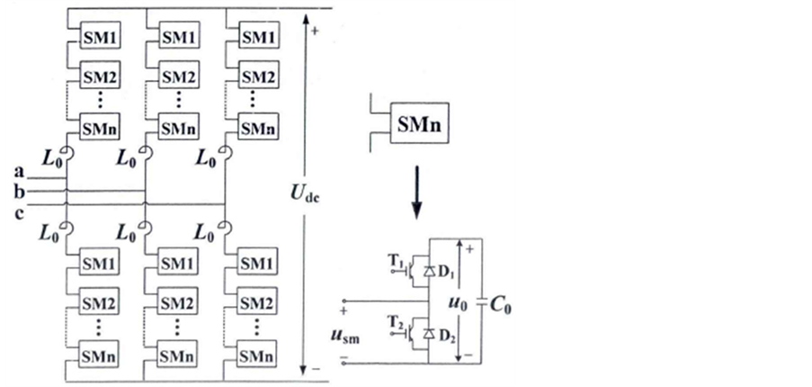
Figure 2. Topology structure of MMC.
project in San Francisco [1].
The essential differences of structure bring MMC a significant performance improvement compared with the traditional two level and three level converter, which listed as follow: [5]
1) Higher quality output voltage waveform. By adjusting the number of sub- modules in series, MMC system can achieve flexible changes in voltage and power levels, which provide a smooth output voltage wave that similar with ideal sine wave.
2) Less impact caused by DC fault. Because of the inductance on the bridge arms, when the DC side occurs a short-circuit fault, the converter bridge arm through the short-circuit current is lower than that in two or three levels converters [6].
3) Lower switching devices requirements. Modular structure makes it ask for lower requirement and easy to package and expand. Traditional two or three levels converters need each IGBT open and close at the same time because of its series structure.
4) Lower switching losses. Switching frequency in MMC can be reduced to 100 Hz - 300 Hz, so it has lower switching losses and enhances the economy.
3. Fault of MTDC
The application of high-power voltage-source converters (VSCs) to MTDC systems is attracting research interest. However, faults occurring along the interconnecting dc cables are most likely to threaten system operation., which effects safety and stability of MTDC networks [7].
Considering the location and the impact of the failure, faults can be divided into line-to-ground, line-to-line, overcurrent and overvoltage faults [8].
A line-to-ground fault (ground fault) occurs when the positive or negative line is shorted to ground. In overhead lines faults may occur when lightning strikes the line or objects falling onto the line, causing a path to ground. In some cases, when the path can be cleared away from the line and the system can be restored. If the fault persists the line would have to be taken out of service until the fault path can be cleared.
When a line-to-ground fault occurs, the faulted pole rapidly discharges capacitor to ground. This causes an imbalance of the DC link voltage between the positive and negative poles. As the voltage of the faulted line begins to fall, high currents flow from the capacitor as well as the AC grid. These high currents may damage the capacitors and the converter.
As stated before, a line-to-line fault on a cable-connected system is less likely to occur on the cable. In an overhead system, line-to-line faults can be caused by an object falling across the positive and negative line, they may also occur in the event of the failure of a switching device causing the lines to short. A switching fault, which is independent of how the converter stations are connected together, causes the positive bus to short to the negative bus inside the converter. A line-to-line fault may be either temporary or permanent.
While overcurrent protection is important during line-to-line and line-to- ground faults, it must also operate when the system is being overloaded. Overload conditions may occur in two-terminal systems when the load increases past the rating of the converter or as a result of a fault on another part of the system. For example, if three VSC’s are feeding a common load and one VSC is dropped due to a permanent fault, the remaining two must supply the load [9]. This will result in elevated currents that may overload the converters. In this situation the overcurrent protection would need to operate. Another option to avoid a wide spread blackout would be to shed non-critical loads.
Overvoltages may occur in overload or in fault conditions. Overvoltages are only a concern during line-to-ground faults. When the fault occurs, the capacitor discharges rapidly to ground. The current flows through the ground then back to the unfaulted line and finally back to the source, which causes the voltage on the healthy pole to increase to 2 pu. Overvoltage is also a concern during the loss of a converter. The loss of an inverter can cause voltage spikes due to excessive power, quickly charging the DC link capacitors. A rectifier loss is only of concern when the loss is temporary. When the rectifier returns suddenly it can cause overvoltages similar to that of an inverter loss.
4. Simulation
The simulation models were made by MATLAB/Simulink, and the VSC-MTDC and MMC-MTDC models were build up in Figure 3.
Four cases simulations had been build up which listed in Table 1.
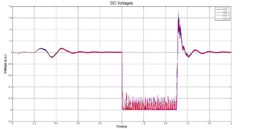
4.1. Case 1: VSC-MTDC Pole to Pole Fault and the Converter Did Not Block after the Fault
In this case, the DC fault locate is the middle of the DC line and the fault duration is 0.5 s. It can be seen in Figure 4 that the DC voltages reached about 1.8 pu

Figure 3. Diagram of faults.
 (a)
(a) (b)
(b)
Figure 4. VSC-MTDC pole to pole fault located in the middle of the DC line. (a) DC voltages. (b) DC currents.
and the DC currents reached about 10.8 pu.
In this case, the DC fault locate is the terminal of the VSC3 and the fault duration is 0.5 s. It can be seen in Figure 5 that the DC voltages reached about 1.75 pu and the DC currents reached about 15 pu, which much higher than a midline-fault.

Table 1. Two cases simulations.
 (a)
(a)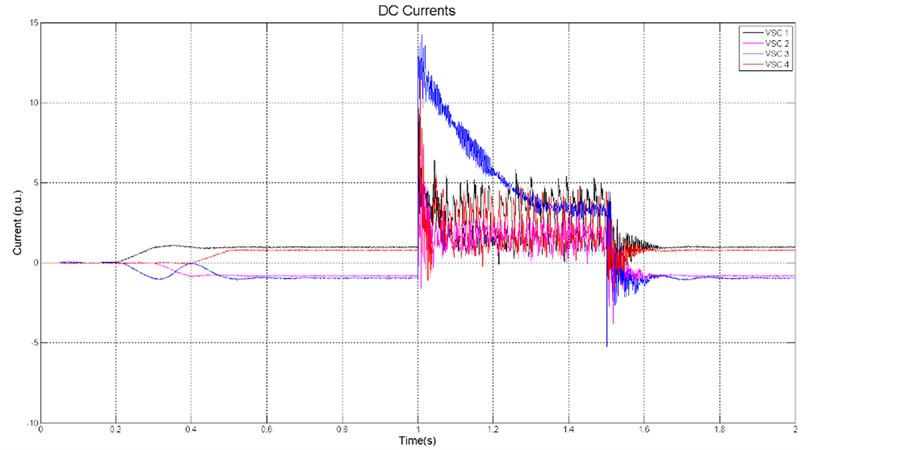 (b)
(b)
Figure 5. VSC-MTDC pole to pole fault located at the terminal of the VSC3. (a) DC voltages. (b) DC currents.
4.2. Case 2: MMC-MTDC Pole to Pole Fault and the Converter Did Not Block after the Fault
In this case, the DC fault locate is the middle of the DC line and the fault duration is 0.5 s. It can be seen in Figure 6 that the DC voltages reached about 1.75 pu and the DC currents reached about 17.5 pu. In this case, the DC fault locate is the terminal of the VSC3 and the fault duration is 0.5 s. It can be seen in Figure 7 that the DC voltage of VSC3 reached about 3.6 pu and the DC current of VSC3 reached about 45 pu.
 (a)
(a) (b)
(b)
Figure 6. MMC-MTDC pole to pole fault located in the middle of the DC line. (a) DC voltages. (b) DC currents.
 (a)
(a) (b)
(b)
Figure 7. MMC-MTDC pole to pole fault located at the terminal of the VSC3. (a) DC voltages. (b) DC currents.
5. Conclusions
In this paper, the structure and characteristics of VSC-MTDC and MMC-MTDC are compared and it can be predicted that MMC-MTDC has bright development prospect with its obvious advantages.
From the simulations of pole-to-pole faults in VSC and MMC-MTDC system, it can be concluded that in a pole-to-pole fault, overvoltage will occur during the recovery process while overcurrent will occur at the beginning of the fault [10].
MMC-MTDC system has its advantages but also has its problem should to
Table 2. The results of simulation.
solve. The simulation results show that pole-to-pole fault in a MMC-MTDC system can lead serious overvoltage and overcurrent. And all the results are listed in Table 2.
Cite this paper
Fan, S.Y., Liu, J., Bian, E.M., Xu, H.T. and Kang, C.L. (2017) Research on DC Fault of Multi-Terminal Direct Current System. Energy and Power Engineering, 9, 756-764. https://doi.org/10.4236/epe.2017.94B081
References
- 1. Lesnicar, R.M. (2003) An Innovative Modular Multilevel Converter Topology Suitable for a Wide Power Range. Power Tech Conference Proceedings, IEEE Bologna, IEEE, 6-11.
- 2. Lu, W. and Ooi, B. (2003) DC Overvoltage Control during Loss of Converter in Multi-Terminal Voltage Sourced Converter Based HVDC. Transactions on Power Delivery, 915-920.
- 3. Wu, J., Wang, Z.X., Xu, L., et al. (2014) Key Technologies of VSC-HVDC and Its Application on Offshore wind Farm in China. Renew Sustain Energy, 36, 247-255. https://doi.org/10.1016/j.rser.2014.04.061
- 4. Davies, M., Dommaschk, M., Dorn, J., et al. (2014) HVDC Pulse Basics and Principle of Operation. Transactions on Power Delivery, IEEE, 327-335.
- 5. Liu, J., He, Z.Y., He, W.G., et al. (2011) The Introduction of Technology of HVDC Based on Modular Multilevel Converter (in Chinese). Power & Energy, 1, 33-38.
- 6. Wang, Z.X., Jiang, C.W., Ai, Q., et al. (2009) The Key Technology of Offshore Wind Farm and Its New Development in China. Renew Sustain Energy, 13, 216-222. https://doi.org/10.1016/j.rser.2007.07.004
- 7. Zhao, C.Y., Chen, X.F., Cao, C.G., et al. (2011) Control and Protection Strategies for MMC-HVDC under DC Faults (in Chinese). Automation of Electric Power Systems, 35, 82-87.
- 8. Mobarrez, M., Kashani, M.G. and Bhattacharya, S. (2016) A Novel Control Approach for Protection of Multi-Terminal VSC-Based HVDC Transmission System against DC Faults. Transactions on Industry Applications, IEEE, 4108-4116. https://doi.org/10.1109/TIA.2016.2565458
- 9. Yang, J., Zheng, J., Tang, G. and He, Z. (2010) Characteristics and Recovery Performance of VSC-HVDC DC Transmission Line Fault. Power and Energy Engineering Conference (APPEEC), IEEE PES Asia-Pacific. IEEE, 1-4.
- 10. Hu, J. (2013) Research on Control Method for Multi-Terminal DC Transmission System Based on MMC. North China Electric Power University, Beijing.