Energy and Power Engineering
Vol.09 No.04(2017), Article ID:75280,11 pages
10.4236/epe.2017.94B032
A Summary Study of Wind Turbine with Related Control
Banghao Zhou, Jianfeng Lu, Kwok Lun Lo
Electronic and Electrical Engineering Department, University of Strathclyde, Glasgow, UK


Received: February 25, 2017; Accepted: March 30, 2017; Published: April 6, 2017
ABSTRACT
One specific issue associated with the wind turbine is how to manage and adjust the rotor speed and pitch angle in the turbine with the wind increasing to achieve the maximum power extraction from the wind. The aim of this paper is to provide a summary study of the impact of related controls and operating strategies on the wind turbine which mean how parameters affect the wind turbine operation. The software of “GH bladed” produced by GL Garrad Hassan will be used to model wind turbine and to perform the analysis. Following two strategies, control of rotor speed and control of blade pitch angle, are applied to the model of the wind turbine to see how output power are adjusted and optimized. The final part proposes the operating strategy of the wind turbine to understand the running procedure of wind turbine inside.
Keywords:
Wind Turbine Power, Wind Power Coefficient, Rotor Speed, Blade Pitch Angle, Operating Strategy

1. Introduction
The development of wind energy is expanding rapidly. In 1887, Prof James Blyth at Anderson’s College, which is named as the University of Strathclyde, installed the first power generating windmill in the world, mentioned in page 65 of [1]. Now, with support for renewable energy, no matter in developed or developing countries, wind energy as a pollution-free energy has attracted many researchers.
The wind turbine turns the blades to spin a shaft in order to lead generator to produce electricity. It is reported that the largest turbine is wider than a football stadium which could be used to support the power of 1400 homes. However, with huge wind installed capacities increasing, all wind farms have to face the same problem, which is the curtailment of wind power output. Recently, wind power curtailment happens more and more frequently since the uncertainty of the wind energy and the mismatching of power grid construction. It is reported [2] that the ratio of curtailment of wind power was about 12% in 2011 and 17% in 2012 at the eastern Inner Mongol in China. Sometimes, this number could reach to 50% during the heating seasons. So the control and operating strategy of wind power become more and more important than before. Actually, the main methods of wind turbine control are adjusting rotor speed and blade pitch angle to achieve rated power output. And more information about certain control methods could be found in [3].
This article deals with a review of how to track maximum power output of the wind turbine through rotor speed control and pitch angle control. Because the function of a wind turbine is extracting power from the wind to convert electrical power, the analysis begins from the equations of power in the wind and then follows the logic of these equations to think step by step. Secondly, Betz Limit, wind power coefficient, as the connection part between power in the wind and wind turbine output is analyzed to understand. Following how to trace this maximum limit by searching suitable tip speed ratio to achieve ideal rated power output is discussed as well. More relationships between tip speed ratio and rotor speed could be found in [4] and [5]. Because how much power output depends on the power coefficient curve and this power coefficient curve is affected by the rotor speed of generator and blade pitch angle. Two main controls of rotor speed and pitch angle are analyzed. Finally, it is necessary to support a whole control strategy during wind turbine operating procedure. So this paper proposes a procedure graph to easy understand how to manage the rated power output and the control orders of speed control and pitch angle control.
2. Wind Turbine Power
Wind turbines work by converting the kinetic energy of wind into kinetic energy of rotor in the turbine. The main conversion energy depends on how much speed of the wind and the swept area of the blade. It is necessary to know the expected power produced and energy output of wind turbine when the wind farm is planning to build.
2.1. Power in the Wind
The procedures of equation deduction below are from [6], and they are used to introduce how to calculate the rated power of wind turbine. Actually, this final equation is same to the equation of power in the wind.
 (1)
(1)
Equation (1) is based on Work Done, where “E” is kinetic energy, “W” is work done on the object, “F” is force and “s” is distance.
 (2)
(2)
Equation (2) is based on Newton’s Law, where “m” is mass, and “a” is accelerated velocity.
 (3)
(3)
Equation (3) is based on Motion Equation, where “u” is initial velocity.
Because of the initial velocity “u” here is zero, following equation could be achieved:
 .
.

Finally, put the value of  into the Equations (1) and (2), then:
 (4)
(4)
Equation (4) is based on Kinetic Energy, then the power in the wind is given by the rate of change of energy below:
 (5)
(5)
 (6)
(6)
Equation (6) is based on mass flow rate, where “ ” is density, and “A” is the mass area.
 (7)
(7)
Equation (7) is based on the rate of change of distance.
Then the power in the wind could be written as Equation (8) by combining the Equations (5) (6) and (7).
 (8)
(8)
Here it is found that this Equation (8) is the maximum theoretical power in the wind, where “ ” is air density of wind, “A” is the area of wind pass, and “v” is the wind speed. If this equation is used in the calculation of power of wind turbine. The “A” should be swept circle area of blade of wind turbine.
 (9)
(9)
Equation (9) is based on the area of a circle, where “ ” is mathematical constant of circle, and “r” is blade radius.
2.2. Wind Power Coefficient
However, it is reported that no wind turbine could convert more than 59.3% of the kinetic energy of the wind into mechanical energy turning a rotor by a German physicist, Albert Betz. In 1928 he said that the theoretical maximum power efficiency of a wind turbine is defined as 59.3 percent. These words are known as the Betz Limit or Betz’ Law. Further information and detail could be found in [7]. For the part of equation in the wind power, Betz Limit is also named as power coefficient  which means effectively ratio of power output from the turbine to the theoretical power in the wind. So, finally, the equation of theoretical extractable power from wind turbine could be defined as:
 (10)
(10)
where “ ” is air density of wind, “A” is the area swept of rotor blade, and “v” is the wind speed.
Power coefficient is a function of the tip speed ratio and the pitch angle:
 (11)
(11)
where, in Equation (11), “ ” is tip speed ratio, “
 ” is turbine rotation speed, “R’ is the radius of the blade and “
 ” is actual speed of the wind.
The figure below is wind power coefficient curve, which is plotted from GH wind turbine model. After running the model, extracting values of coefficient and corresponding values of tip speed ratio. Finally, plotting their related curve (Figure 1). And in this model, the database of rated power, density, blade area are set as 2 Megawatts, 1.225 Kilograms per cubic meter, 5026.5 square meters respectively.
The figure above shows the maximum  is 0.4581 and corresponding tip-speed ratio λ is 7.8. Actually, every point in the curve means each situation of turbine operation. The power coefficient
  extracted here, could be used to calculate corresponding rotor speed. The maximum
  means maximum theoretical efficiency of the wind turbine. And the Equation (10) could explain the reason as well. Generally, control method is used generator torque to change the rotor speed while the wind speed fluctuates in order to track peak power. And its corresponding rotor speed is the ideal rotor speed which achieves the maximum rated wind power output. Related reference of rotor speed control could be found in [8] and [9].

Figure 1. Power coefficient versus tip speed ratio.
After the calculation through the Equation (10), the value of ideal wind speed is 11.2348 meters per second. And in this model, the value of tip speed ratio, the radius of the blade and rated wind speed are 7.8, 40 meters and 11.2348 meters per second. In the ideal wind speed region, the main target of a wind turbine is to maximize the power extraction from the wind energy. After calculation, the best rotor speed is 2.19 radians per second. Except forone advantage of maximum power output, another big advantage of a peak constant rotation speed in generator could allow the wind turbine to connect with a transmission system safely.
The speed of rotation of a wind turbine is often measured by two different methods, rotation speed with unit of revolutions per minute (rpm) or angular velocity with unit of radians per second . The relationship between rotation speed and angular velocity is listed below:
 (12)
(12)
A kind of measure of wind turbine rotor speed is tip speed, which is the tangential velocity of the rotor at the tip of the blades, measured in meters per second. Tip speed ratio is known as a non-dimensional ratio which is using tip speed to divide the undisturbed wind velocity, upstream of the rotor. The equation is listed below:
 (13)
(13)
where “u” is tip speed and “ ” is the undisturbed wind velocity.
So finally, it is concluded that power coefficient  is a function of the value of both tip speed ratio
  and pitch angle
 .
.
3. Control Strategy
This chapter shows two control conceptions, rotor speed control, and pitch angle control. They both are good methods to adjust output power, which means adjusting the rotational speed of the generator or the pitch angle of the blade to optimize and limit the power extracted from the wind.
3.1. Rotor Speed Control
The power coefficient cannot be held in the maximum value (top point of power coefficient) if the rotor speed does not change with the wind speed increasing. In fact, this type of wind turbine is named as fixed speed wind turbine because they operate at a constant rotor speed. However, variable speed control could make the wind turbine always operate close the point of maximum power coefficient since variable rotor speed control, such as the figure [10] below shows.
By analyzing the Figure 2 above it is found that the maximum point of power output is hard to achieve with the rotor speed increasing, which means that the bigger rotor speed the larger wind speed needed to achieve maximum power coefficient. This could be explained by the following part analysis of the impact

Figure 2. Power output curves for different rotor speeds and wind speeds.
of adjusting the synchronousrotational speed of the generator. The diagram below is plotted from extracting the power output curve under rotor speeds of 1250 rpm, 1500 rpm, and 2000 rpm respectively.
From the Figure 3 above three power curves have a same rated power of 2 MW and they have almost thesame power regulation regions (right half side) even under different speeds. But in power output region (left half side) their line trends are quite different and they cross each other at different points. During wind speed range from 4 meters per second to 9 meters per second (low mean wind speed) the generator with a speed of 1250 revolutions per minute works better since this curve shows an earlier growth of power output. However, when the wind speed is larger than 10 meters per second (high mean wind speed) this design shows a bad performance. When wind speed is larger than 9 meters per second (high mean wind speed) the generator with a speed of 1500 revolutions per minute will be the best choice since this curve shows faster increasing. For the part of the generator with a speed of 2000 revolutions per minute, it shows a lower work efficiency which means the turbine needs larger wind speed to achieve corresponding power output when the wind speed is lower than 11 meters per second. However, when the wind speed is larger than 11 meters per second, it shows better performance than the generator with a speed of 1250 revolutions per minute.
Sometimes, to prevent over speeding and overloading problems, constant speed method is applied to limit the rotor speed. However, if the rotor speed is constant, power coefficient  would decrease with the increasing of wind speed. Then, the power extraction decreases with the worked point
  moves to the left side of maximum point. So balancing this characteristic, a good and suitable rotor speed control should be designed to match the variable wind speed
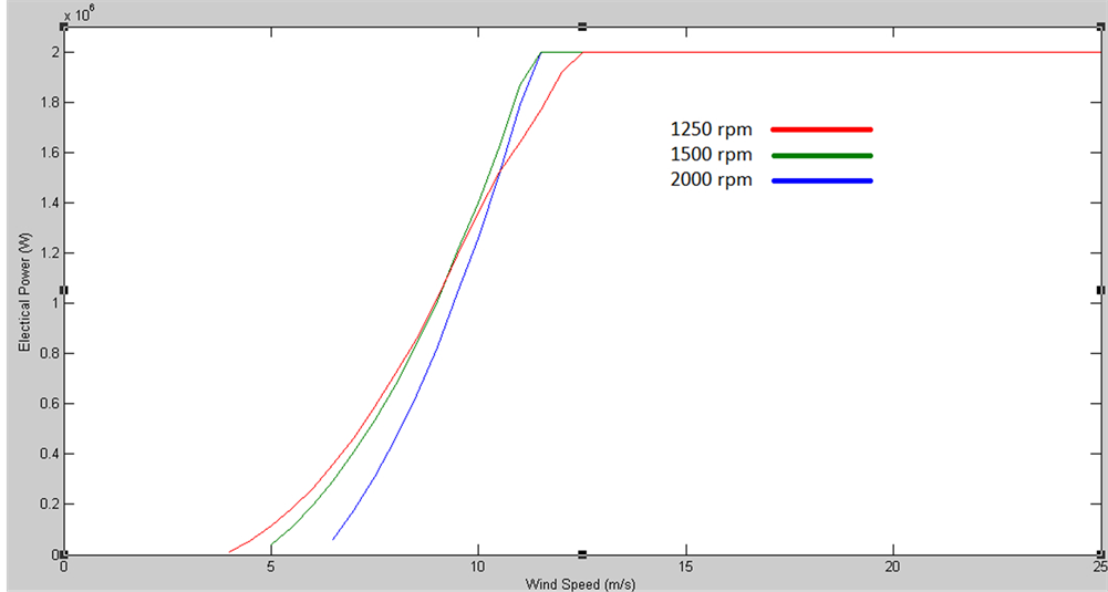
Figure 3. Power output curves for different variable speeds.
to support a better efficiency though the help of changing rotor speed to track the maximum power coefficient under different requirements of system.
3.2. Blade Pitch Angle Control
The pitch angle control adjusts the blade pitch angle to control the wind turbine when the wind speed is larger than the ideal speed. Further details about controller could be found in [11]. The following figure [2] is used to show how the power coefficient  is affected by the changes of pitch angle.
It is obvious to see that (Figure 4), when the pitch angle increases, the maximum Power coefficient will decrease. Besides this, with the power coefficient curve moving down if the related tip speed ratio is not adjusted to match the maximum power coefficient, the power output of wind turbine will decrease rapidly.
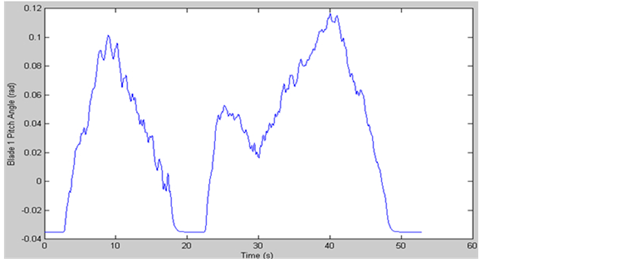
The diagrams below are plotted by extracting data from pitch angle changes of one of three blades from GH wind turbine model and hub wind speed (corresponding values of wind speed). And they work in a same period of time. The hub wind speed means how much wind speed is needed when the rated power output is set in.
It is found that the main trends of increasing and decreasing are same by comparing with two curves above and they achieves the largest value at almost same time points (time of 10, 25 and 40) (Figure 5(a) & Figure 5(b)). So it shows that the bigger pitch angle increases the larger wind speed is required to achieve the maximum output. In addition, the small changes of corresponding pitch angle affect the corresponding values of hub speed obviously. For example, value changes of pitch angle from 0 to 0.1 rad affect the value changes of hub

Figure 4. Power coefficient curves versus tip speed ratio for different pitch angles.
 (a)
(a)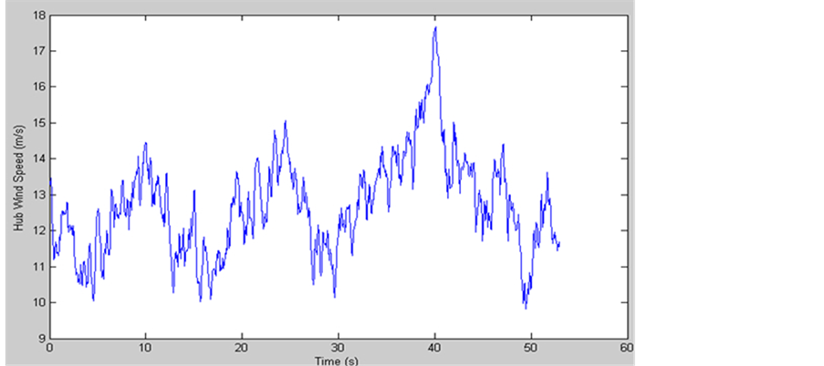 (b)
(b)
Figure 5. (a) Diagrams of blade 1 pitch angle versus time period. (b) Diagrams of hub wind speed versus time period.
wind speed from approximately 12 to 14 meters per second.
So according to the effects of characteristics changes, the control of pitch angle could be used to help wind turbine to adapt the various level of wind speeds. For instance, if the wind is so strong, increasing the corresponding pitch angle to avoid the large rotor speed to damage the system or generator of the wind turbine. And it also could be used to optimize and adjust the maximum power production when the rated output is required. This is why most of the large wind turbines prefer variable pitch blades.
4. Wind Turbine Operating Strategy
The operating strategy not only brings more profit but also safe operation. This (Figure 6(a) & Figure 6(b)) below supports another aspect to look inside the procedure of turbine works by tracing relationships between the values of aerodynamic torque and rotor speed. These related curves below show the ideal situation and actual performance after optimized control by extracting values of aerodynamic torque and rotor speed from the GH wind turbine model.
Table 1 shows ideal and actual values of rotor speed and aerodynamic torque at the switching points, A, B, C and D. First constant speed region is from point A to B, second constant speed region is from point C to D,  tracking region is from point B to C and pitching region is point D.
In the first constant speed region, the wind turbine starts to generate power. During this period, remaining constant rotor speed at minimum speed until the wind speed breaks the threshold value (cut-in wind speed). In the  tracking region, with wind speed increasing rotor speed increases as well until the rotor speed reaches the rated speed. As the reason of the tip speed ratio
  affects the power out, introduced by the chapter 2.2, the strategy here is adjusting the generator electromagnetic torque and controlling tip speed ratio to remain the power coefficient
  at its constant and maximum point to achieve the highest efficiency. In the second constant speed region, because the requirement [12] of operation stability of transmission system is the rated power output to the grid, the strategy here is adjusting the generator electromagnetic torque to control the rotor speed at a constant value to output constant power even growth of wind speed. In the pitching region, with the wind speed still increasing, generator electromagnetic torque is hard to adjust. The strategy here is controlling the pitch angle to reduce power coefficient
  to ensure steady operation of wind turbine.
The torque control has been researched in [13], which is suitable for the large inertia wind turbine based on their two advantages of low impact characteristic toan electro-mechanical system and easy to measure. The principle of torque control is to track maximum power point by adjusting the generator electromagnetic torque output following the aerodynamic optimal torque timely.
5. Conclusion
It is necessary to support a constant power output to the power grid to remain
 (a)
(a) (b)
(b)
Figure 6. (a) Diagrams of ideal values of torque versus rotor speed. (b) Diagrams of actual values of torque versus rotor speed.

Table 1. Rotor speed and aerodynamic torque in the case model.
steady operation even the wind speed is variable. In this paper, by researching the operation procedure of wind turbine, it shows a clearly logic to demonstratehowrated or demand power output of wind turbine is well managed and promoted through the methods of controlling the rotor speed and pitch angle. It is proved that these methods are efficient to reduce curtailment and make system stable operate as two improvements, growth of power output and adjustment of rated power output.
Cite this paper
Zhou, B.H., Lu, J.F. and Lo, K.L. (2017) A Summary Study of Wind Turbine with Related Control Energy and Power Engineering, 9, 270-280. https://doi.org/10.4236/epe.2017.94B032
References
- 1. Liu, Z. (2015) Global Energy Interconnection. Academic Press.
- 2. Zhou, Z.C. and Wang, C.S. (2014) Output Power Curtailment Control of Variable-Speed Variable-Pitch Wind Turbine Generators.Power and Energy Engineering Conference (APPEEC), 2014 IEEE PES Asia-Pacific..
- 3. Johnson, K.E., et al. (2006) Control of Variable-Speed Wind Turbines: Standard and Adaptive Techniques for Maximizing Energy Capture.IEEE Control Systems, 26,. 70-81.https://doi.org/10.1109/MCS.2006.1636311
- 4. Rodriguez-Amenedo, J.L., Arnalte,S. and Burgos, J.C. (2002) Automatic Generation Control of A Wind Farm with Variable Speed Wind Turbines.IEEE Transactions on Energy Conversion, 17, 279-284.https://doi.org/10.1109/TEC.2002.1009481
- 5. Chang-Chien, L.-R. and Y.-C. Yin.(2009) Strategies for Operating Wind Power in A Similar Manner of Conventional Power Plant.IEEE Transactions on Energy Conversion, 24,926-934.https://doi.org/10.1109/TEC.2009.2026609
- 6. Bird, J. (2007)Higher Engineering Mathematics. Routledge.
- 7. Abe, K., et al.(2005) Experimental and Numerical Investigations of Flow Fields behind A Small Wind Turbine with A Flanged Diffuser.Journal of Wind Engineering and Industrial Aerodynamics, 93, 951-970. https://doi.org/10.1016/j.jweia.2005.09.003
- 8. Miller, A., Muljadi, E.and D.S. Zinger. (1997) AVariable Speed Wind Turbine Power Control. IEEE Transactions on Energy Conversion, 12, 181-186.https://doi.org/10.1109/60.629701
- 9. Miller, N.W., et al. (2003)Dynamic Zodeling of GE 1.5 and 3.6 MW Wind TurBine-generators for Stability Simulations. Power Engineering Society General Meeting, 2003, IEEE.
- 10. Salles, M.B., Cardoso, J.R.and Hameyer, K. (2011) Dynamic Modeling of Transverse Flux Permanent Magnet Generator for Wind Turbines.Journal of Microwaves, Optoelectronics and Electromagnetic Applications, 10, 95-105. https://doi.org/10.1590/S2179-10742011000100010
- 11. Zhang, J., et al. Pitch Angle Control for Variable Speed Wind Turbines. Electric Utility Deregulation and Restructuring and Power Technologies, 2008. DRPT 2008. Third International Conference on. 2008. IEEE.
- 12. Channel, I. (2013)General Administration of Quality Supervision, Inspection and Quarantine of the People’s Republic of China.
- 13. Jingfeng, M., et al. Maximum Power Point Trackingin Variable Speed Wind Turbine System via Optimal Torque Sliding Mode Control Strategy.Control Conference (CCC), 2015 34th Chinese. 2015. IEEE.