Paper Menu >>
Journal Menu >>
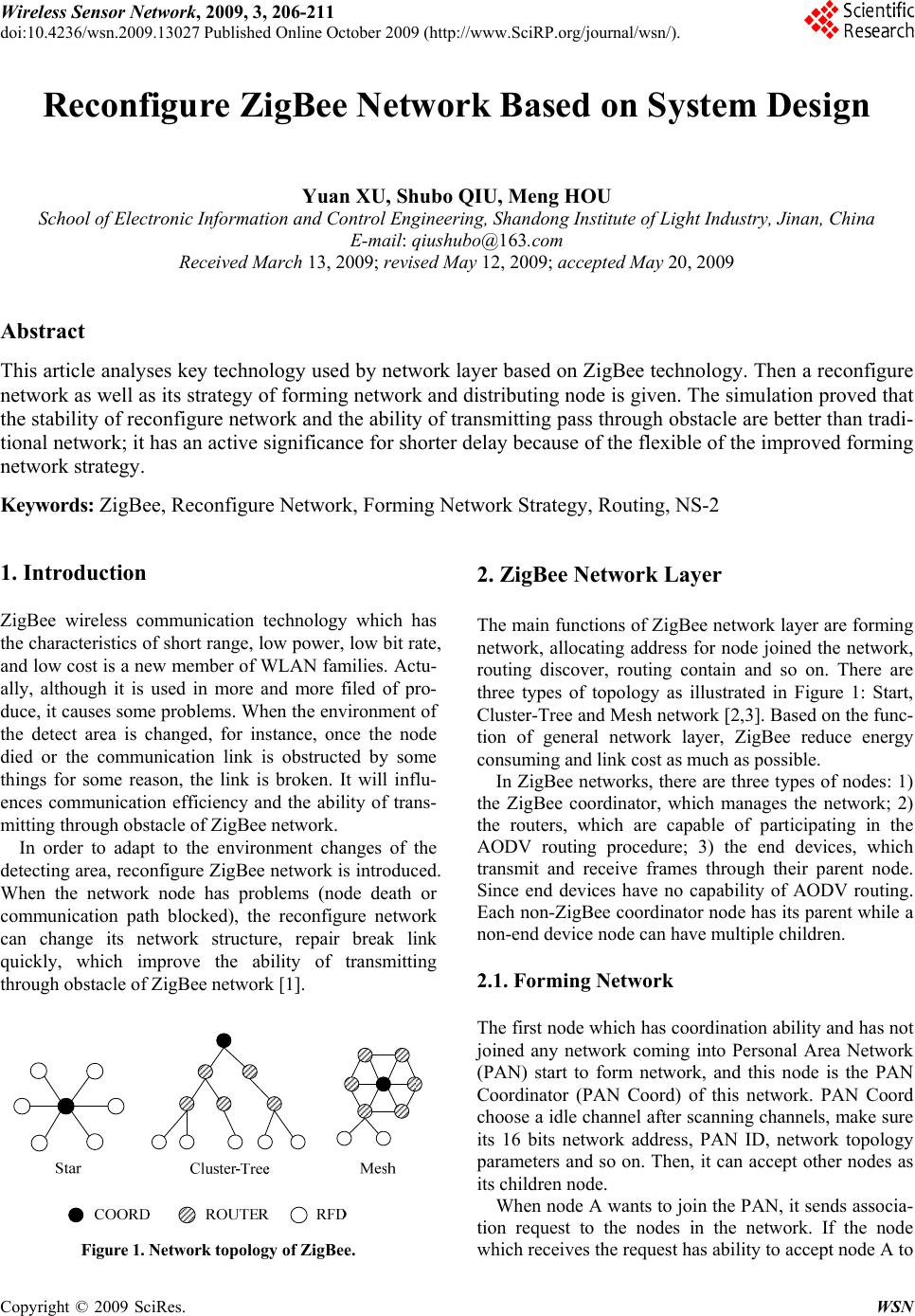 Wireless Sensor Network, 2009, 3, 206-211 doi:10.4236/wsn.2009.13027 ctober 2009 (http://www.SciRP.org/journal/wsn/). Copyright © 2009 SciRes. WSN Published Online O Reconfigure ZigBee Network Based on System Design Yuan XU, Shubo QIU, Meng HOU School of Electronic Information and Control Engineering, Shandong Institute of Light Industry, Jinan, China E-mail: qiushubo@163.com Received March 13, 2009; revised May 12, 2009; accepted May 20, 2009 Abstract This article analyses key technology used by network layer based on ZigBee technology. Then a reconfigure network as well as its strategy of forming network and distributing node is given. The simulation proved that the stability of reconfigure network and the ability of transmitting pass through obstacle are better than tradi- tional network; it has an active significance for shorter delay because of the flexible of the improved forming network strategy. Keywords: ZigBee, Reconfigure Network, Forming Network Strategy, Routing, NS-2 1. Introduction ZigBee wireless communication technology which has the characteristics of short range, low power, low bit rate, and low cost is a new member of WLAN families. Actu- ally, although it is used in more and more filed of pro- duce, it causes some problems. When the environment of the detect area is changed, for instance, once the node died or the communication link is obstructed by some things for some reason, the link is broken. It will influ- ences communication efficiency and the ability of trans- mitting through obstacle of ZigBee network. In order to adapt to the environment changes of the detecting area, reconfigure ZigBee network is introduced. When the network node has problems (node death or communication path blocked), the reconfigure network can change its network structure, repair break link quickly, which improve the ability of transmitting through obstacle of ZigBee network [1]. Figure 1. Network topology of ZigBee. 2. ZigBee Network Layer The main functions of ZigBee network layer are forming network, allocating address for node joined the network, routing discover, routing contain and so on. There are three types of topology as illustrated in Figure 1: Start, Cluster-Tree and Mesh network [2,3]. Based on the func- tion of general network layer, ZigBee reduce energy consuming and link cost as much as possible. In ZigBee networks, there are three types of nodes: 1) the ZigBee coordinator, which manages the network; 2) the routers, which are capable of participating in the AODV routing procedure; 3) the end devices, which transmit and receive frames through their parent node. Since end devices have no capability of AODV routing. Each non-ZigBee coordinator node has its parent while a non-end device node can have multiple children. 2.1. Forming Network The first node which has coordination ability and has not joined any network coming into Personal Area Network (PAN) start to form network, and this node is the PAN Coordinator (PAN Coord) of this network. PAN Coord choose a idle channel after scanning channels, make sure its 16 bits network address, PAN ID, network topology parameters and so on. Then, it can accept other nodes as its children node. When node A wants to join the PAN, it sends associa- tion request to the nodes in the network. If the node which receives the request has ability to accept node A to 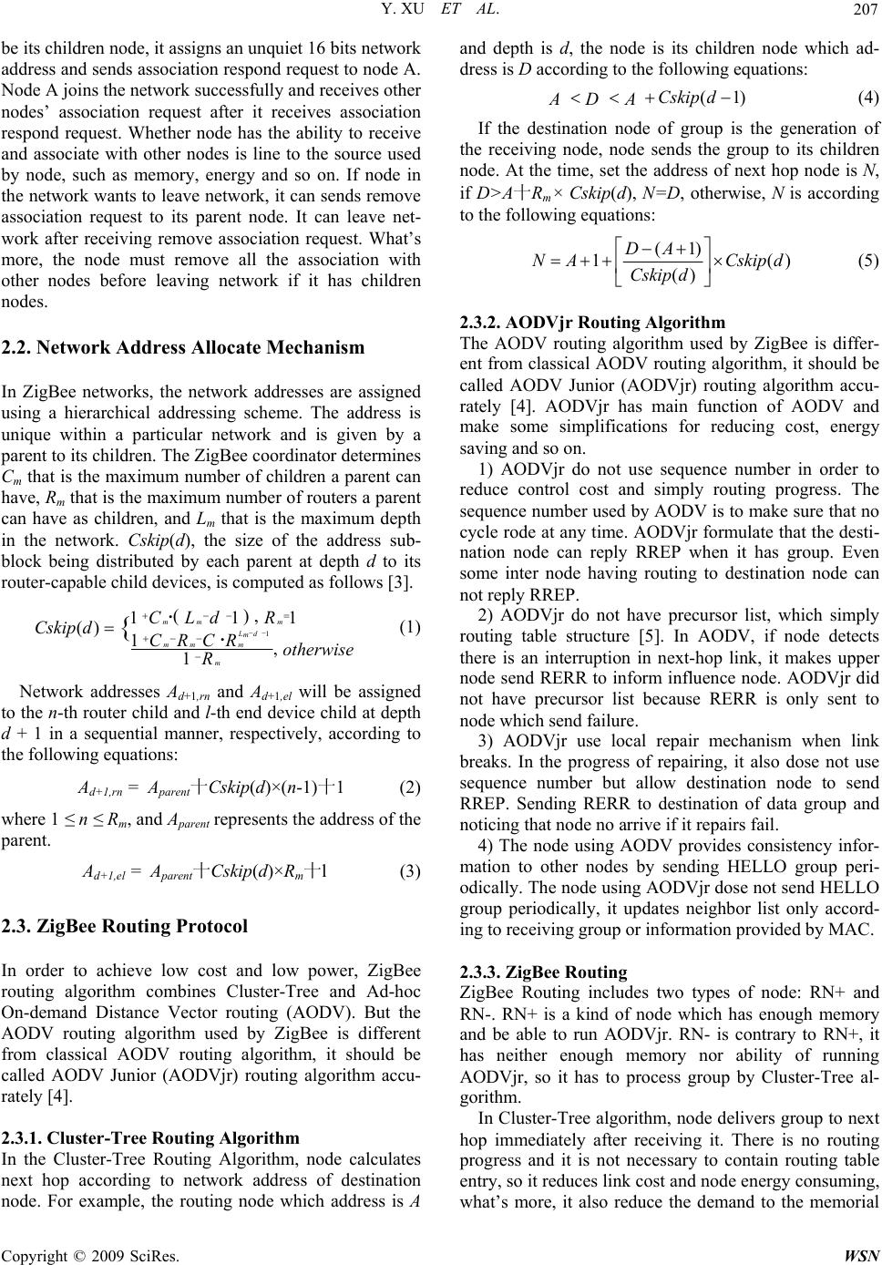 Y. XU ET AL. 207 be its children node, it assigns an unquiet 16 bits network address and sends association respond request to node A. Node A joins the network successfully and receives other nodes’ association request after it receives association respond request. Whether node has the ability to receive and associate with other nodes is line to the source used by node, such as memory, energy and so on. If node in the network wants to leave network, it can sends remove association request to its parent node. It can leave net- work after receiving remove association request. What’s more, the node must remove all the association with other nodes before leaving network if it has children nodes. 2.2. Network Address Allocate Mechanism In ZigBee networks, the network addresses are assigned using a hierarchical addressing scheme. The address is unique within a particular network and is given by a parent to its children. The ZigBee coordinator determines Cm that is the maximum number of children a parent can have, Rm that is the maximum number of routers a parent can have as children, and Lm that is the maximum depth in the network. Cskip(d), the size of the address sub- block being distributed by each parent at depth d to its router-capable child devices, is computed as follows [3]. 1 () , 111 () 1, 1 {mm m d Lm mm m m Cd LR Cskip dCC RR otherwise R (1) Network addresses Ad+1,rn and Ad+1,el will be assigned to the n-th router child and l-th end device child at depth d + 1 in a sequential manner, respectively, according to the following equations: Ad+1,rn = Aparent十Cskip(d)×(n-1)十1 (2) where 1 ≤ n ≤ Rm, and Aparent represents the address of the parent. Ad+1,el = Aparent十Cskip(d)×Rm十l (3) 2.3. ZigBee Routing Protocol In order to achieve low cost and low power, ZigBee routing algorithm combines Cluster-Tree and Ad-hoc On-demand Distance Vector routing (AODV). But the AODV routing algorithm used by ZigBee is different from classical AODV routing algorithm, it should be called AODV Junior (AODVjr) routing algorithm accu- rately [4]. 2.3.1. Cluster-Tree Routing Algorithm In the Cluster-Tree Routing Algorithm, node calculates next hop according to network address of destination node. For example, the routing node which address is A and depth is d, the node is its children node which ad- dress is D according to the following equations: (1Cskip d ADA) (4) If the destination node of group is the generation of the receiving node, node sends the group to its children node. At the time, set the address of next hop node is N, if D>A十Rm× Cskip(d), N=D, otherwise, N is according to the following equations: )( )( )1( 1dCskip dCskip AD AN (5) 2.3.2. AODVjr Routing Algorithm The AODV routing algorithm used by ZigBee is differ- ent from classical AODV routing algorithm, it should be called AODV Junior (AODVjr) routing algorithm accu- rately [4]. AODVjr has main function of AODV and make some simplifications for reducing cost, energy saving and so on. 1) AODVjr do not use sequence number in order to reduce control cost and simply routing progress. The sequence number used by AODV is to make sure that no cycle rode at any time. AODVjr formulate that the desti- nation node can reply RREP when it has group. Even some inter node having routing to destination node can not reply RREP. 2) AODVjr do not have precursor list, which simply routing table structure [5]. In AODV, if node detects there is an interruption in next-hop link, it makes upper node send RERR to inform influence node. AODVjr did not have precursor list because RERR is only sent to node which send failure. 3) AODVjr use local repair mechanism when link breaks. In the progress of repairing, it also dose not use sequence number but allow destination node to send RREP. Sending RERR to destination of data group and noticing that node no arrive if it repairs fail. 4) The node using AODV provides consistency infor- mation to other nodes by sending HELLO group peri- odically. The node using AODVjr dose not send HELLO group periodically, it updates neighbor list only accord- ing to receiving group or information provided by MAC. 2.3.3. ZigBee Routing ZigBee Routing includes two types of node: RN+ and RN-. RN+ is a kind of node which has enough memory and be able to run AODVjr. RN- is contrary to RN+, it has neither enough memory nor ability of running AODVjr, so it has to process group by Cluster-Tree al- gorithm. In Cluster-Tree algorithm, node delivers group to next hop immediately after receiving it. There is no routing progress and it is not necessary to contain routing table entry, so it reduces link cost and node energy consuming, what’s more, it also reduce the demand to the memorial C opyright © 2009 SciRes. WSN  Y. XU ET AL. Copyright © 2009 SciRes. WSN 208 ability of a node. However, because the link which built by Cluster-Tree may not be the best optimize link, the delay of deliver is big. The lower the depth of the node is, the more node works, and it makes assignment of com- munication flow unbalance. ZigBee routing allow RN+ to seek the best optimize link: RN+ start to use routing discover to find the shortest link to the destination node after it receives group, if there are two links have the same hop, node choose the better one according to the LQI which provides by MAC layer of IEEE802.15.4; node deliver group via the link, if there is an interruption in the link, RN+ repair routing by local repair mecha- nism. AODVjr reduce the delay of group deliver and improve reliability of group deliver [6]. 3. Reconfigure ZigBee Network 3.1. Reconfigure Network and Routing Algorithm Reconfigure ZigBee Network is a network that the net- work structure can change dynamic. There are two meanings of structure changing dynamic: 1) the network topology does not change, but the type of node or the depth of network changes, 2) the network topology is changed. According to above, in ZigBee technology, Cluster- Tree algorithm is suit for the node which the memory is limited, node can send the receiving group to its children node or parent node without routing discovery progress, but it have a big per-to-per delay in the network which distribute nodes unbalance, it can causes business flow distribute unbalance. The less the depth of the node is, the more node works, it makes low depth node exhaust its power more quickly and lead communication to break at last. In the contrary, ADOVjr algorithm can seek the best optimize link, reduce per-to-per delay, and relax business flow distribute unbalance. But ADOVjr need more memory to contain routing table and much link cost. Reconfigure network use Cluster-Tree + AODVjr as its routing protocol, which can seek the best optimize link, reduce per-to-per delay, reduce link cost, and relax busi- ness flow distribute unbalance. 3.2. Network Address Allocate Mechanism in Reconfigure Network The reconfigure network use RN+ in order to reconfigure network to adapt the changing environment. The node joined the network form Cluster-Tree by the association provided by MAC layer. When a node allows a new node to join the network, they form parent-children relation; parent node assigns the unique 16 bits network address to children node. The Start topology is descript as a special Cluster-Tree topology (depth is 2) in reconfigure net- work. 3.3. Network Reconfiguration The network reconfiguration is embodied in the condi- tion that the node environment is changing. Node need to reconfigure its network structure to communicate throu- gh obstruct when detect environment is changed. As shown in Figure 2(a), as a result of changing envi- ronment, the communication link between node 7 and node 3 is obstructed in a Cluster-Tree network. Node has to leave network, it can’t transmit data to upper lever node. At this time, node starts to reconfigure network: according to network address allocate mechanism in re- configure network (Equations (1) (2)), compute network address of the node (node 6) with same depth and parent node. Then AODVjr routing algorithm is used for rout- ing for this node. If find node 6, node 7 will join the network as children node of node 6 and re-allocate net- work address. The reconfiguration is finished when the communication link between node 6 and node 7 is built. If there is no node that both depth and parent node are the same around obstructed node (e.g. node 5), node will Figure 2. The forming network strategy of reconfigure Cluster-Tree network. “——”is represent parent-children relation; “()” is represent network address; “+” is represent node RN+, “-” is represent node RN-; Node 0 is PAN Coord, its network address is 0.  Y. XU ET AL. 209 Figure 3. The process of reconfigure network. compute network address of the node (node 4) with same depth but different parent node. Then according to net- work address allocate mechanism in reconfigure network, AODVjr routing algorithm is used for routing for this node. Node 5 will join the network as children node of node 4 and re-allocate network address if find node 4. The reconfiguration is finished when the communication link between node 4 and node 5 is built. Though the network structure is also Cluster-Tree after network con- figuration, the depth of network is changing from 4 to 5, as shown in Figure 2(b). Node 7’s parent node is chang- ing from node 3 to node 6 while node 5’s parent node is changing from node 2 to node 4. The process of recon- figure network is shown in Figure 3. The Start topology is defined as a special Cluster-Tree topology (depth is 2) in reconfigure network. So as shown in Figure 4(a), according to AODVjr routing al- gorithm, node begins routing node 5when the communi- cation between node 4 and coordinator. Node 4 will join the network as children node of node 5 if find node 5 and be re-allocated network address. The reconfiguration is finished when the communication link between node 4 and node 5. As shown in Figure 4(c), the network topol- ogy is changing from Start to Cluster-Tree. The value of network depth is limited. It is consider that the communication link is break and need to repair as long as network depth is over limited value. 3.4. Communication Link Repair Routing across break node is a way of addressing which C opyright © 2009 SciRes. WSN 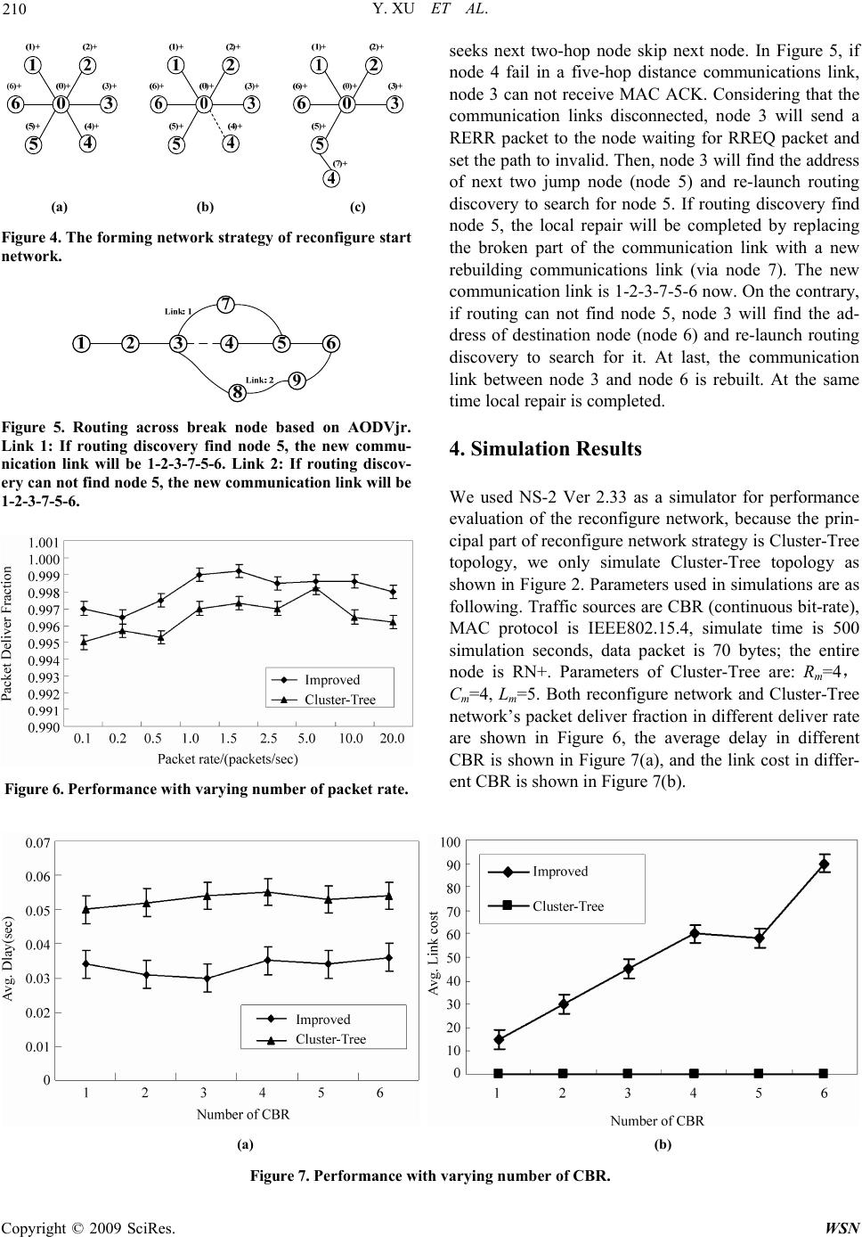 Y. XU ET AL. 210 (a) (b) (c) Figure 4. The forming network strategy of reconfigure start network. Figure 5. Routing across break node based on AODVjr. Link 1: If routing discovery find node 5, the new commu- nication link will be 1-2-3-7-5-6. Link 2: If routing discov- ery can not find node 5, the new communication link will be 1-2-3-7-5-6. Figure 6. Performance with varying number of packet rate. seeks next two-hop node skip next node. In Figure 5, if node 4 fail in a five-hop distance communications link, node 3 can not receive MAC ACK. Considering that the communication links disconnected, node 3 will send a RERR packet to the node waiting for RREQ packet and set the path to invalid. Then, node 3 will find the address of next two jump node (node 5) and re-launch routing discovery to search for node 5. If routing discovery find node 5, the local repair will be completed by replacing the broken part of the communication link with a new rebuilding communications link (via node 7). The new communication link is 1-2-3-7-5-6 now. On the contrary, if routing can not find node 5, node 3 will find the ad- dress of destination node (node 6) and re-launch routing discovery to search for it. At last, the communication link between node 3 and node 6 is rebuilt. At the same time local repair is completed. 4. Simulation Results We used NS-2 Ver 2.33 as a simulator for performance evaluation of the reconfigure network, because the prin- cipal part of reconfigure network strategy is Cluster-Tree topology, we only simulate Cluster-Tree topology as shown in Figure 2. Parameters used in simulations are as following. Traffic sources are CBR (continuous bit-rate), MAC protocol is IEEE802.15.4, simulate time is 500 simulation seconds, data packet is 70 bytes; the entire node is RN+. Parameters of Cluster-Tree are: Rm=4, Cm=4, Lm=5. Both reconfigure network and Cluster-Tree network’s packet deliver fraction in different deliver rate are shown in Figure 6, the average delay in different CBR is shown in Figure 7(a), and the link cost in differ- ent CBR is shown in Figure 7(b). (a) (b) Figure 7. Performance with varying number of CBR. Copyright © 2009 SciRes. WSN 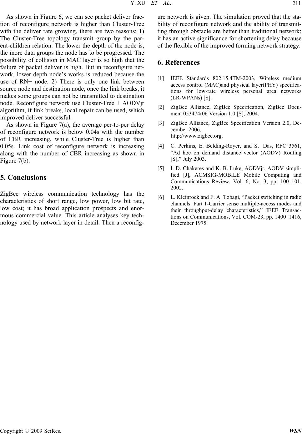 Y. XU ET AL. C opyright © 2009 SciRes. WSN 211 As shown in Figure 6, we can see packet deliver frac- tion of reconfigure network is higher than Cluster-Tree with the deliver rate growing, there are two reasons: 1) The Cluster-Tree topology transmit group by the par- ent-children relation. The lower the depth of the node is, the more data groups the node has to be progressed. The possibility of collision in MAC layer is so high that the failure of packet deliver is high. But in reconfigure net- work, lower depth node’s works is reduced because the use of RN+ node. 2) There is only one link between source node and destination node, once the link breaks, it makes some groups can not be transmitted to destination node. Reconfigure network use Cluster-Tree + AODVjr algorithm, if link breaks, local repair can be used, which improved deliver successful. As shown in Figure 7(a), the average per-to-per delay of reconfigure network is below 0.04s with the number of CBR increasing, while Cluster-Tree is higher than 0.05s. Link cost of reconfigure network is increasing along with the number of CBR increasing as shown in Figure 7(b). 5. Conclusions ZigBee wireless communication technology has the characteristics of short range, low power, low bit rate, low cost; it has broad application prospects and enor- mous commercial value. This article analyses key tech- nology used by network layer in detail. Then a reconfig- ure network is given. The simulation proved that the sta- bility of reconfigure network and the ability of transmit- ting through obstacle are better than traditional network; it has an active significance for shortening delay because of the flexible of the improved forming network strategy. 6. References [1] IEEE Standards 802.15.4TM-2003, Wireless medium access control (MAC)and physical layer(PHY) specifica- tions for low-rate wireless personal area networks (LR-WPANs) [S]. [2] ZigBee Alliance, ZigBee Specification, ZigBee Docu- ment 053474r06 Version 1.0 [S], 2004. [3] ZigBee Alliance, ZigBee Specification Version 2.0, De- cember 2006, http://www.zigbee.org. [4] C. Perkins, E. Belding-Royer, and S.Das, RFC 3561, “Ad hoe on demand distance vector (AODV) Routing [S],” July 2003. [5] I. D. Chakeres and K. B. Luke, AODVjr, AODV simpli- fied [J], ACMSIG-MOBILE Mobile Computing and Communications Review, Vol. 6, No. 3, pp. 100–101, 2002. [6] L. Kleinrock and F. A. Tobagi, “Packet switching in radio channels: Part 1-Carrier sense multiple-access modes and their throughput-delay characteristics,” IEEE Transac- tions on Communications, Vol. COM-23, pp. 1400–1416, December 1975. |