Paper Menu >>
Journal Menu >>
 Journal of Software Engineering and Applications, 2011, 4, 546-549 doi:10.4236/jsea.2011.49063 Published Online September 2011 (http://www.SciRP.org/journal/jsea) Copyright © 2011 SciRes. JSEA Multi-Domain Parallel Computing for Strength Analysis of Whole Aircraft Model Xiuhua Chen, Hai Wang, Yubo Ding School of Aeronautics and Astronautics, Shanghai JiaoTong University, Shanghai, China. Email: chenxiuhua@sjtu.edu.cn Received July 25th, 2011; revised August 20th, 2011; accepted August 28th, 2011. ABSTRACT In the Windows XP 64 bit operating system environment, several common PC were used to build a cluster system, es- tablishing the distributed memory parallel (DMP) computing system. A finite element model of whole aircraft with about 260 million degrees of freedom (DOF) was developed using three-node and four-node thin shell element and two-node beam element. With the large commercial finite element software MSC.MARC and employing two kinds of domain decomposition method (DDM) respectively, realized the parallel solving for the static strength analysis of the whole aircraft model, which offered a high cost-effective solution for solving large-scale and complex finite element models. Keywords: Parallel Computing, Whole Aircraft Model, Static Strengt h , Do m ain Decompo sit ion 1. Introduction With the steady development of domestic aviation indus- try, especially the further research of commercial aircraft engineering, all kinds of large-scale and complex struc- tures are encountered. These structures are not only with huge dimensions but also with more complicated condi- tions, even related to kinds of geometrical, material, contact nonlinearity problems. For these problems, tradi- tional finite element methods (FEM) running on single PC can’t satisfy the need of engineering practice. The technology of parallel computing is introduced into finite element analysis to increase the scale of structure analy- sis, accelerate computing speed, and facilitate the appli- cation of finite element in large-scale and complex structures. Parallel systems and multi-core systems are quite com- mon these days. While most solvers focus on paralleliz- ing only one aspect of solution (namely, matrix solution), MSC.MARC parallelizes all the steps of analysis (as- sembly, matrix solution and stress recovery). This en- ables researchers to get more out of the hardware. Parallel finite element method (FEM) based on domain decomposition method (DDM) is one of the most active research orientations in current parallel computing field. At present, in rock-soil mechanics [1,2], computational fluid dynamics (CFD) [3] and other domains, domestic scholars have carried out extensive research. However, there is scarce engineering practice for strength analysis of large-scale aero structure mainly composed of plate, shell and beam. One reason is that studying to domain decomposition method (DDM) are not enough to make research deep into and few of methods can effectively implement the domain decomposition of large-scale and complex structures. The other is that most of researchers focus on the study of theories and few software available can be applied to practice. This paper practice the spe- cific application in the strength analysis of whole aircraft model with millions node degree of freedom and intro- duce the optimal decomposition method. 2. Establishing of PC Cluster The study in this paper is based on PC cluster and its architecture is shown in Figure 1.The PC cluster is com- posed of one host node and several slave nodes. Both host and slave nodes are used to participate in computing. The PC cluster, with the ability of distributed memory and storage, greatly enhance the performance of the whole system. According to the scale and complexity of the whole aircraft finite element model, one host node and eight slave nodes were used to build the PC cluster. Each node has the same configuration as shown in Table 1. 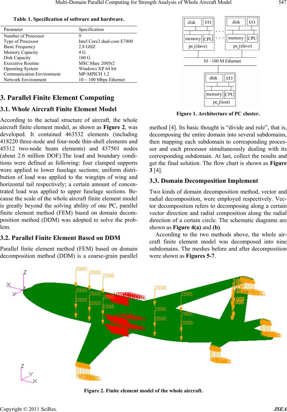 Multi-Domain Parallel Computing for Strength Analysis of Whole Aircraft Model 547 Table 1. Specification of software and hardware. Parameter Specification Number of Processor 9 Type of Processor Intel Core2 dual-core E7400 Basic Frequency 2.8 GHZ Memory Capacity 4 G Disk Capacity 160 G Executive Routine MSC.Marc 2005r2 Operating System Windows XP 64 bit Communication Environment MP-MPICH 1.2 Network Environment 10 ~ 100 Mbps Ethernet 3. Parallel Finite Element Comp uting 3.1. Whole Aircraft Finite Element Model According to the actual structure of aircraft, the whole aircraft finite element model, as shown as Figure 2, was developed. It contained 463532 elements (including 418220 three-node and four-node thin-shell elements and 45312 two-node beam elements) and 437501 nodes (about 2.6 million DOF).The load and boundary condi- tions were defined as following: four clamped supports were applied to lower fuselage sections; uniform distri- bution of load was applied to the wingtips of wing and horizontal tail respectively; a certain amount of concen- trated load was applied to upper fuselage sections. Be- cause the scale of the whole aircraft finite element model is greatly beyond the solving ability of one PC, parallel finite element method (FEM) based on domain decom- position method (DDM) was adopted to solve the prob- lem. 3.2. Parallel Finite Element Based on DDM Parallel finite element method (FEM) based on domain decomposition method (DDM) is a coarse-grain parallel Figure 1. Architecture of PC cluster. method [4]. Its basic thought is “divide and rule”, that is, decomposing the entire domain into several subdomains, then mapping each subdomain to corresponding proces- sor and each processor simultaneously dealing with its corresponding subdomain. At last, collect the results and get the final solution. The flow chart is shown as Figure 3 [4]. 3.3. Domain Decomposition Implement Two kinds of domain decomposition method, vector and radial decomposition, were employed respectively. Vec- tor decomposition refers to decomposing along a certain vector direction and radial composition along the radial direction of a certain circle. The schematic diagrams are shown as Figure 4(a) and (b). According to the two methods above, the whole air- craft finite element model was decomposed into nine subdomains. The meshes before and after decomposition were shown as Figures 5-7. Figure 2. Finite element model of the whole aircraft. Copyright © 2011 SciRes. JSEA 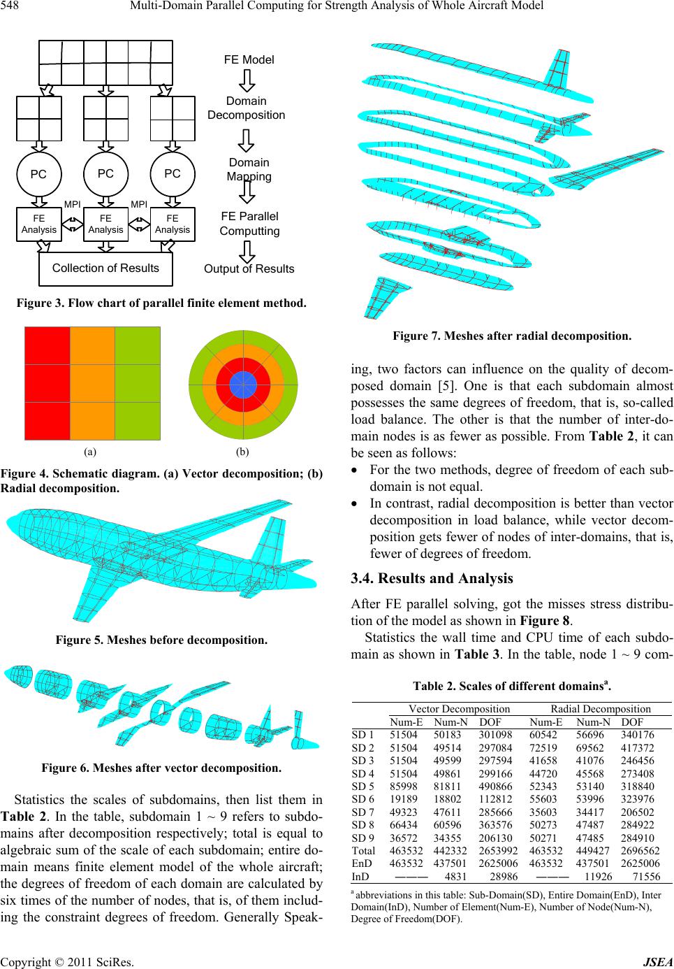 Multi-Domain Parallel Computing for Strength Analysis of Whole Aircraft Model 548 PC Collection of Results PC PC FE Analysis FE Analysis FE Analysis MPI MPI FE Model Domain Decomposition Domain Mapping FE Parallel Computting Output of Results Figure 3. Flow chart of parallel finite element method. (a) (b) Figure 4. Schematic diagram. (a) Vector decomposition; (b) Radial decomposition. Figure 5. Meshes before decomposition. Figure 6. Meshes after vector decomposition. Statistics the scales of subdomains, then list them in Table 2. In the table, subdomain 1 ~ 9 refers to subdo- mains after decomposition respectively; total is equal to algebraic sum of the scale of each subdomain; entire do- main means finite element model of the whole aircraft; the degrees of freedom of each domain are calculated by six times of the number of nodes, that is, of them includ- ing the constraint degrees of freedom. Generally Speak- Figure 7. Meshes after radial decomposition. ing, two factors can influence on the quality of decom- posed domain [5]. One is that each subdomain almost possesses the same degrees of freedom, that is, so-called load balance. The other is that the number of inter-do- main nodes is as fewer as possible. From Table 2, it can be seen as follows: For the two methods, degree of freedom of each sub- domain is not equal. In contrast, radial decomposition is better than vector decomposition in load balance, while vector decom- position gets fewer of nodes of inter-domains, that is, fewer of degrees of freedom. 3.4. Results and Analysis After FE parallel solving, got the misses stress distribu- tion of the model as shown in Figure 8. Statistics the wall time and CPU time of each subdo- main as shown in Table 3 . In the table, node 1 ~ 9 com- Table 2. Scales of different domainsa. Vector Decomposition Radial Decomposition Num-ENum-NDOF Num-E Num-NDOF SD 1 51504 50183 301098 60542 56696 340176 SD 2 51504 49514 297084 72519 69562 417372 SD 3 51504 49599 297594 41658 41076 246456 SD 4 51504 49861 299166 44720 45568 273408 SD 5 85998 81811 490866 52343 53140 318840 SD 6 19189 18802 112812 55603 53996 323976 SD 7 49323 47611 285666 35603 34417 206502 SD 8 66434 60596 363576 50273 47487 284922 SD 9 36572 34355 206130 50271 47485 284910 Total 463532442332 2653992 463532 449427 2696562 EnD 463532437501 2625006 463532 437501 2625006 InD ――― 4831 28986 ――― 1192671556 a abbreviations in this table: Sub-Domain(SD), Entire Domain(EnD), Inter Domain(InD), Number of Element(Num-E), Number of Node(Num-N), Degree of Freedom(DOF). Copyright © 2011 SciRes. JSEA  Multi-Domain Parallel Computing for Strength Analysis of Whole Aircraft Model 549 Figure 8. Mises stress distribution in the whole FEM. Table 3. Computing time of nodes. Vector Decomposition Radial Decomposition Wall Time (s) CPU Time (s) Wall Time (s) CPU Time (s) Node 1 1799.44 840.30 2108.23 1090.50 Node 2 1799.42 567.80 2108.24 662.44 Node 3 1799.34 541.11 2108.11 236.38 Node 4 1799.28 466.86 2108.05 412.12 Node 5 1799.20 824.36 2107.97 485.83 Node 6 1799.14 114.09 2107.92 478.77 Node 7 1799.08 567.73 2107.86 233.42 Node 8 1799.03 633.33 2107.81 642.27 Node 9 1798.97 243.59 2107.74 660.55 Total Time 1846.27 842.09 2154.01 1092.19 puted the corresponding subdomain 1 ~ 9 respectively and total time is the elapsed time to compute the whole model, including total wall time and CPU time. It can be seen from Table 3 that for each computing node, wall time is nearly equal, but the CPU time not. That is de- termined by the load distribution on each computing node and the number of inter-domain nodes. Also, it can be seen from the item of total time that vector decompo- sition has a little advantage, that is, although vector de- composition is not better than radial decomposition in load distribution, the less number of inter-subdomain nodes greatly decrease the total time. Of course, for a model with large scale and high complexity, it is not at ease to achieve both load balance and least communica- tion overhead. In short, taking over half an hour to solve such model successfully on the common PC cluster, no doubt, is high cost-effective. 4. Conclusions PC cluster based on Windows XP 64-bit system is an ideal, high cost-effective parallel system with the ability of distributed memory and storage and able to achieve the parallel solving of large-scale finite element model. Domain decomposition method (DDM) is coarse-grain parallel strategy and fit for PC cluster system. In the sys- tem, each computing node is just in charge of corre- sponding subdomain and only exchanges the information and data in the public area among subdomains. Both vector and radial decomposition is able to decom- pose complex finite element meshes, which is of great significance for the large-scale aero structure mainly com- posed of plate, shell and beam. The choice of domain decomposition method is very important. In order to achieve higher efficiency, two as- pects should meet. One is load balance, and the other is minimizing the number of inter-domain nodes. The com- putational efficiency of parallel finite element method (FEM) based on domain decomposition method (DDM) is determined by the balance of the two aspects above. REFERENCES [1] Y. Zhang, X. Feng and Z. Ru, “Large-Scale High Per- formance Parallel Finite Element System Based on Do- main Decomposition Method In Geo-Mechanics,” Chi- nese Journal of Rock Mechanics and Engineering, Vol. 23, No. 21, 2004, pp. 3636-3641. [2] Y. Guo, X. Jin, J. Ding and W. Cao, “Parallel Processing of Seismic Response Analysis for Immersed Tunnel,” Chinese Journal of Rock Mechanics and Engineering, Vol. 24, No. 15, 2005, pp. 2723-2727. [3] Y. Qi, L. Hu, X. Lin and H. Liu, “Domain Decomposition for Applications Based on CFD-Grid,” Proceedings of the 2004 IEEE International Conference on Services Com- puting, Shanghai, 15-18 September 2004, pp. 592-595. [4] C. Fu, “The Research on Parallel Computation of Finite Element Structural Analysis Based on MPI Cluster,” Ph.D. Thesis, Shanghai University, Shanghai, 2006. [5] W. Qi, X. Jin, X. Zhang, Y. Li and G. Li, “Finite Element Simulation and Performance Study of Vehicle Crash Based Parallel Computing,” Journal of System Simulation, Vol. 16, No. 11, 2004, pp. 2428-2431. Copyright © 2011 SciRes. JSEA |