Journal of Software Engineering and Applications, 2011, 4, 527-533
doi:10.4236/jsea.2011.49061 Published Online September 2011 (http://www.SciRP.org/journal/jsea)
Copyright © 2011 SciRes. JSEA
527
Optimization of Desiccant Absorption System
Using a Genetic Algorithm
Ayman A. Aly1,2
1Mechatronics Section, Mechanical Engineering Department, Faculty of Engineering, Taif University, Al-Haweiah, Saudi Arabia;
2Mechatronics Section, Mechanical Engineering Department, Faculty of Engineering, Assiut University, Assiut, Egypt.
Email: draymanelnaggar@yahoo.com
Received June 30th, 2011; revised July 25th, 2011; accepted August 3rd, 2011.
ABSTRACT
Optimization of the op en absorption desicca nt cooling system has been carried out in the present work. A fin ite differ-
ence method is used to simulate the combined heat and mass transfer processes that occur in the liquid desiccant re-
generator which uses calcium chloride (CaCl2) solution as the working desiccant. The source of input heat is assumed
to be the total radiation in cident on a tilted surface. The system o f equations is solved using the Matlab-Simulink plat-
form. The effect of the important parameters, namely the regenerator length, desiccant solution flow rate and concen-
tration, and air flow rates, on the performance of the system is investigated. In order to optimize the system perform-
ance, a genetic algorithm tech nique has been app lied. The system coefficient o f performance COP ha s been maximized
for different design parameters. It has been found that the maximum values of COP could be obtained for different
combinations of regenerator length solution flow rate and air flow rate. Therefore, it is essential to select the design
parameters for each ambient condition to maximize the performance of the system.
Keywords: Genetic Algorithm, Modeling, Optimization, Solar-Powered, Desiccant
1. Introduction
In hot and humid areas, liquid desiccant air-conditioning
systems have been proposed as alternatives to the con-
ventional vapor compression cooling systems to control
air humidity. Since the introduction of open-cycle liquid-
desiccant absorption solar-cooling system by Kakabaev
and Khandurdyev [1], the system has been investigated
extensively. The feasibility of the system and the advan-
tages it can offer in terms of energy and cost saving have
been proved in different climates (see for example [2-6]).
Among the advantages of liquid-desiccant systems are:
the lower temperature for regeneration, the ease of ma-
nipulation, lower pressure drop in the contactors with the
flowing air, and th e possibility of filtering to remove dirt
taken in from the air [7].
A schematic of an open solar absorption cooling sys-
tem is shown in Figure 1. The weak absorbent solution is
heated and subsequently concentrated in the solar collec-
tor. The strong regenerated solution leaves the collector
and passes through a liquid column, to allow the strong
solution to go from atmospheric pressure to reduced
pressure efficiently. The strong solution then passes
through a regenerative heat exchanger on its way to the
absorber, where it absorbs water from the evaporator,
maintaining the reduced pressure required with the en-
ergy supplied by heat from the cold space. The resultant
weak solution is pumped from the absorber back to at-
mospheric pressure through the regenerative heat ex-
changer and the collector, completing the cycle. The ad-
vantages of this system would include a simpler collector,
which also acts as a regenerator, and a reduction in thermal
losses. The overall performance of the system is governed
entirely by th e rate at which w ater is driven fro m the solu-
tion in the collector, since this determines the flow of wa-
ter that can be introduced into the evaporator as refriger-
ant. The rate of water evaporation from the regenerator
gives a direct measure of the system cooli ng capacity.
A simplified analytical procedure for calculating the
mass of water evaporated from the weak solution in the
solar regenerator in terms of climatic conditions and so-
lution properties at the regenerator inlet has been devel-
oped by Kakabayev and Khandurdyev [1]. Yang and
Wang performed a computer simulation for the collector/
regenerator using a radiation processor which makes use
of the statistical meteorological data for th e summer sea-
son at Kaohsiung, Taiwan [8]. Alizadeh and Saman de-
veloped a computer model to study the thermal perfor-
Optimization of Desiccant Absorption System Using a Genetic Algorithm
528
Figure 1. Schematic of the solar-powered open absorption cooling system.
mance of a forced parallel flow solar regenerator [9]. A
parametric analysis of the system has been performed to
calculate the rate of evaporation of water from the solu-
tion as a function of the system variables and the climatic
conditions. However, the solar radiation intensity was
assumed constant in the analysis. More recently, an arti-
ficial neural network model has been used with a finite
difference method to simulate the combined heat and
mass transfer processes that occur in the liquid desiccant
regenerator [10].
To maximize the economic benefits of the solar-
powered desiccant cooling systems, it is necessary to
optimize the performance of the absorption desiccant
cooling core. Genetic algorithms (GAs) have been rec-
ognized as effective techniques to solve optimization
problems. A GA starts with a population of randomly
generated populations, and advances towards better pop-
ulations by applying genetic operators modeled on the
genetic processes occurring in nature. Compared with
other optimization techniques; a GA is superior in avoid-
ing local minima which is a common aspect in nonlinear
systems [11]. The objective of this work is to present a
method for the optimization of solar-powered open ab-
sorption desiccant cooling system using a GA.
2. System Model
2.1. Collector/Regenerator (C/R) Model
The C/R shown in Figure 2 employs an inclined flat
blackened surface over which the absorbent solution to
be concentrated trickles down as a thin liquid film. The
channel is divided into a large number of equal segments
of width dx with the assumption of constant properties
within the segment (air vapour pressure, a, and tem-
perature, a, and vapor pressure on the solution surface,
p
T
s
p, temperature,
s
T, and concentration,
s
C). The main
equations include the energy balance and mass balance
for each segment of the open-cycle regenerator. These
equations are summarized as follows [10]:
Energy balance for the regenerator-segment:

0assaaLs fg
I
dxm dHmdHUTTmh (1)
where a, and m
s
m are the mass flow rates of air and
solution kg/s, respectively, a
H
, and
s
H
are the specific
enthalpies of air and solution J/kg, respectively, is the
mass of evaporated water, kg/s, m
f
g is latent heat of wa-
ter, J/kg, 0
T is the outside temperature, and
h
L
U is the
overall heat loss coefficient, W/m2 ˚C.
Energy balance for the air stream passing through the
regenerator-segment:

0aa asasa
mdHhTTdxh TTdx (2)
where a and h
s
h are heat transfer coefficients for the air
and solution sides, each in W/m2 ˚C.
The amount of water evaporated from the weak solu-
tion:
Copyright © 2011 SciRes. JSEA
Optimization of Desiccant Absorption System Using a Genetic Algorithm529
Figure 2. Open-cycle solar collector regenerator.
0.622 aaai
b
m
mp
p
p
(3)
where b and ai are the barometric pressure and initial
vapour pressure in air at the regenerator inlet, in mm Hg,
respectively.
p p
The rate of mass transport of water vapor:

s
a
dm pp
dx
 (4)
where
is the mass transfer coefficient, kg/s m2 mmHg.
And the relation between the mass of evaporated water
and solution flow rates is given by:
1
ssi
s
m
CC m



(5)
where
s
i is the initial concentration of the solution at
regenerator inlet.
C
The relationship between the solution temperature,
concentration and vapor pressure for calcium chloride
(CaCl2) is given by,
ss
s
c
pabTC
 (6)
where a, b, and c are empirical constants [9].
System coefficient of performance (COP)
The overall coefficient of performance of the system
can be evaluated from the following expression:
tc
Q
COP
I
A
(7)
where c
A
is the collector area and is the co oling rate
of the desiccant cooling system, which can be evaluated
by multiplying the rate of water evaporation, by the
latent heat of water at the evaporator pressure i.e.,
Q
m
L
QmL
(8)
The above mentioned analysis shows the dependence
of the regeneration process on operational parameters
such as air and liquid mass flow rates as well as the va-
pour pressure of inlet air. In this study, the performance
of soft computing methodology, is used for the system
performance analysis.
2.2. Simulation Procedure
2.2.1. Solving the Equations
The theoretical model forms a system of coupled non-
linear ordinary differential equations and algebraic equa-
tions which link the characteristic parameters of air and
desiccant solution. An analytical solution is rather diffi-
cult and could only be obtained for simplified situations
that allow the reduction of the basic equations. In the
current study, a numerical solution is obtained by the
finite difference technique. These equations are solved
using the Matlab-Simulink platform that allows the sys-
tem to be modeled by drawing a block diagram directly
on the screen. The Simulink representation of the system
of equations is presented in Figure 3. Each block repre-
sent a calculation unit and may be composed of more
detailed sub-systems. The sub-system for calculating the
mass of evaporated water is shown in Figure 4. A Mat-
lab computer code is written to perform the computations
and visualize the results. The ordinary differential equa-
tions are solved using the fourth-order Runge-Kutta
scheme with variable time steps.
2.2.2. Collector/Regenerator Module
The system of equations from (1) to (5) has 6 unknowns;
which are: and ,,,,
as a s
mT Tpp
s
C. Given the input val-
ues of mass flow rates of air and solution, air tempera-
ture, and solution concentration at the inlet of any seg-
ment, along with the physical properties of the working
desiccant, the output values are obtained using the above
equations by a step-by-step analysis up to the outlet. An
iterative procedure is used to obtain a numerical solution
with the set accuracy criterion. The heat and mass trans-
fer coefficients are evaluated by using available correla-
tions from the literature [12].
2.2.3. Optimization Technique
The traditional method for finding the optimum solution
of system parameters is to optimize the syste m model for
Figure 3. Scheme of the Matlab-Simulink program.
Copyright © 2011 SciRes. JSEA
Optimization of Desiccant Absorption System Using a Genetic Algorithm
530
Figure 4. Sub-block for calculating the mass of e vapor ated
water.
each parameter and decide the characteristics of the sys-
tem which give local optimum solution. This method
may lead to solutions far away from the optimum as the
method strongly depends on the peculiarities of the sys-
tem and the intuition of the modeler. In addition, each
run might need several minutes to hours to be performed
depending on the computer system frequency and the
complexity of the system. Thus, it is required to be able
to find the optimum solution for the system under con-
sideration as well as to reduce the time required for each
task to be performed. A different approach to optimize
the system based on a genetic algorithm (GA) technique
is suggested in this paper to find the optimum values of
regenerator length, solutions flow rate and air flow rate
mass, which will maximize the total collected water from
the system and consequently the coefficient of perform-
ance. The genetic algorithm is briefly described in this
section.
GA starts with an initial population containing a num-
ber of chromosomes where each one represents a solu-
tion of the problem of choosing the designed model pa-
rameters which performance is evaluated by a fitness
function of the tested model as represented in the flow
chart in Figure 5. The solution expression of the bit code
is decoded to values used in an application task. This is a
phenotype expr ession.
Genetic programming breeds computer programs by
executing the following three steps:
1) Generate an initial population of compositions of
the functions (regenerator length, solution flow rate and
Figure 5. Flow chart of the optimization tool.
air flow rate).
2) Iteratively perform the following sub-steps (referred
to herein as a generation) on the population of programs
until the termination criterion has been satisfied:
a) Execute each program in the population and assign
a fitness value using the f itness measure which maximize
of the evaporated mass of water.
b) Create a new population of programs by applying
the following operations. The operations are applied to
program selected from the population with a probability
based on fitness (with reselection allowed).
i) Reproduction: Copy the selected program to the new
population. The reproduction process can be subdivided
into two sub-processes: Fitness Evaluation and Selection.
The fitness function is what drives the evolutionary proc-
ess and its purpose is to determine how well a string (in-
dividual) solves the problem, allowing for the assessment
of the relative performance of each population member.
ii) Crossover: Create a new offspring program for the
new population by recombining randomly chosen parts
of two selected programs. Reproduction may proceed in
three steps as follows: a) two newly reproduced strings
Copyright © 2011 SciRes. JSEA
Optimization of Desiccant Absorption System Using a Genetic Algorithm531
are randomly selected from a Mating Pool, b) a number
of crossover positions along each string are uniformly
selected at random, and c) two new strings are creat ed and
copied to the next generation by swapping string charac-
ters between the crossovers positions defi ned before.
iii) Mutation: Create one new offspring program for
the new population by randomly mutating a randomly
chosen part of the selected program.
iv) Architecture-alte rin g o per ations: Select an architec-
ture-altering operation from the available repertoire of
such operations and create one new offspring program
for the new population by applying the selected architec-
ture-altering operation to the selected program.
3) Designate the individual program that is identified
by result designation (e.g., the best so-far individual) as
the result of the run of genetic programming. This result
may be a solution (or an approximate solution) to the
problem.
The design specifications of the GA are shown in Ta-
ble 1.
For more details of genetic operators and each block in
the flowchart, one may consult literature [13,14].
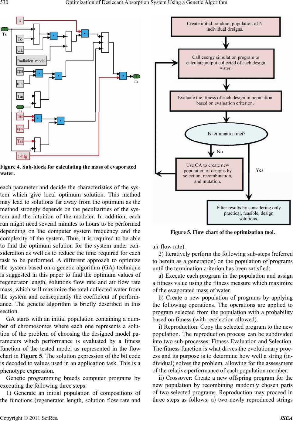
Here the goal is to find sets of system parameters that
will give a minimum fitness value over the operating
period [0, t]. The GA initializes a random set of popula-
tion of these three vari ab l es (regener at or l en gt h, solutions
flow rate and air flow rate mass).
Main system calculation parameters are presented in
Table 2. It should be noted that, moderate values of the
ambient parameters (temperature and humidity) are se-
lected for simulation purposes. However, variation of the
desiccant initial concentration may affect the value of the
system coefficient of performance (COP) but the opti-
mum design parameters will be the same values obtained
at the specified concentration which is used in the opti-
mization process.
Table 1. Specification of the GA.
Table 2. Calculation parameters of the syste m.
Ambient temperature, ˚C 33
Ambient vapor pressure, mm Hg 20
Desiccant (CaCl2) initi al concentration, % 40
Radiation intensity, kW/m2 0.8
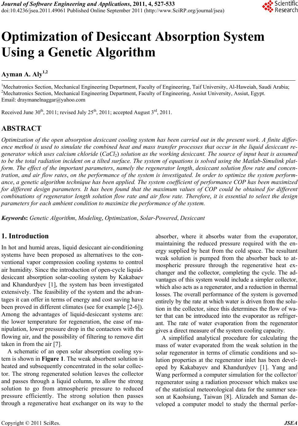
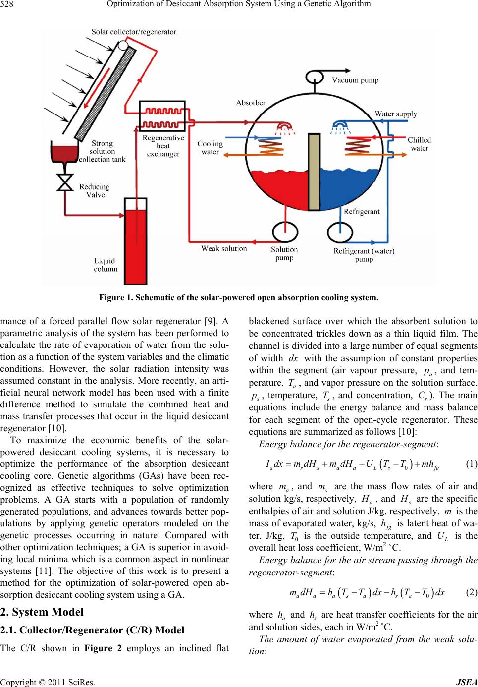
3. Results and Discussion
The performance of the solar collector/regenerator is
influenced by design parameters (regenerator length,
solution fl ow rate, working sol ution concentra t i o n and air
flow rate) and ambient conditions (air temperature and
vapor pressure in the flowing air). These key parameters
are investigated in the following sub-section s. A sensitiv-
ity analysis is performed by varying the parameters of
interest one at a time, while keeping all others fixed at
given values.
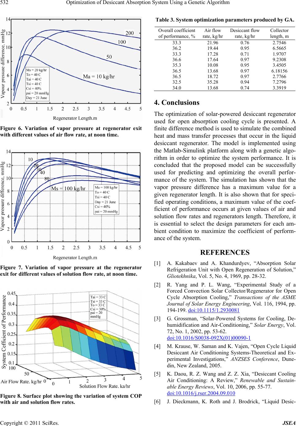
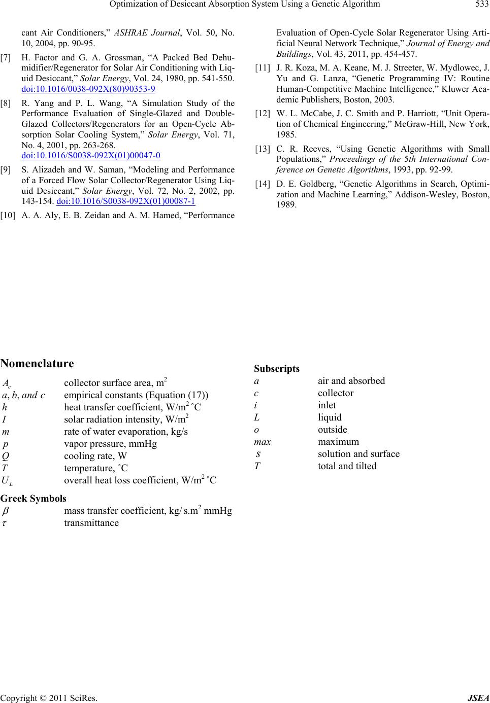
In order to analyze the effect of air mass flow rate on
the regeneration process, the solution mass flow rate,
s
m, is settled at 20 kg/hr and the range of air mass flow
rate, a, is considered in the range (10 kg/hr - 200
kg/hr), then the vapour pressure difference between the
regenerated solution and flowing air is plotted versus the
regenerator length. For a given regenerator length, the
vapour pressure, which is the mass transfer potential, is
directly proportional with the rate of water evaporation,
when the mass transfer coefficient is assumed constant.
As shown in Figures 6 and 7, the vapor pressure differ-
ence has a maximum for a given length of the regenera-
tor. The length, at which the maximum rate of evapora-
tion occurs, increases with the air flow rate. Concerning
the effect of solution inlet concentration on regeneration
process, the decrease of solution concentration can effec-
tively improve the regenerator performance, though it
sacrifices solution outlet concentration.
m
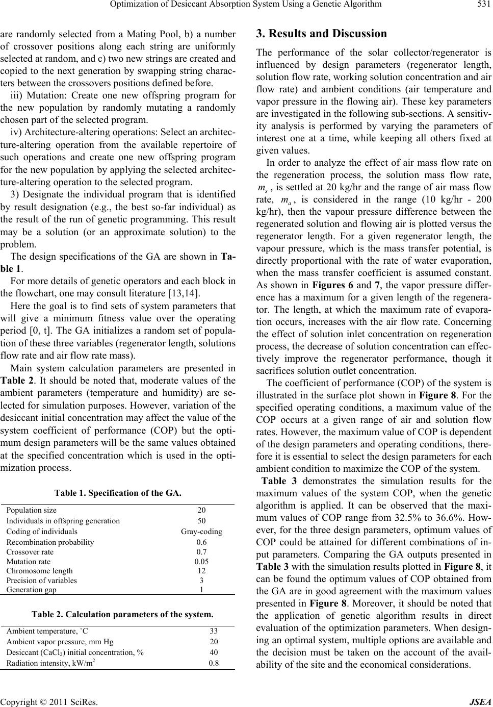
The coefficient of performance (COP) of the system is
illustrated in the surface plot shown in Figure 8. For the
specified operating conditions, a maximum value of the
COP occurs at a given range of air and solution flow
rates. However, the maximum value of COP is dependent
of the design parameters and operating conditions, there-
fore it is essential to select the design parameters for each
ambient condition to maximize the COP of the system.
Table 3 demonstrates the simulation results for the
maximum values of the system COP, when the genetic
algorithm is applied. It can be observed that the maxi-
mum values of COP range from 32.5% to 36.6%. How-
ever, for the three design parameters, optimum values of
COP could be attained for different combinations of in-
put parameters. Comparing the GA outputs presented in
Table 3 with the simulation results p lotted in Figure 8, it
can be found the optimum values of COP obtained from
the GA are in good agreement with the maximum values
presented in Figure 8. Moreover, it should be noted that
the application of genetic algorithm results in direct
evaluation of the optimization parameters. When design-
ing an o ptimal system, multiple options are available and
the decision must be taken on the account of the avail-
ability of the site and the economical considerations.
Population size 20
Individuals in offspring genera t i o n 50
Coding of individ uals Gray-coding
Recombination probability 0.6
Crossover rate 0.7
Mutation rate 0.05
Chromosom e len gth 12
Precision of variables 3
Generation gap 1
Copyright © 2011 SciRes. JSEA
Optimization of Desiccant Absorption System Using a Genetic Algorithm
532
Figure 6. Variation of vapor pressure at regenerator exit
with different values of air flow rate, at noon time.
Figure 7. Variation of vapor pressure at the regenerator
exit for different values of solution flow rate, at noon time.
Figure 8. Surface plot showing the variation of system COP
with air and solution flow rates.
Table 3. System optimization parameters produced by GA.
4. Conclusions
The optimization of solar-powered desiccant regenerator
used for open absorption cooling cycle is presented. A
finite difference method is u sed to simulate the combined
heat and mass transfer processes that occur in the liquid
desiccant regenerator. The model is implemented using
the Matlab-Simulink platform along with a genetic algo-
rithm in order to optimize the system performance. It is
concluded that the proposed model can be successfully
used for predicting and optimizing the overall perfor-
mance of the system. The simulation has shown that the
vapor pressure difference has a maximum value for a
given regenerator length. It is also shown that for speci-
fied operating conditions, a maximum value of the coef-
ficient of performance occurs at given values of air and
solution flow rates and regenerators length. Therefore, it
is essential to select the design parameters for each am-
bient condition to maximize the coefficient of perform-
ance of the system.
REFERENCES
[1] A. Kakabaev and A. Khandurdyev, “Absorption Solar
Refrigeration Unit with Open Regeneration of Solution,”
Gliotekhnika, Vol. 5, No. 4, 1969, pp. 28-32.
[2] R. Yang and P. L. Wang, “Experimental Study of a
Forced Convection Solar Collector/Regenerator for Open
Cycle Absorption Cooling,” Transactions of the ASME
Journal of Solar Energy Engineering, Vol. 116, 1994, pp.
194-199. doi:10.1115/1.2930081
[3] G. Grossman, “Solar-Powered Systems for Cooling, De-
humidification and Air-Conditioning,” Solar Energy, Vol.
72, No. 1, 2002, pp. 53-62.
doi:10.1016/S0038-092X(01)00090-1
[4] M. Krause, W. Saman a nd K. Vajen, “Open Cycle Liquid
Desiccant Air Conditioning Systems-Theoretical and Ex-
perimental Investigations,” ANZSES Conference, Dune-
din, New Zealand, 2005.
[5] K. Daou, R. Z. Wang and Z. Z. Xia, “Desiccant Cooling
Air Conditioning: A Review,” Renewable and Sustain-
able Energy Reviews , Vol. 10, 2006, pp. 55-77.
doi:10.1016/j.rser.2004.09.010
[6] J. Dieckmann, K. Roth and J. Brodrick, “Liquid Desic-
Overall coefficient
of perform ance, %Air flow
rate, kg/hrDesiccant flow
rate, kg/hr Collector
length, m
33.3 21.96 0.76 2.7546
36.2 19.44 0.95 6.5665
33.3 17.28 0.71 1.9707
36.6 17.64 0.97 9.2308
35.3 10.08 0.95 3.4505
36.5 13.68 0.97 6.18156
36.5 18.72 0.97 2.7766
32.5 35.28 0.94 7.2796
34.0 13.68 0.74 3.3919
Copyright © 2011 SciRes. JSEA
Optimization of Desiccant Absorption System Using a Genetic Algorithm
Copyright © 2011 SciRes. JSEA
533
cant Air Conditioners,” ASHRAE Journal, Vol. 50, No.
10, 2004, pp. 90-95.
[7] H. Factor and G. A. Grossman, “A Packed Bed Dehu-
midifier/Regenerator for Solar Air Conditioning with Liq-
uid Desiccant,” Solar Energy, Vol. 24, 1980, pp. 541-550.
doi:10.1016/0038-092X(80)90353-9
[8] R. Yang and P. L. Wang, “A Simulation Study of the
Performance Evaluation of Single-Glazed and Double-
Glazed Collectors/Regenerators for an Open-Cycle Ab-
sorption Solar Cooling System,” Solar Energy, Vol. 71,
No. 4, 2001, pp. 263-268.
doi:10.1016/S0038-092X(01)00047-0
[9] S. Alizadeh and W. Saman, “Modeling and Performance
of a Forced Flow Solar Collector/Regenerator Using Liq-
uid Desiccant,” Solar Energy, Vol. 72, No. 2, 2002, pp.
143-154. doi:10.1016/S0038-092X(01)00087-1
[10] A. A. Aly, E. B. Zeidan and A. M. Hamed, “Performance
Evaluation of Open-Cycle Solar Regenerator Using Arti-
ficial Neural Network Technique,” Journal of Energy and
Buildings, Vol. 43, 2011, pp. 454-457.
[11] J. R. Koza, M. A. Keane, M. J. Streeter, W. Mydlowec, J.
Yu and G. Lanza, “Genetic Programming IV: Routine
Human-Competitive Machine Intelligence,” Kluwer Aca-
demic Publishers, Boston, 2003.
[12] W. L. McCabe, J. C. Smith and P. Harriott, “Unit Opera-
tion of Chemical Engineering,” McGraw-Hill, New York,
1985.
[13] C. R. Reeves, “Using Genetic Algorithms with Small
Populations,” Proceedings of the 5th International Con-
ference on Genetic Algorithms, 1993, pp. 92-99.
[14] D. E. Goldberg, “Genetic Algorithms in Search, Optimi-
zation and Machine Learning,” Addison-Wesley, Boston,
1989.
Nomenclature Subscripts
a air and absorbed
c
A
collector surface area, m2 c collector
,,andc
h
ab empirical constants (Equation (17)) i inlet
heat transfer coefficient, W/m2 ˚C L liquid
I
solar radiation intensity, W/m2 o outside
m rate of water evaporation, kg/s max maximum
p vapor pressure, mmHg s solution and surface
Q cooling rate, W T total and tilted
T temperature, ˚C
L
U overall heat loss coefficient, W/m2 ˚C
Greek Symbols
mass transfer coefficient, kg/ s.m2 mmHg
transmittance