Energy and Power En gi neering, 2011, 3, 574-579
doi:10.4236/epe.2011.34071 Published Online September 2011 (http://www.SciRP.org/journal/epe)
Copyright © 2011 SciRes. EPE
The Effect of Retrofit Technologies on Formaldehyde
Emissions from a Large Bore Natural Gas Engine
Daniel B. Olsen*, Bryan D. Willson
Engines & Energy Conversion Laboratory, Department of Mechanical Engineering,
Colorado State University, Fort Collins, Colorado, USA
E-mail: *daniel.olsen@colostate.edu
Received June 23, 2011; revised July 28, 2011; accepted August 10, 2011
Abstract
Formaldehyde is an air toxic that is typically emitted from natural gas-fired internal combustion engines as a
product of incomplete combustion. The United States Environmental Protection Agency (EPA) regulates air
toxic emissions, including formaldehyde, from stationary reciprocating internal combustion engines. Na-
tional air toxic standards are required under the 1990 Clean Air Act Amendments. This work investigates the
effect that hardware modifications, or retrofit technologies, have on formaldehyde emissions from a large
bore natural gas engine. The test engine is a Cooper-Bessemer GMV-4TF two stroke cycle engine with a 14”
(35.6 cm) bore and a 14” (35.6 cm) stroke. The impact of modifications to the fuel injection and ignition
systems are investigated. Data analysis and discussion is performed with reference to possible formaldehyde
formation mechanisms and in-cylinder phenomena. The results show that high pressure fuel injection (HPFI)
and precombustion chamber (PCC) ignition significantly reduce formaldehyde emissions.
Keywords: Formaldehyde, Natural Gas, Fuel Injection, Precombustion Chamber, Large Bore
1. Introduction
Formaldehyde is a toxic emission that is specifically trou-
blesome for natural gas engines because it is a primary
combustion intermediate. It falls into a regulated group of
pollutants called HAPs (Hazardous Air Pollutants). HAPs
do not include criteria pollutants, carbon monoxide (CO),
oxides of nitrogen (NOX), or total hydrocarbons (THC).
They include a variety of aldehydes, volatile organic com-
pounds, semi-volatile organic compounds, sulfur com-
pounds, and metals. The United States Environmental Pro-
tection Agency (EPA) issues toxic regulations for oil and
gas production, as declared by the 1990 Clean Air Act
Amendments. It has been well established that the only
HAP present in the exhaust of large bore natural gas en-
gines in quantities of current regulatory significance is
formaldehyde [1]. The implications of air toxic regulations
to large bore natural gas engines used in gas compression
and power generation are well documented [2-4].
The mechanisms of formation for CO, NOX, and THC
have been studied extensively for a wide range of engine
designs and fuels. In contrast, relatively little is known
about the mechanisms through which engine-out formal-
dehyde is formed. Research in this area is in its infancy
relative to that of criteria pollutants. A thorough under-
standing of formaldehyde formation will be beneficial as
the natural gas industry responds to EPA air toxic regula-
tions and future revisions to these regulations.
This work addresses the dependency of stack formalde-
hyde emissions from a large bore natural gas engine on
hardware modifications. The level of insight into in-cylin-
der emissions formation mechanisms one can obtain from
stack emissions measurements is limited. However, it is
still useful and instructive to analyze the results, particu-
larly in the context of proposed engine-out formaldehyde
formation mechanisms. Based on earlier work by the au-
thors and co-workers [5,6] the following formaldehyde
formation mechani sms m ay be important:
1) Formaldehyde produced during piston and end-gas
compression and protected from flame propagation in re-
gions such as crevice volumes and wall quench zones
emerges during expansion.
2) Unburned hydrocarbons emitted during expansion
from regions protected from flame propagation are subse-
quently oxidized to formaldehyde.
3) Flame is quenched due to a cold wall, mixing with
cooler gas, or volume expansion; combustion reactions are
frozen and significant quantities of combustion intermedi-
D. B. OLSEN ET AL.575
ates, including formaldehyde, are produced.
2. Experimental Equipment and Conditions
2.1. Engine Testbed
The test engine is a Cooper-Bessemer GMV-4TF. A pho-
tograph of the engine is shown in Fi gure 1 . The GM V-4TF
is a 4 cylinder two-stroke cycle, 14” (35.6 cm) bore, 14”
(35.6 cm) stroke, natural gas fired engine. The GMV-4TF
has a sea level brake power rating of 440 bhp (330 kW) at
300 rpm. The GMV-4TF nominally uses electro-hydraulic
gas admission valves, which deliver fuel to each cylinder
individually at an injection pressure of about 45 psig (310
kPag). Actuation is performed by pressurized hydraulic
fluid on the back of the poppet valve stem. The pressurized
hydraulic fluid is controlled electronically by a solenoid
valve. The engine is nominally operated with single strike
spark ignition.
A combustion analysis system with piezoelectric pres-
sure transducers uses cylinder pressure profiles to calculate
peak pressure, location of peak pressure, misfire frequency,
and combustion stability parameters. A computer con-
trolled water brake dynamometer is employed for precise
load control. A turbocharger simulation system controls
intake and exhaust manifold pressures, allowing the simu-
lation of a wide range of engi ne “breat hing” configurati ons.
The turbocharger simulation system is composed of two
main components, a super charger (Roots blower) to pres-
surize the intake air and a motorized, computer controlled
backpressure valve. The facility also has the ability to con-
trol jacket water temperature, air manifold temperature, and
air manifold relative humidity. A Rosemount five-gas ana-
lyzer is used for measuring NOX, CO, THC, O2, and CO2,
and a Nicolet Fourier Transform Infrared (FTIR) Spec-
trometer for examination of a wide range of species in-
cluding formaldehyde, acetaldehy de, and acrolein.
Figure 1. The cooper bessemer GMV-4TF large bore natural
gas engine.
Table 1. Nominal operating conditions for the GMV-4TF.
HPFI and PCC technologies impact mixing and combustion
in the cylinder.
ENGINE
PARAMETER NOMINAL VALUE OR
SPECIFICA ION
Brake Power 440 hp (330 kW)
Dynamometer Torque 7730 ft-lb (10.5 kN-m)
Engine Speed 300 rpm (5 Hz)
Igniti on Tim i ng 10˚ BTDC
Intake Ma ni fold Pr es sure 7.5” Hg ( 25 k Pag)
Engine Pressure Drop 2.5” Hg (8.5 kPa)
Overall A/F Ratio 43
Trappe d A/F Rati o 22
Average Peak Pressure 505 psia (3.48 MPa)
Intake Manifold Temperature110˚ (317 K)
Intake Humidity Ratio 0.028 kg H2O/kg dry air
Jacket Water Temperature 160˚ (340 K)
Igniti on Single Str ike, Spar k
Fuel Delivery Direct Injection, Electro-hydraulic,
45 psig (310 kPag)
Variations in engine operating parameters and changes
to engine hardware configuration is performed relative to
the nominal operating conditions and hardware configura-
tion. The nominal operating conditions and hardware con-
figuration are summarized in Table 1.
2.2. Retrofit Technology
Retrofit technologies employed in this study are high pres-
sure fuel injection (HPFI), multi-strike (MS) ignition, and
precombustion chamber (PCC) ignition. The HPFI system
is produced by Woodward Governor and Dresser-Rand
Enginuity. The PCC is made by Diesel Supply Company.
The multi-strike (MS) ignition system is made by Altronic
Inc. Turbocharging is another retrofit technology that in-
creases the trapped air/fuel ratio. The effect of trapped
air/fuel ratio on formaldehyde emissions was evaluated in
previous work [7]. Turbocharging is generally imple-
mented to r educe NOX emissions by increasing the trapped
air/fuel ratio. Unfortunately, this significantly increases
emissions of formaldehyde and other products of partial
combustion.
In both cases mixing and combustion is enhanced by a
gas jet that flows into the cylinder and creates turbulence.
In HPFI (512 psia/3.5 MPa) an over-expanded gas fuel jet
enters the cylinder as a high energy density sonic jet. The
specific hardware configuration is described in other work
Copyright © 2011 SciRes. EPE
D. B. OLSEN ET AL.
576
[8,9]. After exiting the nozzle the jet subsequently expands
to supersonic velocities, followed by a barrel shock and
other compressible flow structures [10]. There are two
mechanisms by which combustion characteristics are al-
tered, enhanced mixing and increased turbulence. They can
impact combustion in different ways that are not easily
separated.
Data for three different fuel injection poppet valves
are presented in this paper. The geometries of these
valves are described in elsewhere [11]. The fuel injection
pressures for the low pressure mechanical, low pressure
electro-hydraulic, and high pressure electro-hydraulic are
25, 45, and 500 psig (0.17, 0.31, and 3.4 MPag), respec-
tively. Besides the difference in injection pressure, another
important difference between the valves is the lift profile.
The low pressure mechanica l valve is cam actuated and the
profile resembles a half sinusoid. The electro-hydraulically
actuated valves have lift profiles that approximate square
waves. The injection pressure for the high pressure elec-
tro-hydraulic valve is more than an order of magnitude
greater than th e low pressure mechanic al and low pressure
electro- hydraulic valves, which increases the fuel jet en-
ergy density (kinetic energy per unit volume) as the gas
enters the cylinder.
The fuel jet energy per unit volume at the valve exit is
plotted in Figure 2 for the three different valves, and thr ee
different high pressure electro-hydraulic cases. These cal-
culations are made with standa rd compressible flow analy-
sis assuming isentropic flow and applying a loss coefficient.
The jet exit kinetic energy per unit volume is approxi-
mately 10X higher for the 0.64 mm lift 3.4 MPag high
pressure electro-hydraulic case than for the low pressure
electro-hydraulic and low pressure mechanical cases. The
gas does not enter the cylinder at a higher speed because it
is choked at the exit in all cases, with the exception of the
last part of the low pressure mechanical valve injection
Figure 2. Fuel jet exit kinetic energy per unit volume at valve
exit plane.
when cylinder pressure is rising. However, the density of
the jet entering the cylinder is much higher for the high
pressure electro-mechanical case. The frontal area of the
exiting jet for the 0.64 mm lift 3.4 MPag high pressure
electro-hydraulic case is approximately 1/12th that of the
low pressure mechanical case. The dramatic increase in
fuel jet kinetic energy per unit volume enhances fuel and
air mixing and may increase the level of turbulence in the
cylinder during combustion. It is difficult to determine
whether the turbulence induced by fuel injection is present
during combustion, since combustion occurs later in the
cycle. Turbulence and mixing are two different, interrelated
effects that can affect combustion in different ways. It is
also possible that the acoustics in the cylinder play an im-
portant role. With a pressure ratio exceeding 34/1, strong
shock waves are generated when the high pressure valve is
actuated. These shock waves and their reflected shock
waves have gas displacements associated with them that
could enhance mixing as well.
In PCC ignition a stoichiometric or rich A/F mixture is
ignited with a spark plug in the PCC. A screw-in PCC is
utilized in this work. The hardware and operational details
are described elsewhere [12,13]. After ignition and pres-
sure rise in the PCC a jet of b urning fuel and air enters the
cylinder, providing a distributed ignition source and simul-
taneously creating turbulence and enhancing mixing. En-
hanced mixing, a distributed ignition source, and ignition
sources that be gin as turbulent flames, as opposed to spark
ignition where the combustion is initiated as a laminar
flame, simultaneously augment combustion.
3. Test Results
Figure 3 shows brake specific formaldehyde emissions vs.
boost, or air manifold pressure, for three different fuel in-
jectors. Data for the low pressure mechanical valve and
low pressure electro-hydraulic valve are relatively close
together. However, a significant decrease in formaldehyde
emissions is observed for the high pressure electro-hy-
draulic valve data at every boost level, with the exception
of the low boost point. The decrease in formaldehyde is
attributed to an increase in the mixing of fuel and air, or
charge homogeneity, in the cylinder. It is likely that the
increase in mixing decreases the level of incomplete com-
bustion in the cylinder, particularly in quench zones
(Mechanism #3 discussed above). Given this mechanism,
the anticipated parallel effect would be the simultaneous
reduction in THC emissions, since they too are ‘formed’ in
quench zones for lean combustion.
Figure 4 shows the expected decrease in THC emissions
for the high pressure electro-hydraulic valve. The THC
trends are very similar those observed in the formaldehyde
data, except there is a significant difference between the
Copyright © 2011 SciRes. EPE
D. B. OLSEN ET AL.577
0.12
0.14
0.16
0.18
0.2
0.22
0.24
5 6 7 8 91011121314151617
B o o s t ("H g )
B.S. CH2O (g/bhp-hr)
High Pressure, Electro-hydraulic
Low Pressure, Electro-hydraulic
Low Pressure, Mechanical
Figure 3. Formaldehyde emissions vs. boost for three different
fuel injection valves.
2
3
4
5
6
7
8
9
10
5678910 11 12 13 14 15 16 17
B o o s t (" H g)
B.S. THC (g/bhp-hr)
High Pressure, Electro-hydraulic
Low Pressure, Electro-hydraulic
Low Pressure, Mechanical
Figure 4. THC emissions vs. boost for three different fuel in-
jection valves.
low pressure electro-hydraulic valve and the mechanical
valve. This highlights an advantage of the low pressure
electro-hydraulic valve. Other emissi ons, CO and NOX (not
shown), also change with the implementation of high pres-
sure electro-hydraulic injection. Emissions of CO are high-
er for high pressure electro-hydraulic for the same boost. It
is interesting that CO and formaldehyde are both products
of partial combustion, though high pressure shifts them in
opposite directions. It indicates that formation mechanisms
for formaldehyde and CO are different. Emissions of NOX
are reduced with HPFI for the same boost. This is primarily
due a reduction in fuel consumption for HPFI, resulting in
a leaner air fuel ratio. NOX emission is generally reduced at
leaner air fuel ratios due to lower in-cylinder temperatures.
Figures 5 and 6 plot Brake Specific Fuel Consumption
(BSFC) and Coefficient of Variation (COV) of Peak Pres-
sure (PP) vs. Boost. The fuel consumption reduction is
evident. High pressure electro-hydraulic reduces fuel
shown) are also reduced by PCC ignition. However,the
reduction occurs primarily at high boost >12” Hg. con-
sumption at all boost levels compared to low pressure me-
chanical and at most boost levels compared to low pressure
electro-hydraulic. COV of PP is a measure of combustion
instability. High pressure electro-hydraulic produces lower
Figure 5. Brake specific fuel consumption vs. boost for three
different fuel valves.
Figure 6. COV PP vs. Boos t for three different fu el valves.
combustion instability (Figure 6) than the other two cases
at most boost levels. This is due to improved mixing.
Lower COV of PP represents an extension of lean limit of
combustion, which allows additional NOX reductions to be
realized.
Figure 7 shows how formaldehyde emissions change
with various ignition sources, including a PCC. For most of
the boost levels tested, the PCC shows a significant de-
crease in formaldehyde emissions. The difference between
SS and MS is insignificant. In general enhanced ignition
sources tend to stabilize combustion, reducing combustion
variability. Although the PCC is characterized by a burning
jet flowing into the main chamber, the impact on mixing is
expected to be less than HPFI because the timing of PCC
ignition is later in the cycle. The benefit of PCC on for-
maldehyde formation is likely due to the impact on com-
bustion stability. The frequency of quenching due to partial
combustion is reduced when combustion is stabili zed.
The impact of PCC ignition on combustion stability is
shown in Figure 8. The data shows a dramatic decrease in
Copyright © 2011 SciRes. EPE
D. B. OLSEN ET AL.
578
Figure 7. Formaldehyde emissions vs. Boost for three different
ignition sources with low pressure electro-hydraulic fuel
valves.
Figure 8. COV of Peak Pressure vs. Boost for three different
ignition sources with low pressure electro-hydraulic fuel
valves.
COV PP (increase in combustion stability) for PCC igni-
tion. The COV of PP for a given boost is approximately
reduced by half. THC emissions and brake specific fuel
consumption (not shown) are also reduced by PCC ignition.
However, the reduction occurs primarily at high boost >
12” Hg.
4. Discussion
The data shows that HPFI and PCC ignition reduce for-
maldehyde significantly for the same engine operating pa-
rameters (speed, torque, and boost). These hardware
changes physically impact mixing and combustion in such
a way to reduce formaldehyde formation. The observed
reductions in formaldehyde support mechanisms 1, 2, and 3
discussed in the Introducti on. Reducti on i n formaldehyde is
typically accompanied by a reduction in THC emissions.
Three different modes are identified for formaldehyde re-
duction that can be related to HPFI and/or PCC ignition.
They are described below.
The first mode of formaldehyde reduction is related to
the reduction of the number of fuel rich regions in quench
zones, such as crevice volumes. This mode is tied closely
to HPFI. If the spread rate of the fuel jet is large enough
fuel could flow directly into the top land crevice volume
between the piston and cylinder, above the top ring. Previ-
ous visualization work using Planar Laser Induced Fluo-
rescence (PLIF) [11,14] showed that the low pressure jet
spreads and impinges directly on the top land crevice
volume. Consequently fuel is forced into the top land
crevice volume, creating a protected rich zone. However,
the high pressure jet is narrow and impinges on the cen-
ter of the piston with high velocity, creating a large scale
motion that directs fuel upward and away from the top
land crevice volume. HPFI tends to promote a uniform
charge throughout the cylinder. This reduces THC emis-
sions by eliminating regions of high fuel concentration.
However, even with a homogeneous charge fuel resides
in crevice regions characterized by the average trapped
A/F ratio. Many crevice regions have dimensions smaller
than typical flame quench distances, so the flame is un-
able to propagate into the crevice and consume the resi-
dent fuel. This fuel can exit the crevice during expansion
and be oxidized to fo rmaldehyde.
The second mode of formaldehyde reduction involves
turbulence that is present throughout the combustion proc-
ess. The turbulence could be residual turbulence from high
pressure injection or PCC jet induced turbulence. As com-
bustion occurs in the cylinder, turbulence scavenges the
unburned fuel and formaldehyde in the crevice volumes
and mixes it with hot combustion gases, burning to com-
pletion.
The third mode of formaldehyde reduction involves
more effective ignition. More effective ignition reduces
partial combustion and misfire. A more uniform charge,
created by HPFI, can be more reliably ignited since there
are fewer regions outside the flammability range of the fuel.
A distributed ignition source induced by the PCC jet
achieves more reliable ignition in the lean main chamber
because it is spatially distributed across the cylinder. It is
not localized like a spark plug. Reduction of partial com-
bustion through more reliable ignition reduces the impact
of bulk quenching during expansion where formaldehyde
can be formed.
5. Conclusions
The two techniques investigated as ways to augment mix-
ing and combustion are HPFI and PCC ignition. Both are
shown to be highly effective at reducing formaldehyde.
Maximum reductions of about 15% are realized in both
cases. HPFI improves mixing of fuel and air in the cylinder.
This reduces fuel trapped in crevice volumes, creates a
more homogeneous mixture, and stabilizes combustion.
Copyright © 2011 SciRes. EPE
D. B. OLSEN ET AL.
Copyright © 2011 SciRes. EPE
579
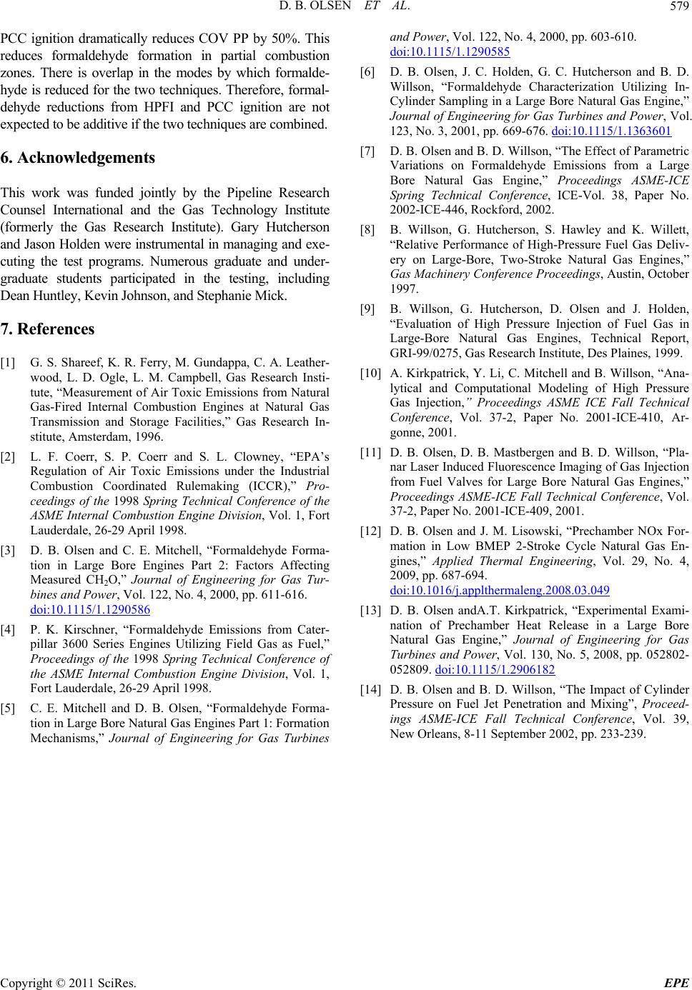
PCC ignition dramatically reduces COV PP by 50%. This
reduces formaldehyde formation in partial combustion
zones. There is overlap in the modes by which formalde-
hyde is reduced for the two techniques. Therefore, formal-
dehyde reductions from HPFI and PCC ignition are not
expected to be additive i f the two techniques are com bined.
6. Acknowledgements
This work was funded jointly by the Pipeline Research
Counsel International and the Gas Technology Institute
(formerly the Gas Research Institute). Gary Hutcherson
and Jason Holden were instrumental in managing and exe-
cuting the test programs. Numerous graduate and under-
graduate students participated in the testing, including
Dean Huntley, Kevin Johnson, and Stephanie Mick.
7. References
[1] G. S. Shareef, K. R. Ferry, M. Gundappa, C. A. Leather-
wood, L. D. Ogle, L. M. Campbell, Gas Research Insti-
tute, “Measurement of Air Toxic Emissions from Natural
Gas-Fired Internal Combustion Engines at Natural Gas
Transmission and Storage Facilities,” Gas Research In-
stitute, Amsterdam, 1996.
[2] L. F. Coerr, S. P. Coerr and S. L. Clowney, “EPA’s
Regulation of Air Toxic Emissions under the Industrial
Combustion Coordinated Rulemaking (ICCR),” Pro-
ceedings of the 1998 Spring Technical Conference of the
ASME Internal Combustion Engine Division, Vol. 1, Fort
Lauderdale, 26-29 April 1998.
[3] D. B. Olsen and C. E. Mitchell, “Formaldehyde Forma-
tion in Large Bore Engines Part 2: Factors Affecting
Measured CH2O,” Journal of Engineering for Gas Tur-
bines and Power, Vol. 122, No. 4, 2000, pp. 611-616.
doi:10.1115/1.1290586
[4] P. K. Kirschner, “Formaldehyde Emissions from Cater-
pillar 3600 Series Engines Utilizing Field Gas as Fuel,”
Proceedings of the 1998 Spring Technical Conference of
the ASME Internal Combustion Engine Division, Vol. 1,
Fort Lauderdale, 26-29 April 1998.
[5] C. E. Mitchell and D. B. Olsen, “Formaldehyde Forma-
tion in Large Bore Natural Gas Engines Part 1: Formation
Mechanisms,” Journal of Engineering for Gas Turbines
and Power, Vol. 122, No. 4, 2000, pp. 603-610.
doi:10.1115/1.1290585
[6] D. B. Olsen, J. C. Holden, G. C. Hutcherson and B. D.
Willson, “Formaldehyde Characterization Utilizing In-
Cylinder Sampling in a Large Bore Natural Gas Engine,”
Journal of Engineering for Gas Turbines and Power, Vol.
123, No. 3, 2001, pp. 669-676. doi:10.1115/1.1363601
[7] D. B. Olsen and B. D. Willson, “The Effect of Parametric
Variations on Formaldehyde Emissions from a Large
Bore Natural Gas Engine,” Proceedings ASME-ICE
Spring Technical Conference, ICE-Vol. 38, Paper No.
2002-ICE-446, Rockford, 2 0 02 .
[8] B. Willson, G. Hutcherson, S. Hawley and K. Willett,
“Relative Performance of High-Pressure Fuel Gas Deliv-
ery on Large-Bore, Two-Stroke Natural Gas Engines,”
Gas Machinery Conference Proceedings, Austin, October
1997.
[9] B. Willson, G. Hutcherson, D. Olsen and J. Holden,
“Evaluation of High Pressure Injection of Fuel Gas in
Large-Bore Natural Gas Engines, Technical Report,
GRI-99/0275, Gas Research Institute, Des Plaines, 1999.
[10] A. Kirkpatrick, Y. Li, C. Mitchell and B. Willson, “Ana-
lytical and Computational Modeling of High Pressure
Gas Injection,” Proceedings ASME ICE Fall Technical
Conference, Vol. 37-2, Paper No. 2001-ICE-410, Ar-
gonne, 2001.
[11] D. B. Olsen, D. B. Mastbergen and B. D. Willson, “Pla-
nar Laser Induced Fluorescence Imaging of Gas Injection
from Fuel Valves for Large Bore Natural Gas Engines,”
Proceedings ASME-ICE Fall Technical Conference, Vol.
37-2, Paper No. 2001-ICE-409, 2001.
[12] D. B. Olsen and J. M. Lisowski, “Prechamber NOx For-
mation in Low BMEP 2-Stroke Cycle Natural Gas En-
gines,” Applied Thermal Engineering, Vol. 29, No. 4,
2009, pp. 687-694.
doi:10.1016/j.applthermaleng.2008.03.049
[13] D. B. Olsen andA.T. Kirkpatrick, “Experimental Exami-
nation of Prechamber Heat Release in a Large Bore
Natural Gas Engine,” Journal of Engineering for Gas
Turbines and Power, Vol. 130, No. 5, 2008, pp. 052802-
052809. doi:10.1115/1.2906182
[14] D. B. Olsen and B. D. Willson, “The Impact of Cylinder
Pressure on Fuel Jet Penetration and Mixing”, Proceed-
ings ASME-ICE Fall Technical Conference, Vol. 39,
New Orleans, 8-11 September 2002, pp. 233-239.