A. ABBASI ET AL.481
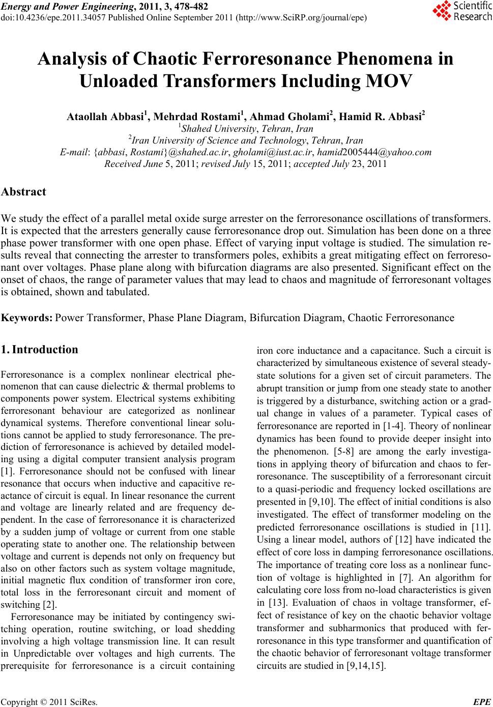
Figure 8. Bifurcation diagram for q = 5 with MOV.
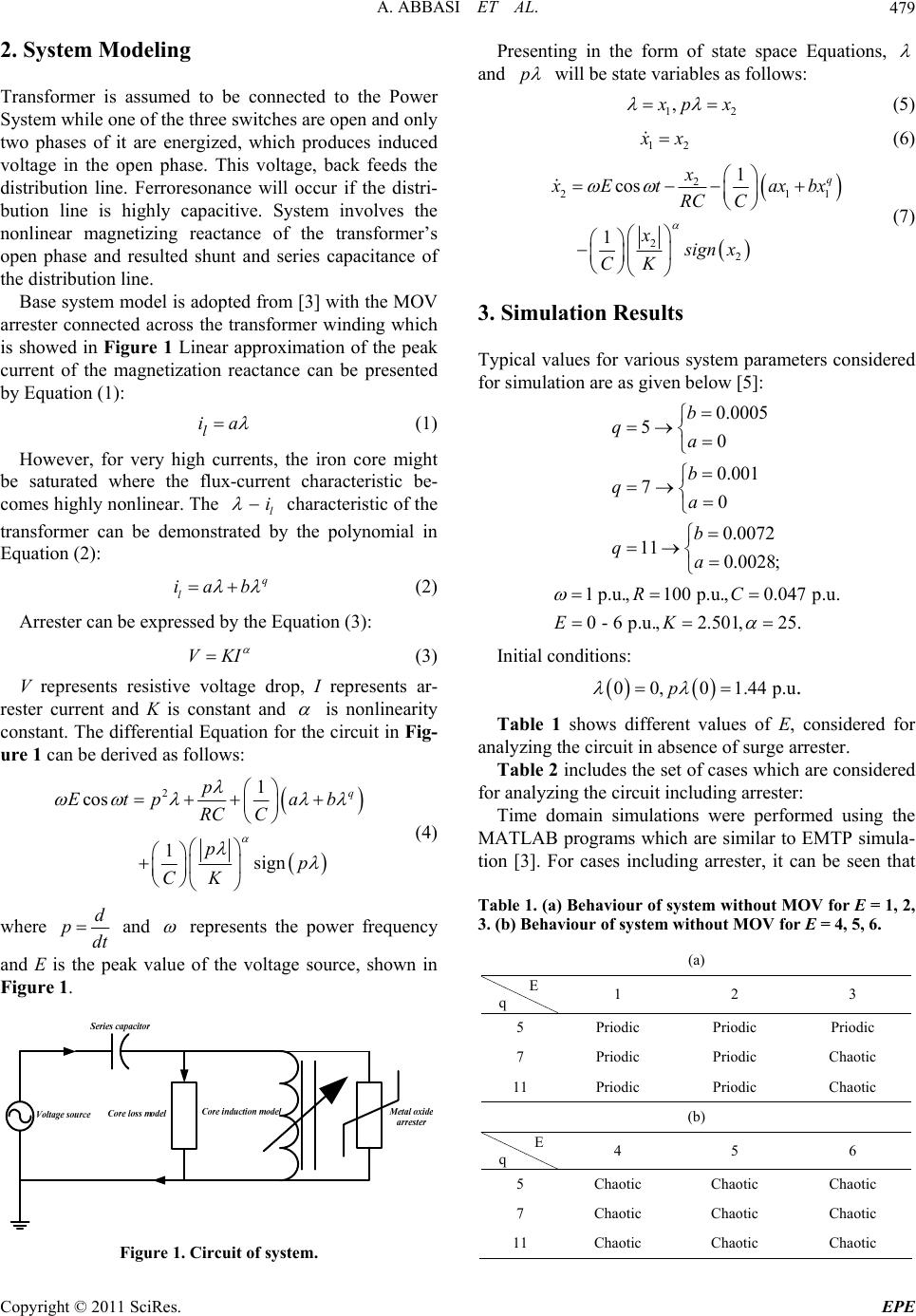
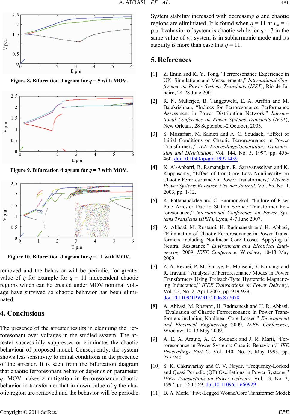
Figure 9. Bifurcation diagram for q = 7 with MOV.
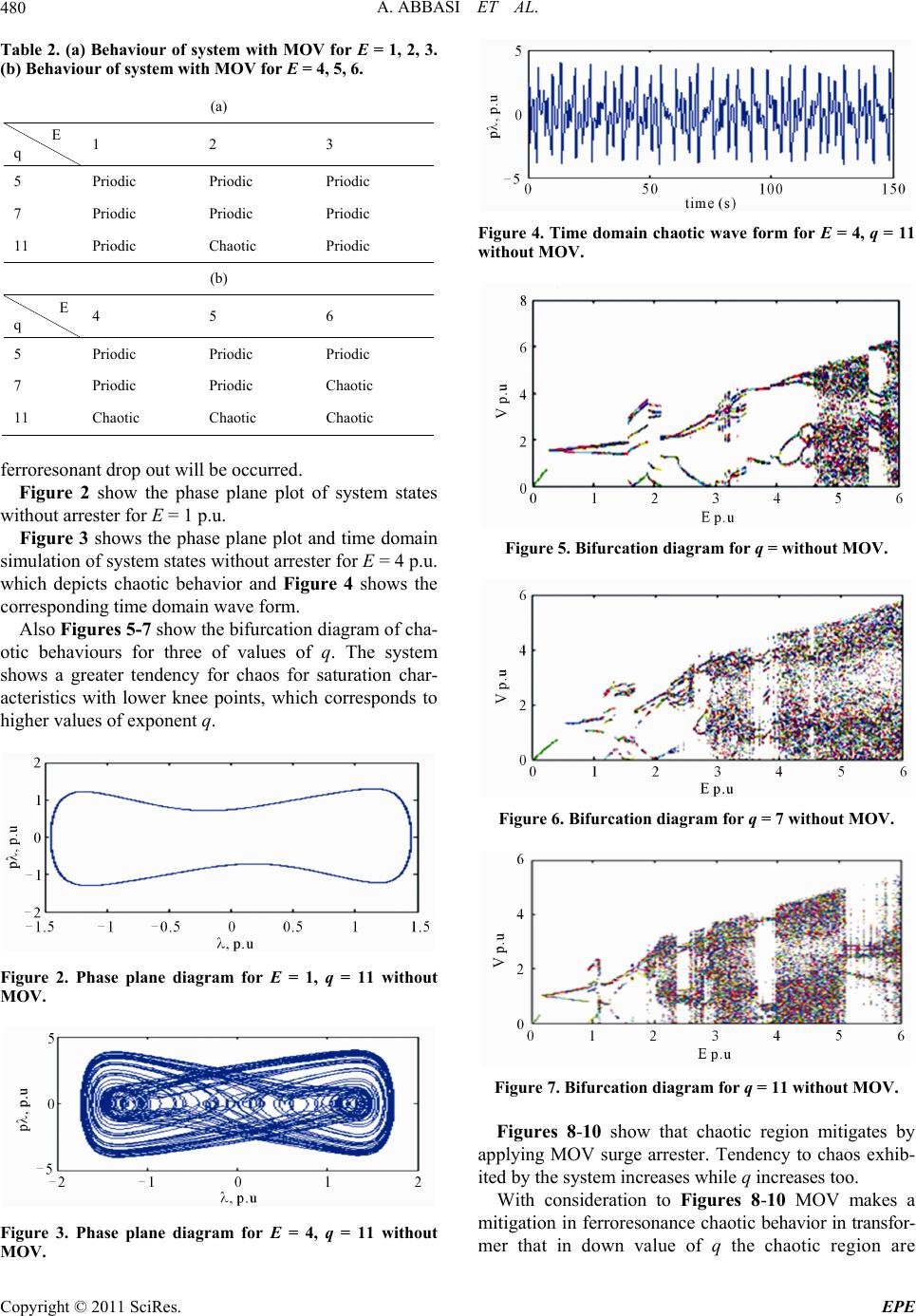
Figure 10. Bifurcation diagram for q = 11 with MOV.
removed and the behavior will be periodic, for greater
value of q for example for q = 11 independent chaotic
regions which can be created under MOV nominal volt-
age have survived so chaotic behavior has been elimi-
nated.
4. Conclusions
The presence of the arrester results in clamping the Fer-
roresonant over voltages in the studied system. The ar-
rester successfully suppresses or eliminates the chaotic
behaviour of proposed model. Consequently, the system
shows less sensitivity to initi al conditions in th e presence
of the arrester. It is seen from the bifurcation diagram
that chaotic ferroresonant behavior depends on parameter
q. MOV makes a mitigation in ferroresonance chaotic
behavior in transformer that in down value of q the cha-
otic region are removed and the behavior will be periodic.
System stability increased with decreasing q and chaotic
regions are eliminiated. It is found when q = 11 at vin = 4
p.u. beahavior of system is chaotic while for q = 7 in the
same value of vin system is in subharmonic mode and its
stability is more than case that q = 11.
5. References
[1] Z. Emin and K. Y. Tong, “Ferroresonance Experience in
UK: Simulations and Measurements,” International Con-
ference on Power Systems Transients (IPST), Rio de Ja-
neiro, 24-28 June 2001.
[2] R. N. Mukerjee, B. Tanggawelu, E. A. Ariffin and M.
Balakrishnan, “Indices for Ferroresonance Performance
Assessment in Power Distribution Network,” Interna-
tional Conference on Power Systems Transients (IPST),
New Orleans, 28 September-2 October, 2003.
[3] S. Mozaffari, M. Sameti and A. C. Soudack, “Effect of
Initial Conditions on Chaotic Ferroresonance in Power
Transformers,” IEE Proceedings/Generation, Transmis-
sion and Distribution, Vol. 144, No. 5, 1997, pp. 456-
460. doi:10.1049/ip-gtd:19971459
[4] K. Al-Anbarri, R. Ramanujam, R. Saravanaselvan and K.
Kuppusamy, “Effect of Iron Core Loss Nonlinearity on
Chaotic Ferroresonance in Power Transformers,” Electric
Power Systems Research Elsevier Journal, Vol. 65, No. 1,
2003, pp. 1-12.
[5] K. Pattanapakdee and C. Banmongkol, “Failure of Riser
Pole Arrester Due to Station Service Transformer Fer-
roresonance,” International Conference on Power Sys-
tems Transients (IPST), Lyon, 4-7 June 2007.
[6] A. Abbasi, M. Rostami, H. Radmanesh and H. Abbasi,
“Elimination of Chaotic Ferroresonance in Power Trans-
formers Including Nonlinear Core Losses Applying of
Neutral Resistance,” Environment and Electrical Engi-
neering 2009, IEEE Conference, Wroclaw, 10-13 May
2009.
[7] Z. A. Rezaei, P. M. Sanay e, H. Mohseni, S. Farhangi an d
R. Iravani, “Analysis of Ferroresonance Modes in Power
Transformers Using Preisach-Type Hysteretic Magnetiz-
ing Inductance,” IEEE Transactions on Power Delivery,
Vol. 22, No. 2, April 2007, pp. 919-929.
doi:10.1109/TPWRD.2006.877078
[8] A. Abbasi, M. Rostami, H. Radmanesh and H. R. Abbasi,
“Evaluation of Chaotic Ferroresonance in Power Trans-
formers including Nonlinear Core Losses,” Environment
and Electrical Engineering 2009, IEEE Conference,
Wroclaw, 10-13 May 2009..
[9] A. E. A. Araujo, A. C. Soudack and J. R. Marti, “Fer-
roresonance in Power Systems: Chaotic Behaviour,” IEE
Proceedings Part C, Vol. 140, No. 3, May 1993, pp.
237-240.
[10] S. K. Chkravarthy and C. V. Nayar, “Frequency-Locked
and Quasi Periodic (QP) Oscillations in Power Systems,”
IEEE Transactions on Power Delivery, Vol. 13, No. 2,
1997, pp. 560-569. doi:10.1109/61.660929
[11] B. A. Mork, “Five-Legged Wound/Core Transformer Model:
Copyright © 2011 SciRes. EPE