Energy and Power En gi neering, 2011, 3, 401-406
doi:10.4236/epe.2011.34051 Published Online September 2011 (http://www.SciRP.org/journal/epe)
Copyright © 2011 SciRes. EPE
Study of Sliding Mode Control of Dc-Dc Buck Converter
Hanifi Guldemir
Technical Education Fa culty, University of Firat, Elazig, Turkey
E-mail: hguldemir@firat.edu.tr
Received January 23, 2011; revised March 2, 2011; accepted March 15, 2011
Abstract
In this paper, a robust sliding mode controller for the control of dc-dc buck converter is designed and ana-
lyzed. Dynamic equations describing the buck converter are derived and sliding mode controller is designed.
A two-loop control is employed for a buck converter. The robustness of the sliding mode controlled buck
converter system is tested for step load changes and input voltage variations. The theoretical predictions are
validated by means of simulations. Matlab/Simulink is used for the simulations. The simulation results are
presented. The buck converter is tested with operating point changes and parameter uncertainties. Fast dy-
namic response of the output voltage and robustness to load and input voltage variations are obtained.
Keywords: Switched-Mode Power Supplies, Buck Converter, Dc-Dc Converter, Sliding Mode Control
1. Introduction
Electronic power converters are used as an actuator for
electromechanical systems. The buck type dc-dc converters
are used in applications where the required output voltage
is lower than the source voltage. Different control algo-
rithms are applied to regulate dc-dc converters to achieve a
robust output voltage. As dc-dc converters are nonlinear
and time variant systems, the application of linear control
techniques for the control of these converters are not suit-
able. In order to design a linear control system using clas-
sical linear control techniques, the small signal model is
derived by linearization around a precise operating point
from the state space average model [1]. The controllers
based on these techniques are simple to implement how-
ever, it is difficult to account the variation of system pa-
rameters, because of the dependence of small signal model
parameters on the converter operating point [2]. Variations
of system parameters and large signal transients such as
those produced in the start up or against changes in the load,
cannot be dealt with these techniques. Multiloop control
techniques, such as current mode control, have greatly im-
proved the dynamic behavior, but the control design re-
mains difficult especially for higher order converter to-
pologies [3].
A control technique suitable for dc-dc converters must
cope with their intrinsic nonlinearity and wide input volt-
age and load variations, ensuring stability in any operating
condition while providing fast transient response. Since
switching converters constitute a case of variable structure
systems, the sliding mode control technique can be a possi-
ble option to control this kind of circuits [4]. The use of
sliding mode control enables to improve and even over-
come the deficiency of the control method based on small
signal models. In particular, sliding mode control improves
the dynamic behavior of the system, and becomes very
useful when the system is required to operate in the pres-
ence of significant unknown disturbances and plant uncer-
tainties [5].
In order to obtain the desired response, the sliding mode
technique changes the structure of the controller in re-
sponse to the changing state of the system. This is realized
by the use of a high speed switching control forcing the
trajectory of the system to move to and stay in a predeter-
mined surface which is called sliding surface. The regime
of a control system in the sliding surface is called Sliding
Mode. In sliding mode a system’s response remains insen-
sitive to parameter variations and disturbances [6]. Unlike
other robust schemes, which are computationally intensive
linear methods, analogue implementations or digital com-
putation of sliding mode is simple.
2. The Mathematical Model of Dc-Dc Boost
Converter
The topology of a buck converter is shown in Figure 1.
When the switch is on position 1 the circuit is connected to
the dc input source resulting an output voltage across the
load resistor. If the switch changes its position to position 0,
the capacitor voltage will discharge through the load. Con-
H. GULDEMIR
402
L
C
E
i
L
i
C
+
-
R
Figure 1. The buck converter.
trolling switch position the output voltage can be main-
tained at a desired level lower than the input source volt-
age.
The buck converter shown in Figu re 1 can be described
by the following set of equations
d
d
Lo
i
LuEV
t
(1)
d
d
o
L
o
v
Ci
ti
(2)
where iL is the inductor current, Vo is the output capacitor
voltage, E is the constant external input voltage source, L is
the inductance, C is the capacitance of the output filter and
R is the output load resistance. u is the control input taking
discrete values of 0 and 1 which represents the switch posi-
tion.
0 if switch is at position 0
1 if switch is at position 1
u
(3)
It is assumed here that the inductor current will have a
nonzero value due to load variations which is known as the
continuous conduction mode (CCM). Figure 2 shows the
current and voltage in continuous conduction mode.
Rewriting Equations (1) and (2) in the form of state
equations by taking the inductor current and output capaci-
L
CREV
o
i
L
V
L
+-
Figure 2. Topology of buck converter and current.
tor voltage as the states of the system, the following state
equations are obtained.
d
d
o
LV
iEu
tL L

(4)
d
d
o
L
V
iu
tC RC

o
V
(5)
where
0
o
V
iR
(6)
The block diagram of the buck converter using state
Equations (4) and (5) is shown in Figure 3.
3. Sliding Mode Control
The sliding mode provides a method to design a system in
such a way that the controlled system is to be insensitive
to parameter variations and external load disturbances
[7-10]. The technique consists of two modes. One is the
reaching mode in which the trajectory moves towards the
sliding line from any initial point. In reaching mode, the
system response is sensitive to parameter uncertainties
and disturbances. The other is the sliding mode in which,
the state trajectory moves to origin along the switching
line and the states never leave the switching line. During
this mode, the system is defined by the equation of the
switching surface and thus it is independent of the system
parameters.
The Variable Structure System (VSS) theory has been
applied to nonlinear systems [11]. One of the main fea-
tures of this method is that one only needs to drive the
error to a switching surface, after which the system is in
sliding mode and robust against modeling uncertainties
and disturbances. A Sliding Mode Controller includes
several different continuous functions that map plant state
to a control surface, and the switching among different
functions is determined by plant state that is represented
dt
di
L
dt
dv
s
1
s
1
Figure 3. Block diagram of a buck converter.
Copyright © 2011 SciRes. EPE
H. GULDEMIR403
by a switching function. The theory of the sliding mode
applied dc-dc converters and other areas can be found in
references [12-15] and will not be given here. The main
aim is to force the system states to the sliding surface, and
the adopted control strategy must guarantee the system
trajectory move toward and stay on the sliding surface
from any initial condition as in Figure 4.
4. Sliding Mode Controller Design
In sliding mode, the control is discontinuous in nature.
Here, the control switches at an infinite speed between
two different structures. A sliding mode control system
may be regarded as a combination of subsystems, each
with a fixed structure and operating in a particular region
of the state space. The sliding mode control design prob-
lem is to select parameters for each of the structure and
define a switching logic.
Using the state equations given in Equations (1) and (2)
and letting x1 = iL and x2 = V as the new states of the sys-
tem, the new state equations become
1
1E
2
x
ux
LL

(7)
21 2
11
x
x
CRC

x (8)
Generally, the control for dc-dc converters is to regu-
late the output voltage at desired level. Now the aim here
is to obtain a desired constant output voltage Vd. The
desired output is then x1
* = Vd/R. The task is to ensure the
actual current x1 tracks the desired current. That is, in
steady state the output voltage should be the desired
voltage Vd. Thus,
2d
x
V (9)
20
d
xV
(10)
Sliding mode controller uses a sliding surface which
ensures output voltage to go to desired value once the
x
x
x(0)
reaching
mode
sliding
mode
switching
line
.
Figure 4. The modes of variable structure control systems.
system gets onto the sliding surface. The state variables
may be used to construct the sliding function. From the
general sliding mode control theory, the state variable
error, defined by difference to the reference value, forms
the sliding function
*
11
0Sxx

(11)
This means that the control forces the system to evolve
on the sliding surface [2]. The reference value x1
* is de-
rived internally to the controller from the output of the
linear voltage controller.
In order to enforce sliding mode in the manifold S = 0,
the corresponding control signal for the ideal switch in
Figure 1 is [12]

11
2
usign
S
(12)
Since the aim is to guarantee that the state trajectory of
the system is directed to the sliding surface S = 0 and
slides over it, this is achieved with a suitable design of
control law using the reaching condition
0SS
(13)
since
*
11
Sxx

(14)
The steady state values of state variables coincide with
the corresponding reference values and they are con-
stants then, replacing Equation (11) in Equation (13) and
solving it we get
2
0
x
E
(15)
This means that the sliding mode exists if the output
voltage is lower than the source voltage.
5. Simulations
In order to obtain a desired output voltage, the closed-
loop control is then necessary to maintain the output
voltage even the input voltage has some variation. The
analysis of the converter shows that the system dynamics
can be divided into fast (current) and slow (voltage) mo-
tion. In this study two-loop control, an inner current con-
trol loop and an outer voltage control loop, is used. The
voltage loop controller is a linear PI type with parameters
of Kp = 50 and KI = 10 controller. Since the motion rate
of the current is much faster than that of the output volt-
age, a sliding mode controller is used in the inner current
loop. A closed-loop control system for buck converter is
designed and the block diagram of the overall system is
shown in Figure 5.
Simulations were performed on a typical “buck” con-
verter circuit with the following parameter values: E = 20
V, L = 40 mH, C = 4 F, R = 40 (Table 1).
Copyright © 2011 SciRes. EPE
H. GULDEMIR
404
IL. V
O
BUCK
Step 1
PID
SMC
E
Load
Loa
d
E
IL
V
O
u
u
s
+
+
Figure 5. Simulink block of the closed loop control of buck
converter.
Table 1. Converter parameters.
E (V) L (mH) C (F) R ()
20 40 4 40
Figure 6 shows output voltage and current transient
response during a change in the reference voltage from
10 V to 12 V at time t = 0.005 s.
Generally speaking, sliding mode control is regarded
as a robust feedback control technique with respect to
matched unmodelled external perturbation signals and
plant parameter variations.
In order to test the robustness of the sliding mode con-
trol scheme, the load resistor R has been let undergo a
sudden unmodelled and permanent variation of 50% of
its nominal value of 40 . This variation took place, ap-
proximately, at time, t = 0.003 s, while the system was
already stabilized to the desired voltage value of 10 V
and, it takes the value of 25 , at t = 0.006 s.
Figure 7 shows the excellent recovering features of
the proposed controller to the imposed load variation. As
expected, the output voltage is robust when the load re-
sistance was subject to a sudden unmodelled variation
from R = 40 to R = 60 at time t = 0.003 s, and from
R = 60 to R = 25 at time t = 0.006 s.
Figure 8 shows the performance of the sliding mode
based control scheme, when the input voltage E is
changed from 20 V to 22 V at the time t = 0.003 s and
from 22 V to 18 V at t = 0.006 s, with a desired steady
state output voltage of 10 V.
Figure 7 and 8 allows to prove the robustness of the
sliding mode control against changes in the load and
variations in the input voltage.
The phase portrait can be seen in Figure 9 when ref-
erence voltage is 15 V and the load is 60 . The control-
ler makes the trajectory to form a stable limit cycle. The
limit cycle width on the Vo-axis is equal to the voltage
ripple seen on the output of the converter. In Figure 9,
phase portrait is given.
The two phases of the dynamics can easily be ob-
served in the figure. The states first reach the sliding
surface and then are constrained to the sliding surface.
Instead of sliding, the states fluctuate around the sliding
surface. When the states reach to a close neighborhood
00.002 0.004 0.006 0.0080.01
0
2
4
6
8
10
12
14
t (s)
Vo (Volt)
V
o
(Volt)
00.002 0.004 0.006 0.0080.01
0
0. 05
0. 1
0. 15
0. 2
0. 25
0. 3
0. 35
t (s)
I (A)
Figure 6. Output voltage and input current waveforms for
step change in reference voltage.
00.002 0.004 0.006 0.0080.01
0
2
4
6
8
10
12
20
40
60
80
100
R

R
Vo (Volt)
t (s)
V
o
(Volt)
00.002 0.004 0.0060.0080.01
0
0. 1
0. 2
0. 3
0. 4
0. 5
t (s)
I (A)
Figure 7. Output voltage and input current waveforms for
step load variations.
Copyright © 2011 SciRes. EPE
H. GULDEMIR405
00.002 0.004 0.006 0.008 0.01
0
t (s)
Vo (Volt)
2
4
6
8
10
12
4
8
12
16
20
24
E
E (V o lt)
V
o
(Volt)
00.002 0.004 0.006 0.0080.01
0
0.05
0.1
0.15
0.2
0.25
0.3
0.35
t (s)
I
(A)
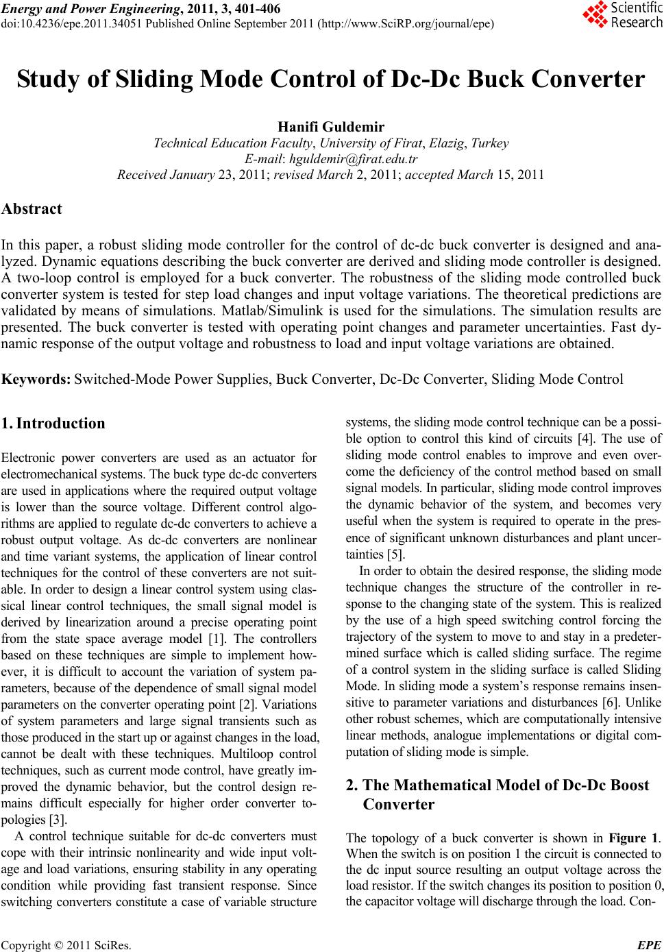
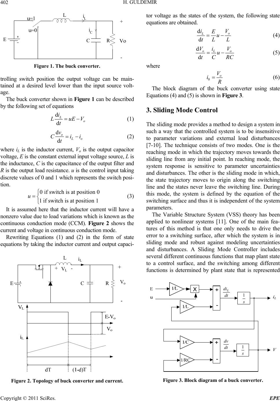
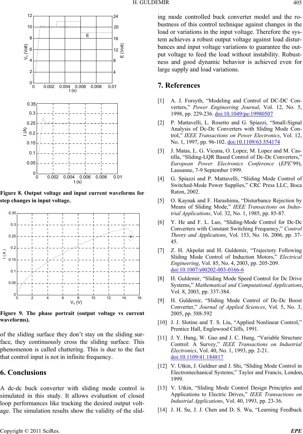
Figure 8. Output voltage and input current waveforms for
step changes in input voltage.
02 46 810 1214 16
0
0.05
0. 1
0.15
0. 2
0.25
0. 3
0.35
Vo ( V )
I ( A )
V
o
(V)
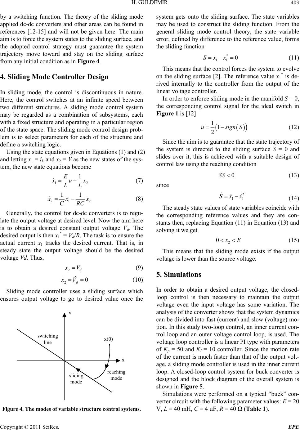
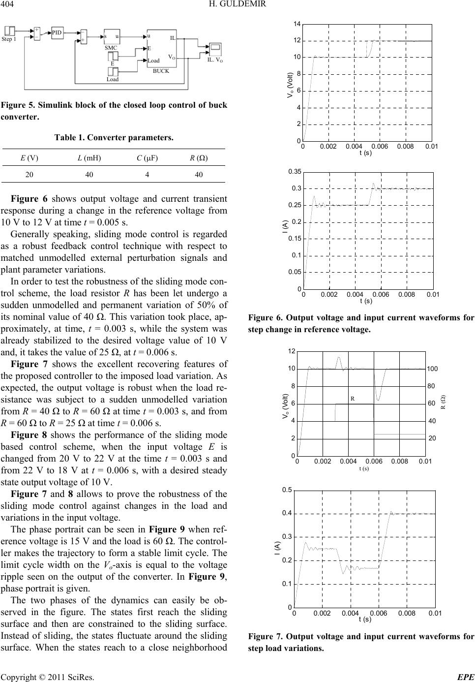
Figure 9. The phase portrait (output voltage vs current
waveforms).
of the sliding surface they don’t stay on the sliding sur-
face, they continuously cross the sliding surface. This
phenomenon is called chattering. This is due to the fact
that control input is not in infinite frequency.
6. Conclusions
A dc-dc buck converter with sliding mode control is
simulated in this study. It allows evaluation of closed
loop performances like tracking the desired output volt-
age. The simulation results show the validity of the slid-
ing mode controlled buck converter model and the ro-
bustness of this control technique against changes in the
load or variations in the input voltage. Therefore the sys-
tem achieves a robust output voltage against load distur-
bances and input voltage variations to guarantee the out-
put voltage to feed the load without instability. Robust-
ness and good dynamic behavior is achieved even for
large supply and load variations.
7. References
[1] A. J. Forsyth, “Modeling and Control of DC-DC Con-
verters,” Power Engineering Journal, Vol. 12, No. 5,
1998, pp. 229-236. doi:10.1049/pe:19980507
[2] P. Mattavelli, L. Rosetto and G. Spiazzi, “Small-Signal
Analysis of Dc-Dc Converters with Sliding Mode Con-
trol,” IEEE Transactions on Power Electronics, Vol. 12,
No. 1, 1997, pp. 96-102. doi:10.1109/63.554174
[3] J. Matas, L. G. Vicuna, O. Lopez, M. Lopez and M. Cas-
tilla, “Sliding-LQR Based Control of Dc-Dc Converters,”
European Power Electronics Conference (EPE’99),
Lausanne, 7-9 September 1999.
[4] G. Spiazzi and P. Mattavelli, “Sliding Mode Control of
Switched-Mode Power Supplies,” CRC Press LLC, Boca
Raton, 2002.
[5] O. Kaynak and F. Harashima, “Disturbance Rejection by
Means of Sliding Mode,” IEEE Transactions on Indus-
trial Applications, Vol. 32, No. 1, 1985, pp. 85-87.
[6] Y. He and F. L. Luo, “Sliding-Mode Control for Dc-Dc
Converters with Constant Switching Frequency,” Control
Theory and Applications, Vol. 153, No. 16, 2006, pp. 37-
45.
[7] Z. H. Akpolat and H. Guldemir, “Trajectory Following
Sliding Mode Control of Induction Motors,” Electrical
Engineering, Vol. 85, No. 4, 2003, pp. 205-209.
doi:10.1007/s00202-003-0166-6
[8] H. Guldemir, “Sliding Mode Speed Control for Dc Drive
Systems,” Mathematical and Computational Applications,
Vol. 8, 2003, pp. 337-384.
[9] H. Guldemir, “Sliding Mode Control of Dc-Dc Boost
Converter,” Journal of Applied Sciences, Vol. 5, No. 3,
2005, pp. 588-592
[10] J. J. Slotine and T. S. Liu, “Applied Nonlinear Control,”
Prentice Hall, Englewood Cliffs, 1991.
[11] J. Y. Hung, W. Gao and J. C. Hung, “Variable Structure
Control: A Survey,” IEEE Transactions on Industrial
Electronics, Vol. 40, No. 1, 1993, pp. 2-21.
doi:10.1109/41.184817
[12] V. Utkin, J. Guldner and J. Shi, “Sliding Mode Control in
Electromechanical Systems,” Taylor and Francis, London,
1999.
[13] V. Utkin, “Sliding Mode Control Design Principles and
Applications to Electric Drives,” IEEE Transactions on
Industrial Applications, Vol. 40, 1993, pp. 23-36.
[14] J. H. Su, J. J. Chen and D. S. Wu, “Learning Feedback
Copyright © 2011 SciRes. EPE
H. GULDEMIR
Copyright © 2011 SciRes. EPE
406
Controller Design of Switching Converters via Matlab/
Simulink,” IEEE Transactions on Education, Vol. 45,
2002, pp. 307-315. doi:10.1109/TE.2002.803403
[15] H. Sira-Ramirez, “On the Generalized PI Sliding Mode
Control of DC to DC Power Converters: A Tutorial,” In-
ternational Journal of Control, Vol. 76, No. 9, 2003, pp.
1018-1033.