Paper Menu >>
Journal Menu >>
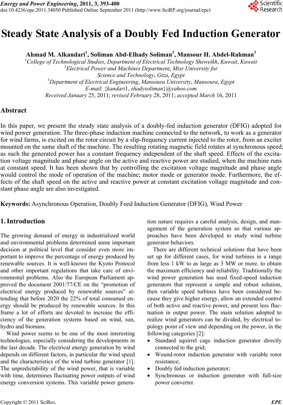 Energy and Power En gi neering, 2011, 3, 393-400 doi:10.4236/epe.2011.34050 Published Online September 2011 (http://www.SciRP.org/journal/epe) Copyright © 2011 SciRes. EPE Steady State Analysis of a Doubly Fed Induction Generator Ahmad M. Alkandari1, Soliman Abd-Elhady Soliman2, Mansour H. Abdel-Rahman3 1College of Technological Studies, Department of Electrical Technology Sheweikh, Kuwait, Kuwait 2Electrical Power and Machines Department, Misr University for Science and Technology, Giza, Egypt 3Department of Electrical Engineering, Mansoura University, Mansoura, Egypt E-mail: {kandari1, shadysoliman}@yahoo.com Received January 25, 2011; revised February 28, 2011; accepted March 16, 2011 Abstract In this paper, we present the steady state analysis of a doubly-fed induction generator (DFIG) adopted for wind power generation. The three-phase induction machine connected to the network, to work as a generator for wind farms, is excited on the rotor circuit by a slip-frequency current injected to the rotor, from an exciter mounted on the same shaft of the machine. The resulting rotating magnetic field rotates at synchronous speed; as such the generated power has a constant frequency independent of the shaft speed. Effects of the excita- tion voltage magnitude and phase angle on the active and reactive power are studied, when the machine runs at constant speed. It has been shown that by controlling the excitation voltage magnitude and phase angle would control the mode of operation of the machine; motor mode or generator mode. Furthermore, the ef- fects of the shaft speed on the active and reactive power at constant excitation voltage magnitude and con- stant phase angle are also investigated. Keywords: Asynchronous Operation, Doubly Feed Induction Generator (DFIG), Wind Power 1. Introduction The growing demand of energy in industrialized world and environmental problems determined some important decision at political level that consider even more im- portant to improve the percentage of energy produced by renewable sources. It is well-known the Kyoto Protocol and other important regulations that take care of envi- ronmental problems. Also the European Parliament ap- proved the document 2001/77/CE on the “promotion of electrical energy produced by renewable sources” at- tending that before 2020 the 22% of total consumed en- ergy should be produced by renewable sources. In this frame a lot of efforts are devoted to increase the effi- ciency of the generation systems based on wind, sun, hydro and biomass. Wind power seems to be one of the most interesting technologies, especially considering the developments in the last decade. The electrical energy generation by wind depends on different factors, in particular the wind speed and the characteristics of the wind turbine generator [1]. The unpredictability of the wind power, that is variable with time, determines fluctuating power outputs of wind energy conversion systems. This variable power genera- tion nature requires a careful analysis, design, and man- agement of the generation system so that various ap- proaches have been developed to study wind turbine generato r be haviors. There are different technical solutions that have been set up for different cases, for wind turbines in a range from less 1 kW to as large as 3 MW or more, to obtain the maximum efficiency and reliability. Traditionally the wind power generation has used fixed-speed induction generators that represent a simple and robust solution, then variable speed turbines have been considered be- cause they give higher energy, allow an extended control of both active and reactive power, and present less fluc- tuation in output power. The main solution adopted to realize wind generators can be divided, by electrical to- pology point of view and depending on the power, in the following categories [2]: Standard squirrel cage induction generator directly connected to the grid; Wound-rotor induction generator with variable rotor resistance; Doubly fed inductio n generator; Synchronous or induction generator with full-size power converter. 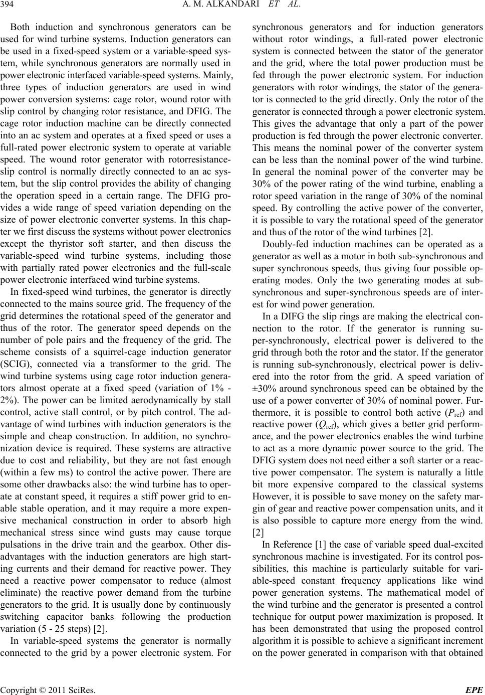 A. M. ALKANDARI ET AL. 394 Both induction and synchronous generators can be used for wind turbine systems. Induction generators can be used in a fixed-speed system or a variable-speed sys- tem, while synchronous generators are normally used in power electronic interfac ed variable-speed systems. Mainly, three types of induction generators are used in wind power conversion systems: cage rotor, wound rotor with slip control by changing rotor resistance, and DFIG. The cage rotor induction machine can be directly connected into an ac system and operates at a fixed speed or uses a full-rated power electronic system to operate at variable speed. The wound rotor generator with rotorresistance- slip control is normally directly connected to an ac sys- tem, but the slip control provides the ability of changing the operation speed in a certain range. The DFIG pro- vides a wide range of speed variation depending on the size of power electronic converter systems. In this chap- ter we first discuss the systems without power electronics except the thyristor soft starter, and then discuss the variable-speed wind turbine systems, including those with partially rated power electronics and the full-scale power electronic interfaced wind turbine systems. In fixed-speed wind turbines, the generator is directly connected to the mains source grid. The frequency of the grid determines the rotational speed of the generator and thus of the rotor. The generator speed depends on the number of pole pairs and the frequency of the grid. The scheme consists of a squirrel-cage induction generator (SCIG), connected via a transformer to the grid. The wind turbine systems using cage rotor induction genera- tors almost operate at a fixed speed (variation of 1% - 2%). The power can be limited aerodynamically by stall control, active stall control, or by pitch control. The ad- vantage of wind turbin es with induction generators is the simple and cheap construction. In addition, no synchro- nization device is required. These systems are attractive due to cost and reliability, but they are not fast enough (within a few ms) to control the active power. There are some other drawbacks also: the wind turbine has to oper- ate at constant speed, it requires a stiff power grid to en- able stable operation, and it may require a more expen- sive mechanical construction in order to absorb high mechanical stress since wind gusts may cause torque pulsations in the drive train and the gearbox. Other dis- advantages with the induction generators are high start- ing currents and their demand for reactive power. They need a reactive power compensator to reduce (almost eliminate) the reactive power demand from the turbine generators to the grid. It is usually done by continuously switching capacitor banks following the production variation (5 - 25 steps) [2]. In variable-speed systems the generator is normally connected to the grid by a power electronic system. For synchronous generators and for induction generators without rotor windings, a full-rated power electronic system is connected between the stator of the generator and the grid, where the total power production must be fed through the power electronic system. For induction generators with rotor windings, the stator of the genera- tor is connected to the grid directly. On ly the rotor of the generator is conn ected through a power electronic system. This gives the advantage that only a part of the power production is fed through the power electronic converter. This means the nominal power of the converter system can be less than the nominal power of the wind turbine. In general the nominal power of the converter may be 30% of the power rating of the wind turbine, enabling a rotor speed variation in the range of 30% of the nominal speed. By controlling the active power of the converter, it is possible to vary the rotational speed of the generator and thus of the rotor of the wind turb ines [2]. Doubly-fed induction machines can be operated as a generator as well as a motor in both sub-synchronous and super synchronous speeds, thus giving four possible op- erating modes. Only the two generating modes at sub- synchronous and super-synchronous speeds are of inter- est for wind power generation. In a DIFG the slip rings are making the electrical con- nection to the rotor. If the generator is running su- per-synchronously, electrical power is delivered to the grid through both the rotor an d th e stator. If the generator is running sub-synchronously, electrical power is deliv- ered into the rotor from the grid. A speed variation of ±30% around synchronous speed can be obtained by the use of a p ower converter of 30 % of nominal power. Fur- thermore, it is possible to control both active (Pref) and reactive power (Qref), which gives a better grid perform- ance, and the power electronics enables the wind turb ine to act as a more dynamic power source to the grid. The DFIG system does not need either a soft starter or a reac- tive power compensator. The system is naturally a little bit more expensive compared to the classical systems However, it is possible to save money on the safety mar- gin of gear and reactiv e power compensation units, and it is also possible to capture more energy from the wind. [2] In Reference [1] the case of variable speed dual- exc ited synchronous machine is inv estigated. For its control pos- sibilities, this machine is particularly suitable for vari- able-speed constant frequency applications like wind power generation systems. The mathematical model of the wind turbine and the generator is presented a control technique for output power maximization is proposed. It has been demonstrated that using the proposed control algorithm it is possible to achiev e a significant increment on the power generated in comparison with that obtained Copyright © 2011 SciRes. EPE 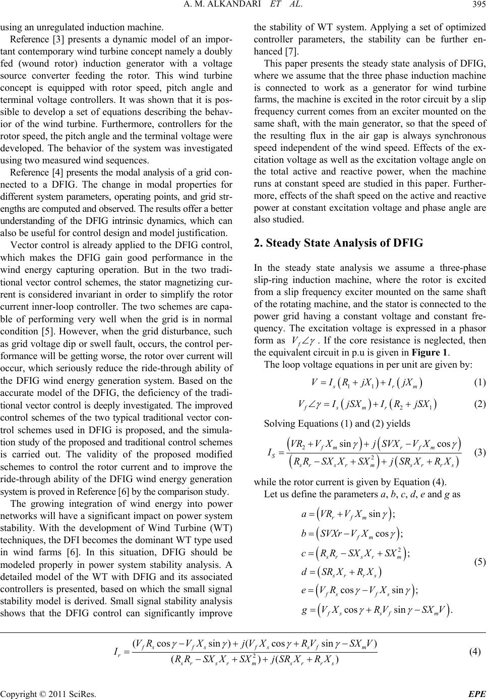 A. M. ALKANDARI ET AL. Copyright © 2011 SciRes. EPE 395 using an unregulated induction machine. the stability of WT system. Applying a set of optimized controller parameters, the stability can be further en- hanced [7]. Reference [3] presents a dynamic model of an impor- tant contemporary wind turbine concept namely a doubly fed (wound rotor) induction generator with a voltage source converter feeding the rotor. This wind turbine concept is equipped with rotor speed, pitch angle and terminal voltage controllers. It was shown that it is pos- sible to develop a set of equations describing the behav- ior of the wind turbine. Furthermore, controllers for the rotor speed, the pitch ang le and th e terminal vo ltag e were developed. The behavior of the system was investigated using two measured wind sequences. This paper presents the steady state analysis of DFIG, where w e assume that the three phase induction machine is connected to work as a generator for wind turbine farms, the machine is excited in the rotor circuit by a slip frequency current comes from an exciter moun ted on the same shaft, with the main generator, so that the speed of the resulting flux in the air gap is always synchronous speed independent of the wind speed. Effects of the ex- citation voltage as well as th e excitation vo ltage angle on the total active and reactive power, when the machine runs at constant speed are studied in this paper. Further- more, effects of the shaft speed on the active and reactive power at constant excitation voltage and phase angle are also studied. Reference [4] presents the modal analysis of a grid c on- nected to a DFIG. The change in modal properties for different system parameters, operating points, and grid str- engths are computed and observed. The results offer a better understanding of the DFIG intrinsic dynamics, which can also be useful for control design and model justification. 2. Steady State Analysis of DFIG Vector control is already applied to the DFIG control, which makes the DFIG gain good performance in the wind energy capturing operation. But in the two tradi- tional vector control schemes, the stator magnetizing cur- rent is considered invariant in order to simplify the rotor current inner-loop controller. The two schemes are capa- ble of performing very well when the grid is in normal condition [5]. However, when the grid disturbance, such as grid voltage dip or swell fault, occurs, the control per- formance will be getting wo rse, the rotor over current will occur, which seriously reduce the ride-through ability of the DFIG wind energy generation system. Based on the accurate model of the DFIG, the deficiency of the tradi- tional vector control is deeply investigated. The improved control schemes of the two typical traditional vector con- trol schemes used in DFIG is proposed, and the simula- tion study of the proposed and traditional control schemes is carried out. The validity of the proposed modified schemes to control the rotor current and to improve the ride-through ability of the DFIG wind energy generation system is proved in Reference [6] by the comparison study. In the steady state analysis we assume a three-phase slip-ring induction machine, where the rotor is excited from a slip frequency exciter mounted on the same shaft of the rotating machine, and the stator is connected to the power grid having a constant voltage and constant fre- quency. The excitation voltage is expressed in a phasor form as f V . If the core resistance is neglected, then the equivalent circuit in p.u is given in Figure 1. The loop voltage equations in per unit are given by: 11 s rm VIR jXIjX (1) 2fsmr VIjSXIRjSX 1 (2) Solving Equations (1) and (2) yields 2 2 sin cos fmr fm S srs rms rrs VRV XjSVXV X IRRSX XSXjSRXRX (3) while the rotor current is given by Equation (4). Let us define the parameters a, b, c, d, e and g as The growing integration of wind energy into power networks will have a significant impact on power syste m stability. With the development of Wind Turbine (WT) techniques, the DFI becomes the dominant WT type used in wind farms [6]. In this situation, DFIG should be modeled properly in power system stability analysis. A detailed model of the WT with DFIG and its associated controllers is presented, based on which the small signal stability model is derived. Small signal stability analysis shows that the DFIG control can significantly improve 2 sin ; cos ; ; cossin ; cos sin. rfm fm srs rm sr rs fsf s fs sfm aVRVX bSVXrVX cRRSXXSX dSRXRX eVR VX g VXRV SXV (5) 2 (cossin )(cossin) ()() fs fsfssfm r srs rms rr s VR VXjVXRVSXV IRRSX XSXjSRXRX (4)  A. M. ALKANDARI ET AL. 396 V R S j x s JX m j x r R r /S I S I r S f V Figure 1. Steady state equivalent circuit of DFIG referred to the stator. ator and rotor currents can be written as: Then the st s ajb Icjd r ej g Icjd (6) The active and reactive power of the stator can be ob- tained as: S (7) Substituting for * SVI PJQ * * Real Im SSS Ss SS PV I QVI S I then the active and reactive power of the stator is n by: give 22 S Vacad Pcd 22 S Vb c ad Qcd (8) Note that the stator active power is positive for m toring operation and is negative for generating operation an r o- d vice versa for the reactive power. The expressions for active and reactive power of the rotor (exciter) are given as: * rf SVI PJQ * * Real Im rr rfr rfr PV I QVI ( Substituting 9) r I into (9) we obtain 22 cos ff r Ve gdVcg P 22 si n sin cos ff r c ed cd Vecgd Vcged Qcd (10) Note that, if the excitation voltage f Vth equals zero, the machine performs in accordance with e basic oper- at tio of a doubly feed induction machine. teristics we assume d to an uit of the exciter is connected to the same source as such the output of the ge is applied to the machine rotor while the machine speed , i.e. varies from 1 to –1. The parameters of the machine ch .6 p. his is obviously correct, since the machines de of 0.6, the machine es the results ob tained for th e s tat or reactive ing characteristics similar to a convennal induction machine. Obviously, no power active or reactive is gen- erated. Equation (10) describes the steady state operation 3. Steady State Characteristics In studying the steady state charac that the stator of the main machine is connecte infinite bus source, and the primary circ exciter is a source of a slip frequency and injects power to the slip rings of the rotor of the main machine. As such the current in the stator of the main machine has a constant frequency independent of the shaft speed. 3.1. Effects of Excitation Voltage Magnitude In this study we assume a constant excitation volta changes from zero to double the synchronous speed S used in this study are given in Tables A.1 and A.2 [7]. Figure 2 gives the results obtained for the stator active power when the slip is changed from –1 to 1, i.e. speed anges to double the synchronous speed, while we changed the excitation voltage magnitude from 0 to 0 u in step of 0.2 p.u. Examining these curves reveals the following: At Vf =0, induction motor operation, the machine delivers power to the network, via the stator windings, at speed greater synchronous speed, slip greater than –0.05. T runs as an induction generator At excitation voltage magnitude of 0.2 and 0.4 p.u the machine delivers power to the source at this speed ranges. For excitation voltage magnitu delivers power to the source at sub-synchronous speed, speed less than synchronous speed. Figure 3 giv power versus the speed at a constant excitation voltage Figure 2. Stator active power versus speed at constant exci- tation voltage. Copyright © 2011 SciRes. EPE 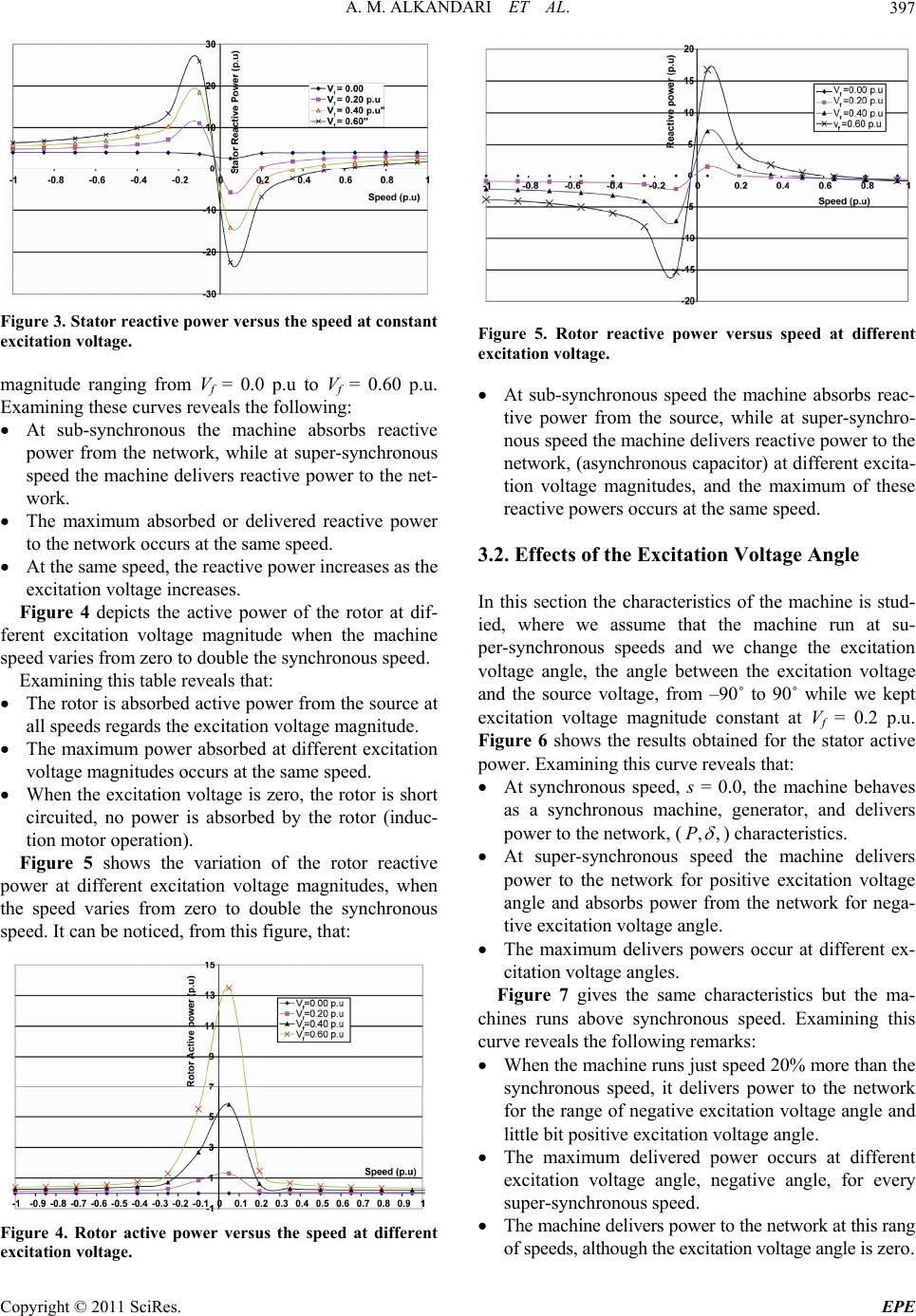 A. M. ALKANDARI ET AL.397 Figure 3. Stator reactive power versus the speed at constant excitation voltage. magnitude ranging from Vf = 0.0 p.u to Vf = 0.60 p.u. Examining these curves reveals the following: At sub-synchronous the machine absorbs reactive power from the network, while at super-synchronous speed the machine delivers reactive power to the net- work. The maximum absorbed or delivered reactive power to the network occurs at the same speed. At the same speed, the reactive power increases as the excitation voltage increases. Figure 4 depicts the active power of the rotor at di o to double the synchronous speed. Examining this table reveals that: d, no power is absorbed by the rotor (induc tor reactive ouble the synchronous sp f- ferent excitation voltage magnitude when the machine speed varies from zer The rotor is absorbed active power from the source at all speeds regards the excitation voltage magnitude. The maximum power absorbed at different excitation voltage magnitudes occurs at the same speed. When the excitation voltage is zero, the rotor is short circuite - tion motor operation). Figure 5 shows the variation of the ro power at different excitation voltage magnitudes, when the speed varies from zero to d eed. It can be noticed, from this figure, that: Figure 4. Rotor active power versus the speed at different excitation voltage. Figure 5. Rotor reactive power versus speed at different excitation voltage. At sub-synchronous speed the machine absorbs reac- tive power from the source, while at super-synchro- nous speed the machine delivers reactive power to the network, (asynchronous capacitor) at different excita- tion voltage magnitudes, and the maximum of these reactive powers occurs at the same speed. 3.2. Effects of the Excitation Voltage Angle In this section the characteristics of the machine is stud- ied, where we assume that the machine run at su angle between the excitation voltage nd the source voltage, from –90˚ to 90˚ while we kept - per-synchronous speeds and we change the excitation voltage angle, the a excitation voltage magnitude constant at Vf = 0.2 p.u. Figure 6 shows the results obtained for the stator active power. Examining this curve reveals that: At synchronous speed, s = 0.0, the machine behaves as a synchronous machine, generator, and delivers power to the network, (,,P ) characteristics. rs oltage angle and absorbs power from the network for nega- o the network ifferent on voltage angle is zero. At super-synchronous speed the machine delive power to the network for positive excitation v tive excitation voltage angle. The maximum delivers powers occur at different ex- citation voltage angles. Figure 7 gives the same characteristics but the ma- chines runs above synchronous speed. Examining this curve reveals the following remarks: When the machine runs just speed 20% more than the synchronous speed, it delivers power t for the range of negative excitation voltage angle and little bit positive excitation voltage angle. The maximum delivered power occurs at d excitation voltage angle, negative angle, for every super-synchronous speed. The machine delivers power to the network at this rang of speeds, although the excitati Copyright © 2011 SciRes. EPE  A. M. ALKANDARI ET AL. 398 -25 -20 -15 -10 Stator Power (p.u) -5 0 5 -90 -80 -70 -60 -50 -40 -30 -20 -100102030405060708090 Excitation Angle(Degree) 10 S-0.0 S=0.1 S=0.15 S=0.2 Figure 6. Stator power versus excitation angle at constant speed. -10 -8 -6 -4 -2 0 2 4 6 8 -90-80-70-60-50-40-30-20-10010 20 30 40 50 60 70 80 90 Excitation Angle Stator Power (p.u) S=-0.10 S=-0.15 S=-0.2 Figure 7. The stator power versus the excitation angle when the machine above synchronous spee d, Vf = 0.2 p.u. Figures 8 and 9 give the excitation power for sub- synchronous and super-synchronous speed operation, re- spectively, and the excitation voltage magnitude is kept constant at Vf = 0.2 p.u Examining these curves reveals the following conclu- sions: At synchronous speed, S = 0.0, the excitation power is constant regardless the magnitude of the excitation voltage angle. The excitation power having the same trend regard- less the speed of the machine, sup or super synchro negative excitation voltage angle and at sub-syn- give the stator reactive power va uns at sub-synchronous and super-synchronous t : haves as a non-salient pole syn chronous machin e and the - nous speed. The machine delivers power to the network at almost chronous and super-synchronous speed, respectively. The maximum positive or maximum negative powers occur at different excitation voltage angle. Figures 10 and 11 riation with the excitation voltage angle, when the ma- chine r speeds, respectively, while the excitation voltage magni- tude is kept constant at Vf = 0.20 p.u. Examining these figures reveals tha 1) At synchronous speed, S = 0.0, the machine be- -1 0 1 -90 -80 -70 -60-50 -40 -30 -20 -100102030405060708090 Excitation Angle(Degr e e ) 2 3 4 n Power (p.u) 5 Excitatio S=0.0 S=0.1 S=0.15 S=0.2 Figure 8. Excitation power versus excitation angle. -1 -0.5 0 0.5 1 1.5 -90 -80-70-60 -50 -40-30 -20 -100102030405060708090 Excitation Angle (degree) Exc itation P ower P 2 (p .u ) S=-0.10 S=-0.15 S=-0.20 Figure 9. Excitation power versus excitation angle when th mac e hine runs above synchronous speed, Vf = 0.2 p.u. -25 -20 -15 -10 -5 0 5 10 15 20 25 -90 -80 -70 -60 -50 -40 -30 -20 -100102030405060708090 Excitation Angle QS (p.u) S=0.0 S=0.1 S=0.15 S=0.2 Figure 10. Stator reactive power versus excitation angle at Vf = 0.2 p.u. excitation voltage angle becomes the rotor angle, i.e. the power angle. 2) The machine absorbs and delivers reactive power to the network at different excitation voltage angle (Note that positive reactive power means absorption, inductive reactive power, while negative reactive power means delivering, capacitive reactive power). 3) The maximum stator reactive power either positive or negative occurs at the same excitation voltage angle Copyright © 2011 SciRes. EPE  A. M. ALKANDARI ET AL.399 0 2 4 6 8 10 12 -90 -80 -70 -60-50 -40 -30 -20 -100102030405060708090 Excitation Angle (degree) Reactive Power Qs (p.u) S=-0.10 S=-0.15 S=-0.20 Figure 11. Stator reactive power when the machine run r every speed in the range. s the excitation voltage angle when ex nous speed it de- At super-synchronous speeds the machine delivers power to the network for positive excitation voltage angle and absorbs power for negative excitation voltage angles. At sup-synchronous speeds the machine delivers the maximum power at the same excitation voltage angle independent of the machine shaft speed. Figure 13 depicts the variation of the total reactive power versus the excitation voltage angle, when the ex- citation voltage magnitude is kept constant at 0.2 p.u onous speed, the power to the source, when s above synchronous speed, Vf = 0.2 p.u. fo Figure 12 shows the net active power delivered to the network versu the citation voltage magnitude is kept constant, while the machine runs at super-synchronous speed. And the exci- tation voltage magnitude is kept constant at 0.2 p.u. Ex- amining this figure reveals the following remarks: When the machine runs at synchro livers more power to the network than the other speed. , n while the machine runs at sup synchronous speed. It ca be noticed from this figure that: When the machine runs at synchrmachine delivers reactive the excitation voltage angle varies from zero to –90˚, and absorbs the same magnitude of the reactive power when the excitation voltage angle varies from zero to 90˚. i.e. the curve is inversely symmetrical at excitation voltage angle equals zero. At speeds rather than the synchronous speed, th e ma- chine absorbs and delivers reactive power to the net- work for different modes of excitation voltage angles. The maximum delivery of reactive power occurs at the same excitation voltage angle independent of the machine speed, except at synchronous speed. 4. Conclusions In this paper the steady state analysis of DFIG is devel- oped, we assume that the machine is excited on the rotor -20 -15 -10 -5 0 5 -90-80-70-60-50-40-30-20-10010 20 30 4050 60 70 80 90 Excitation Angle (degree) Active Power (p 10 .u) S=0. 00 S=0. 10 S=0. 15 S=0. 20 Figure 12. Tatol active power (p.u) versus excitation angle. -25 -20 -15 0 5 10 Total Reactive 15 20 25 Power (p.u) S=0.00 S=0.10 S=0.15 S=0.20 -10 -5 -90 -80-70-60-50-40-30-20-10010 20 30 40 50 60 70 80 90 Excitation Angle (Degree) Figure 13. Tatol reactive power versus excitation angle. side by a slip-frequency current injected from an exciter mounted on the same shaft of the machine. The resulting rotating magnetic field rotates at synchronous speed. Effects of the excitation voltage magnitude and angle on both the active and reactive power when the machine runs at constant speed are investigated. It has been shown that controlling the excitation voltage magnitude and phase angle controls the mode of operation of the machine; motor or generator mode. Furthermore, effect onstant excitation voltage magnitude and constant phase angle are also investigated. It can be concluded that the power angle stability of conventional synchronous ma- chine has no meaning in this type of generators. Studying the control of the machine terminal voltage is under study and the results will appear in a forthcoming paper. 5. References [1] L. Piegari, R. Rizzo and P. Tricoli, “High Efficiency Win d Generators with Variable Speed Dual-Excited Synchro- nous Machines,” International Conference on Clean Elec- trical Power 2007, Capri, 21-23 May 2007, pp. 795-800. [2] n Wind Turbine,” Morgan & Claypool Publisher, San s of the shaft speed on the active and reactive power at c F. Blaabjerg and Z. Chen, “Power Electronics for Moder Rafael, 2006. [3] J. G. Slootweg, H. Polinder and W. L. Kling, “Dynamic Modeling of a Wind Turbine with Doubly Fed Induction Copyright © 2011 SciRes. EPE  A. M. ALKANDARI ET AL. Copyright © 2011 SciRes. EPE 400 Generator,” IEEE Power Engineering Society Summer Meeting, Vol. 1, 2001, pp. 644-649. [4] F. Mei and B. Pal, “Modal Analysis of Grid-Connected Doubly Fed Induction Generators,” IEEE Transactions on Energy Conversion, Vol. 22, No. 3, 2007, pp. 728-736. doi:10.1109/TEC.2006.881080 [5] Y. K. He, J. B. Hu and R. D. Zhao, “Modeling and Con- trol of Wind-Turbine Used DFIG under Network Fault Conditions,” Proceedings of the 8th International Con- ference on Electrical Machines and Systems, 2005, Nan- jing, Vol. 2, 29 September 2005, pp. 986-991 [6] F. Wu, X.-P. Zhang, K. Godfrey and P. Ju, “Modeling and Control of Wind Turbine with Doubly Fed Induction Generator,” 2006 IEEE PES Power Systems Conference er Engineering, Depart- and Exposition, Atlanta, 29 October-1 November 2006. [7] A. Petersson, “Analysis, Modeling and Control of Dou- bly-Fed Induction Generators for Wind Turbines” Ph.D. Thesis, Division of Electric Pow ment of Energy and Environment, Chalmers University of Technology, Goteborg, 2005. Nomenclature Appendix A. , s r I I are the stator and rotor current, respectively. and s r RR are the stator and rotor resistance, respec- tively. & s r X X ectively. are the total stator and rotor reactance, re- sp s sm rr m X xX X xX m X = Magnetizing reactance & s r x x spectivel are Leakage reactance of the stator and rotor y. re s is the machine slip =s s nn n , s is positive at sub-s su- per-synchron the grid voltage a constant frequency ynchronous speed S nnand negative at ous speed, S nn respectively. V is having s f . f V is the excitation voltage magnitude, having con- ncy stant freque s f . is the angle of the excitation voltage. Table A.1. Parameters of the induction machines. Stator resistance RS 0.0022 0.010 p.u Stator leakage Reactance xS 0.1200 mH 0.180 p.u Rotor resistance Rr 0.0018 0.009 p.u Rotor leakage Reactance xr 0.05 mH 0.070 p.u Magnetizing reactance Xm 2.9 mH 4.400 p.u Table A.2. Base values. Base Voltage (Phase-neutral)Vb 400 V Base Current Ib 1900 A Base Frequency ω ance Zb = b 314 r ad/s Base Imped Vb/Ib 0.21 |