Open Access Library Journal
Vol.04 No.01(2017), Article ID:73662,19 pages
10.4236/oalib.1103323
Testing through Fall of Potential with High Current Injection in Grounding System in Transmission Line of 500 kV of Santo Antonio HPS
Carlos Magno B. Araújo1, Luiz H. P. C. Trondoli2
1Department of Engineering and Research, PWM Automation and Protection of Power System, São Paulo, Brazil
2Department of Electrical Engineering, University of São Paulo-EESC, São Carlos, Brazil

Copyright © 2017 by authors and Open Access Library Inc.
This work is licensed under the Creative Commons Attribution International License (CC BY 4.0).
http://creativecommons.org/licenses/by/4.0/


Received: December 22, 2016; Accepted: January 16, 2017; Published: January 20, 2017
ABSTRACT
This paper presents the application of grounding resistance measurement by fall of potential with high current injection, applied to the Transmission Line (TL) of 500 kV of Santo Antonio Hydroelectric Power Station (HPS), located in the city of Porto Velho/RO, for the commissioning of the power house grounding system in Generation Group (GG2) and TL during construction of the referred project. Based on measurements obtained in field, computer simulations were performed to assess the effectiveness of the grounding system on future fault scenarios of the TL, as well as the suitability of relevant protection functions. The computer simulations are based on the model developed for TL 500 kV of GG2, and are performed using the PSCAD/EMTDC software, including the grounding values derived from the design of high current injection, according to (IEEE Std 80-2013). In order to attest the efficacy of both GG2 grounding system and TL from the HPS, COMTRADE files, obtained by the software, were used in the simulator Doble 6150 for the design of distinct fault conditions in a SEL-421 relay. Results indicate the correct functioning of relay SEL-421, corroborating the effectiveness of both grounding system and measurement method.
Subject Areas:
Electric Engineering
Keywords:
Hydroelectric Power Station, Grounding System, Fall of Potential with High Current Injection, Digital Control and Protection, Madeira River

1. Introduction
According to the public bidding of energy transmission number 007-2008 from the National Electric Energy Agency (ANEEL)―Brazil, technical reports [1] were presented for the integration of two Hydroelectric Power Stations (HPS) of the Madeira River (Jirau HPS and Santo Antonio HPS) to the National Interconnected System (SIN), through a transmission line of 500 kV. Those hydroelectric plants are located in the Amazon region, city of Porto Velho/RO, Brazil. ANEEL studies also showed the features and technical requirements for the implementation of the transmission installations composed by the rectifier station of 500 kV alternating current to the direct current of ±600 kV, with installed power of 2950 MW.
This paper proposes a new method for testing the grounding resistance, in which one of the phase conductor cables functions as current auxiliary electrode. The potentials are measured on the ground surface, with the lightning rod cable as reference. In order to obtain reliable grounding resistance values and in comparison with the requirements of IEEE Std. 80, Section 2 describes the transmission system model and testing design developed. Such models aim at not only supporting those values, but also the grounding grid performance, considering ground faults, based on the quadrilateral distance protection (ANSI 21) [3] , and with the use of the grounding resistance element on all spans of the transmission line. Section 3 presents the results compared to the requirements, simulations based on the model developed in the PSCAD/EMTDC software, and finally, COMTRADE (Common format for Transient Data Exchange for power systems) files are extracted from the simulation results and further inserted into the simulator Doble F6150 with the use of the TransWIN software. The last element of the design is the multifunctional projective relay SEL-421 from the manufacturer Schweitzer Engineering Laboratories, which is applied to the protection of transmission lines (compensated or not), with single/three-pole tripping and reclosing. An automation and control logic was implemented for both circuit breakers of the same TL terminal. Various fault conditions were applied on the projective relay to evaluate the effectiveness of the proposed method for posterior analysis in the AcSELerator Analytic Assistant software of the same manufacturer, constituting a complete experimental scheme for a TL with 500 kV. Section 4 presents the conclusions.
2. Design and Proposed Method
2.1. System Description
Santo Antonio HPS consists of 44 power generators of 82.5 MVA, generating in 13.8 kV and transmitting in 500 kV, by means of three winding elevator transformers, in which two of them are primary windings of 165 MVA (in 13.8 kVA) e one of them is a secondary winding of 330 MVA (in 525 kV). Two power generators of 13.8 kV [1] power each primary winding. The HPS has three powerhouses, each one provided with power lines of 500 kV for the energy transmission to the collector substation built in the city of Porto Velho, with the following disposition:
・ Right Margin―8 generators of 82.5 MVA and two transformers of 330 MVA;
・ Left Margin―24 generators of 82.5 MVA and six transformers of 330 MVA;
・ Riverbed―12 generators of 82.5 MVA and three transformers of 330 MVA.
A collector substation of 500 kV is located at the right margin of the Madeira River, where the transmission lines of Santo Antonio and Jirau HPS are interconnected to the basic SIN network. The interconnection of Santo Antonio HPS is done by three transmission lines of 500 kV; one with duple circuit and two with a simple circuit, in addition to a TL passage with simple circuit between the powerhouse on the right margin and the powerhouse on the riverbed, named:
・ L1―LT 500 kV (right margin)―collector SB (12.5 km);
・ L2―LT 500 kV (riverbed)―collector SB (13.3 km), design objective;
・ L3 and L4―LT 2 × 500 kV (left margin)―collector SB (duple circuit) (14.1 km);
・ L5―LT 500 kV (left margin)―riverbed (0.8 km).
The transmission lines have voltage of 7500 kV in both double circuit and simple circuits, with three aluminum conductors per phase of type CAA 954 MCM (45/7 RAIL) and two lightning rod cables per structure. Figure 1 shows the transmission line from the HPS engine room. The grounding system of each TL has two CAA DOTTEREL lightning rod cables (176.9 MCM, 12/7 formation, 15.42 mm diameter). The foot tower has resistances of 20 Ω. Figure 2 presents

Figure 1. First tower of the transmission line 2 of the collector substation of Santo Antonio HPS.

Figure 2. Complete unifilar diagram of alternating and high voltage direct current [1] .
the complete unifilar diagram of Alternating Current (AC) and High Voltage Direct Current (HVDC).
2.2. Proposed Method
In case of injection of electric current into the earth, either by the occurrence of a fault in the installation or by atmospheric discharges, the currents dispersed through the grounding system causes the raise of electric potential differences between points in the ground surface (surface voltages), which produces touch and step voltages, that poses life risk [2] . Furthermore, there is risk of damage caused by the potential transferred for circuits that are somehow connected to the grounding system and to points distant to the ground surface, or even to other remote grounding systems. The used method consists of injecting a square current at high frequency (25 kHz) and high current (maximum of 20 A), involving the collector substation and the (GG2) engine room with lightning rod cables of the transmission line. For this frequency, the inductive impedance of the ground wire is not significant, which reduces the effect of other adjacent towers to the one being measured [5] [6] .
A device to measure the grounding resistance by selecting the TL-2 as current circuit [2] is used to extract the measurements, including the grounding resistance of the tower supporting foot. The extent of grounding systems, such as grids, balances, and metallic pipes, are measured considering only the nearest passage from the connection point, in a way that the measured value represents the behavior in face of an impulse signal, similar to an atmospheric discharge [4] . In this way, the values that better represent the system capability are obtained in order to conduct the atmospheric discharge to the ground, in a more efficient manner when compared to the values derived from conventional devices with low frequency, even when the ground wire is not connected. The test is performed by circulating a current through the ground diffusion resistance, and through an auxiliary electrode, called current electrode, and measuring the voltage between the resistance grounding and another auxiliary electrode, stuck on the ground in a flat area of the created potential by the flowing current (potential level).
The instrument has a capacitor bank that, by means of the measurement of the resonance frequency, also allows the evaluation of the inductive reactance of the grounding system. The tuning process is automatic and the equipment displays both the value of the equivalent inductance and the capacitance that produces the tuning. The current injected by the earth meter is automatically adjusted to the predetermined value, and the equipment directly indicates the resistance value in its alphanumeric display. Figure 3 shows the practical grounding testing scheme of TL-2. The current electrode, Figure 3(a) (connection point 2), is the phase conductor of the third tower of a TL passage. The test is performed by circulating a current through the ground diffusion resistance, and through an auxiliary electrode stuck on the ground, Figure 3(b) (point 1), from a connection point in the third tower foot, Figure 3(b) (point 2), thus measuring the produced voltage between the grounding resistance and the auxiliary electrode.
In order to avoid the superposition between the regions of influence [7] [8] , the de-energized phases of the TL were used as current electrode, which belongs to the GG2 line passage under testing, thus connecting to the structure and simulating a short-circuit as illustrated in Figure 4.
2.3. Assessment of Protection Effectiveness of through Resistance Elements (ANSI 21 Quadrilateral)
An experimental practical mounting was developed to evaluate the effectiveness of the grounding system, in which the resistance values were obtained by the design of high current injection and used in a simulation of the protection logic, implemented in the PSCAD/EMTDC software. This simulation derived features of the protection function of the quadrilateral distance of phase and ground for posterior insertion at the simulator Doble F6150 of the fault files COMTRADE in order to perform tests in a commercial relay SEL-421.

Figure 3. Testing scheme of the grounding resistance by the injection of high current.
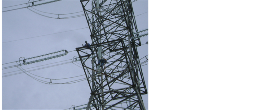
Figure 4. Connection of conducting cables to the measurement cable of the earth meter and preparation of conductors to measurements extraction.
The function of a resistance element is to limit the resistive layer for a protection quadrilateral area. Some resistance elements measure the resistance of the added RF line. The fault resistance values were obtained according to Equation (1), as given by [3] :
(1)
where:
・ in the voltage between phase and ground ( represents phase voltage A, B or C);
・ is the relay adjustment, which is equal to the line angle for the positive sequence impedance ;
・ is the phase current;
・ is the compensation factor of zero sequence.
The replicas of line impedances are set according to the reach of faults and adjusted to stop on 10˚ of positive phase sequence. The conditions in the array of protective relay signals are presented below, being:
・ , , the signals of the protection relay for Phase-Ground;
・ is the replica of the impedance to the stage;
・ is short-circuit voltage (effective value);
・ is the phase current of short-circuit (effective value);
・ is the position of the fault current;
・ is the neutral current of short-circuit (effective value);
・ is the phase angle short-circuit voltage;
・ is the phase angle of the short-circuit current;
・ is the phase angle of the neutral current of short circuit;
・ e are the parameters set in the relay for residual compensation.
The effect of fault on load (phase A) is calculated according to Equation (2):
(2)
The effect of fault on load to the (stage B and C) is calculated according to Equation (3):
(3)
For performance of distance protection simultaneous measurements of impedanceare performed with 6 loops (L1-E, L2-E, L3-E, L1-L2, L2-L3, L3-L1). Ground loops are evaluated when there is a recognition of fault to earth. Phase-phase loops are evaluated when the current and both phases exceeds this same set value, according to Equation (4).
(4)
where e are complex values measured and is the impedance of the line.
The impedance of the line is calculated according to Equation (5):
(5)
Generalizing the impedance calculation between phases (A and B) we obtain the Equation (6):
(6)
According to [3] the faulty stage is not always in phase with the total current of fault, IF, thus, is not very suitable as reference signal or polarization. The negative sequence current is a more efficient option. Equation (7) displays the measured residual current in each of the busbar presented in Table 1. For systems where (homogeneous systems), the phase angle of IR is equal to that of IF, regardless of the charging condition and fault resistance.
(7)
According to [3] , the major advantage of this fault resistance element is that its measurement is not significantly affected by the loading conditions. This allows the resistive limit to be set to a value greater than the apparent minimum charge impedance.
Relay SEL-421 uses MHO properties in the distant protection of phase and ground. Zones 1 (Z1P) and 2 (Z2P) are fixed in the “forward” direction, remaining zone 4 (Z4P) is adjusted forward, and zone 3 (Z3P) is adjusted as reverse, which results into three forward zones and one reverse zone, with high-speed distance elements. Those high-speed elements use voltage and current phasors derived from a medium cycle fast filter to provide opening times of sub-cycle order. The adjustments are automatically associated to the extent of the elements zone. Figure 5 shows the adjustments performed by the graphic editor of the AcSELerator QuickSet® software.
The range of MHO distance element of phase Z1P was set as 80% of the impedance of the positive sequence of the secure line. The distance element of phase Z2P is part of the implemented protection assisted by communication― POTT2 (Permissive Overreaching Transfer Trip), with directionality in the forward direction. The adopted range was of 200% of the impedance of positive sequence of the secure line. For the distance element of phase Z3P, with POTT2 scheme, the directionality was set in the reverse direction, allowing it to have a higher range when compared to Z2P. Thus, a range of 200% of the impedance of positive sequence of the secure line was adopted, and phase Z4P was adjusted as

Table 1. Values of Short-Circuit Current and Impedance Adopted in computer simulations of Power System HPS Santo Antônio.

Figure 5. Range of adjusted MHO distance elements.
conventional zone 2 protection (Z2P), that is, 120% of the impedance of positive sequence of the secure line. Figure 6 presents the adjustments for the logic diagram of distance protection.
2.4. Practical Scheme
The first step of the practical scheme is to simulate diverse fault conditions considering the resistance values of grounding (RT) measured in field and fault resistances (RF) collected calculated with PSCAD/EMTDC software. Those measurements are presented in Table 2.
The extraction of fault files is done in the second step in COMTRADE format (Common Format for Transient Data Exchange for power systems). In the third step, these files are provided to the simulator (Doble F6150) for the files in COMTRADE format for characterization of certain situations tests on the protection logic. The fourth step is characterized by the evaluation of the relay operation behavior regarding the simulated situations. Figure 7 shows the testing layout set in the laboratory.
An automation logic was implemented for the automatic voltage setting at all phases if this voltage exceeds 500 kV. If it is the case of a permanent condition of high voltage on the 500 kV level, an opening command is sent to the circuit breaker. Figure 8 shows the logic diagram of the automation setting on the phase voltage. A complete scheme of the TL was modeled by using the software PSCAD/EMTDC to simulate diverse fault conditions, as demonstrated in Figure 9.

Figure 6. Logic diagram of the elements of quadrilateral distance.

Figure 7. Complete test scheme of fault conditions.
Table 2. Input values for the software simulation.

Figure 8. Logic diagram for the automation in the phase voltage setting.
The circuit breakers B1 e B2 are monitored by function 50BF (Break Failure) and acted independently, as presented in Figure 10, for the logic diagram implemented in relay SEL-421, and as presented in Figure 11, for the modeled logic diagram in the software PSCAD/EMTDC [9] [10] .
Functions BFPU1 and BFPU2 in the SEL-421 relay are implemented and tested in a time based manner, in which it must be continually present to result in the trip for multiple faults of the fault protection logic of circuit breakers 1 and 2, with maximum operating time of ten cycles for B1 and B2. The detection logic of the high-speed open pole was set for a pickup current below the minimum charge current, providing sensitivity without harming the speed of the dropout time. This condition is met, even in scenarios where there is a delay that drops the current in the CT secondary to zero, due to the magnetic flow, the detection the of the circuit breaker opening is performed at high speed [11] [12] and [13] .


Figure 10. Logic diagram of the function and protection 50BF on SEL-421 for circuit breakers 1 and 2.

Figure 11. Logic diagram of functioning and protection of the distance and control of circuit breaker PSCAD/EMTDC.
3. Results
Figure 12 to Figure 21 present the graphical results of the fault situations applied on the SEL-421 relay, with the use of COMTRADE files that were loaded from the simulator Doble 6150. Those graphics also show the binaries performed in each fault situation.
For each test, Table 3 summarizes the measured ground RT (Ω), calculated fault resistances RF (Ω) and current IF (kA), the distance from which the relay identified the fault, the zones performed by the relay and the fault phase. Adopt as maximum value permissible in measurements of grounding system with the acquisition of 125 samples by 2.34 Ω value mesh, as constant calculation method in Annex B of the IEEE Standard 80-2015.
Table 3. Summary of the results obtained.

Figure 12. Test 1. Fault on phase B, RT = 2.40 Ω, RF = 19.10 Ω, Fault Distance, 131 meters, IF = 4.77 kA in Zone 1.

Figure 13. Test 2. Fault on phase B, RT = 2.21 Ω, RF = 20.60 Ω, Fault Distance, 100 meters, IF = 4.34 kA in Zone 1.
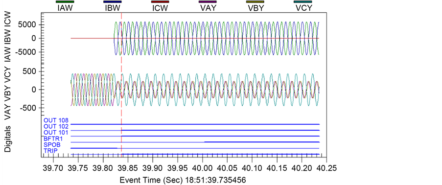
Figure 14. Test 3. Fault on phase B, RT = 2.26 Ω, RF = 21.00 Ω, Fault Distance, 123 meters, IF = 4.37 kA in Zone 1.

Figure 15. Test 4. Fault on phase B, RT = 2.73 Ω, RF = 18.30 Ω, Fault Distance, 1.00 kilometer, IF = 8.18 kA in Zone 1.

Figure 16. Test 5. Fault on phase C, RT = 1.74 Ω, RF = 16.40 Ω, Fault Distance, 174 meters, IF = 4.91 kA in Zone 2, Time of Trip 28.80 ms.

Figure 17. Test 6. Fault on phase C, RT = 1.73 Ω, RF = 19.62 Ω, Fault Distance, 300 meters, IF = 4.33 kA in Zone 1, Time of Trip 33.80 ms.

Figure 18. Test 7. Fault on phase C, RT = 1.58 Ω, RF = 18.30 Ω, Fault Distance, 100 meters, IF = 4.75 kA in Zone 1, Time of Trip 27.05 ms.

Figure 19. Test 8. Fault on phase A, RT = 1.82 Ω, RF = 18.20 Ω, Fault Distance, 100 meters, IF = 4.79 kA in Zone 1, Time of Trip 33.57 ms.

Figure 20. Test 9. Fault on phases A-B-C, RT = 2.80 Ω, RF = 20.41 Ω, Fault Distance, 1.39 kilometers, IF = 3.92 kA in Zone 1, Time of Trip 20.33 ms.

Figure 21. Test 10. Fault on phase B, RT = 2.40 Ω, RF = 19.10 Ω, Fault Distance, 131 meters, IF = 4.77 kA in Zone 1, Time of Trip 34.83 ms.
4. Conclusion
Based on the response results of the SEL-421 relay, it was possible to verify its correct usage for each applied fault condition, allowing the validation of the entire process. Results indicate the effectiveness of the resistance measuring method of global grounding (involving substation, engine room with lightning rod cables of the transmission line), and the simulation in the PSCAD/EMTDC of the interconnection system of Santo Antonio HPS to SIN. Finally, the suitability of the relay parametrization and the values obtained by the simulations were also verified, which were used to acquire the COMTRADE file that can be used as validation guidelines in protection studies. The high-current injection system is a reliable alternative for the potential drop method with low currents, as well as for determining the resistance or impedance of grounding systems.
Acknowledgements
The authors would like to acknowledge the financial support granted by CAPES.
Cite this paper
Araújo, C.M.B. and Trondoli, L.H.P.C. (2017) Testing through Fall of Potential with High Current Injec- tion in Grounding System in Transmission Line of 500 kV of Santo Antonio HPS. Open Access Library Journal, 4: e3323. http://dx.doi.org/10.4236/oalib.1103323
References
- 1. Edital de Leilao n.°007 (2008) Licitacao para a contratacao de servico publico de transmissao de energia elétrica”, Agencia Nacional de Energia Elétrica (ANEEL).
- 2. (2015) IEEE Guide for Safety in AC Substation Grounding. IEEE Std 80-2013 (Revision of IEEE Std 80-2000/Incorporates IEEE Std 80-2013/Cor 1-2015), 1-226.
- 3. Ferrer, H.J.A. and Schweitzer, E.O. (2010) Modern Solutions for Protection, Control, and Monitoring of Electric Power Systems. Schweitzer Engineering Laboratories.
- 4. MEGABRAS Ltd. Datasheet, High Frequency Earth Ground Tester-TM25R.
http://www.megabras.com/en/products/earth-tester/high-frequency-earth-tester-TM25R.php - 5. (2012) IEEE Guide for Measuring Earth Resistivity, Ground Impedance, and Earth Surface Potentials of a Grounding System. IEEE Std 81-2012 (Revision of IEEE Std 81-1983), 1-86.
- 6. Ma, Y. and Karady, G.G. (2009) Investigating Grounding Grid Integrity Based on the Current Injection Method. North American Power Symposium (NAPS), 1-5.
https://doi.org/10.1109/naps.2009.5484048 - 7. Sardi, J. and Chian, J.O.C. (2010) Evaluation of Surge Arrester Requirement for Overhead Transmission Line Using Electromagnetic Transient Program. IEEE International Conference on Power and Energy (PECon), 29 November-1 December 2010, 985-988.
https://doi.org/10.1109/pecon.2010.5697722 - 8. Huang, H., et al. (2013) Analysis of a Large Grounding System and Subsequent Field Test Validation Using the Fall of Potential Method. Energy and Power Engineering, 5, 1266.
https://doi.org/10.4236/epe.2013.54B240 - 9. Sardi, J. and Kadir, M.Z.A.A. (2013) Investigation on the Effects of Line Parameters to the Lightning Performance of 132 kV Kuala Krai-Gua Musang Transmission Line. IEEE 7th International Power Engineering and Optimization Conference (PEOCO), 3-4 June 2013, 594-599.
https://doi.org/10.1109/peoco.2013.6564617 - 10. Qais, M. and Khaled, U. (2015) Evaluation of Lightning Performance on Transmission System Sag. 50th International Universities Power Engineering Conference (UPEC), 1-4 September 2015, 1-6.
https://doi.org/10.1109/UPEC.2015.7339860 - 11. Goulkhah, M. and Gole, A.M. (2015) Practical Application of Waveform Relaxation Method for Testing Remote Protective Relays. IEEE International Conference on Industrial Technology (ICIT), 17-19 March 2015, 1381-1386.
https://doi.org/10.1109/icit.2015.7125290 - 12. Rohadi, N. and Zivanovic, R. (2012) Sensitivity Anal-ysis of a Fault Impedance Measurement Algorithm Applied in Protection of Parallel Transmission Lines. 9th IET International Conference on Advances in Power System Control, Operation and Management (APSCOM), 18-21 November 2012, 1-6.
https://doi.org/10.1049/cp.2012.2163 - 13. Ma, J., Yan, X., Fan, B., Liu, C. and Thorp, J.S. (2016) A Novel Line Protection Scheme for a Single Phase-to-Ground Fault Based on Voltage Phase Comparison. IEEE Transactions on Power Delivery, 31, 2018-2027.
https://doi.org/10.1109/TPWRD.2015.2507600