Int. J. Communications, Network and System Sciences, 2011, 4, 601-608
doi:10.4236/ijcns.2011.49072 Published Online September 2011 (http://www.SciRP.org/journal/ijcns)
Copyright © 2011 SciRes. IJCNS
Hemispherical DRA Antennas Mounted on or Embedded
in Circular Cylindrical Surface for Producing
Omnidirectional Radiation Pattern
Saber H. Zainud-Deen1, Noha A. El-Shalaby2, Kamal H. Awadalla1
1Faculty of Electronic Engineering, Menoufia University, Shibin el Kom, Egypt
2Faculty of Engineering, Kafrelsheikh University, Kafr el-Sheikh, Egypt
E-mail: anssaber@yahoo.com, Noha1511ahm@yahoo.com
Received June 29, 2011; revised August 4, 2011; accepted August 20, 2011
Abstract
The radiation characteristics of hemispherical DRA elements mounted on or embedded in a hollow circular
cylindrical ground structure are investigated. The performance of the DRA array which operates at about 1.8
Ghz, is studied. Factors influencing the array performance, such as the number of elements and element
spacing are explained. The perforated dielectric technique is used to design the array from a single dielectric
sheet. The overall profile of the antenna can be significantly reduced. The radiation patterns with respect to
the number of DRA elements are depicted.
Keywords: DRAs, FEM, FIT
1. Introduction
Cylindrical conducting surfaces with antennas fixed on
top are widespread in different systems such as aero-
space vehicles and satellites In these applications, the
antenna radiation pattern is needed to be almost omnidi-
rectional, and the antenna efficiency has to be high [1-4].
The dielectric resonator antenna (DRA) can offer all the
requirements for such applications [5-11]. DRA antenna
has great flexibility in shape, material and feeding
mechanisms. In addition, DRA resonant antennas can
have wide bandwidth and large angle of coverage. The
radiation characteristics of cylindrical and hemispherical
DRAs placed on or embedded in circular cylindrical and
spherical ground planes are investigated in [12-15].
In this paper, the performance of the hemispherical
DRA array elements mounted on or embedded in circular
cylindrical ground plane for producing omnidirectional
radiation pattern, which operates at about 1.8 GHz, is
studied. The array performance is very much influenced
by several factors, such as the number of elements and
elements spacing. These effects have been investigated
in this work. The perforated dielectric technique is used
to design the array from a single dielectric sheet. The
overall profile of the antenna can be significantly re-
duced. The perforation is implemented as a uniform lat-
tice of holes drilled through dielectric links that help in
fixing the antenna elements [16]. It can be seen that an
increase in the number of hemispherical DRA antennas
directly result in a better approximation of an omnidirec-
tional pattern. The hemispherical DRA antenna elements
are uniformly distributed along the circumference of a
finite hollow conducting cylinder. The radiation patterns
with respect to the number of DRA elements are investi-
gated based on the radiation characteristic. It will be seen
that an array of eight hemispherical DRAs is a good can-
didate for omnidirectional pattern. Numerical results are
obtained using the finite element method (FEM) and
compared with that calculated by the finite integration
technique (FIT) for authentication.
2. Methods of Solution
2.1. Finite Element Method
In this paper, the finite element method (FEM) is used to
determine the radiation characteristics of the antennas.
The finite element method is quite suitable for the analy-
sis of DRA antennas. The basic idea of the finite element
method is to divide the electromagnetic structure in a
number of elements which usually have the same shape
but can differ in size, as the elements shape could be
602 S. H. ZAINUD-DEEN ET AL.
rectangles or triangles for surfaces or cuboids and pyra-
mids for solid objects. The field within each element is
expanded in terms of a set of basis functions. These
functions are usually weighted and controlled by the
field values at the nodes of the element. A matrix equa-
tion is then formed, with the field values at the element
nodes as the unknowns. Solving this matrix equation the
unknowns can be determined [17-24].
2.2. Finite Integration Technique
The finite integration technique (FIT) is conceptually
different from the FET method. This is why it is used to
confirm the accuracy of the results. This method is very
versatile and suitable for quite a wide range of electro-
magnetic problems. The basic idea of this approach is to
discretize the application domain in a set of staggered
grids and apply Maxwell’s equations in the integral form
to such grids, so it is called Maxwell-Grid-Equations
(MGE). As usual in some of the numerical techniques,
the application will end up in matrix equations. The re-
sulting matrix equations of the discretized fields can be
used for determining the distribution of the fields in the
problem domain. The finite integration technique is rela-
tively faster than other numerical techniques such as the
finite difference time domain technique and the FEM
mentioned above. It has also relatively high flexibility in
modeling different geometric shapes and in handling
boundaries. It has to be noted that, from our experience
the results determined using the FEM are more accurate
than those obtained using the FIT due to the fact that the
FIT has to stick to a rectangular or cubical staggered
grids which are not adequate in fitting the curved
boundaries. More details about FIT can be found in
[25-30].
3. Numerical Results
An Array of Hemispherical DRAs Mounted on or
Embedded in Circular Cylindrical Surface
Figure 1 shows the array geometry of hemispherical
DRA elements which are equally spaced and placed on a
circular cylindrical ground plane. The hemispherical
DRA with dielectric constant εr = 8.9 is used. It has ra-
dius “a”, of 2.54 cm. A coaxial probe with radius of
0.075 cm excites each element. All the ports of the ele-
ments were fed with signals which are in phase and equal
in amplitude. The probe is located off the center by df =
1.74 cm with a height “h”, of 1.52 cm. The hemispheri-
cal DRA is designed to operate at 1.8 GHz. l the length
of the circular cylindrical ground plane, “lg”, is 50 cm.
The thickness of the cylindrical conductor is 0.6 mm, and
Figure 1. The geometry of hemispherical DRA array moun-
ted on a cylindrical ground.
the radius of the circular cylinder is “rg”. The simulated
reflection coefficient as a function of frequency and the
radiation pattern for one element, and two elements
mounted on circular cylindrical ground plane are illus-
trated in Figure 2. The radius of the circular cylindrical
ground is rg = 7.5 cm. The simulated results are calcu-
lated by using the FEM and compared with that calcu-
lated by FIT method. Good agreement is obtained.
As the resonance frequency is 1.8 GHz, i.e. λ = 16.67
cm, which is of the same order of the diameter of the
cylindrical ground plane, thus the back radiation is rela-
tively high. This high backward radiation has revealed
itself strongly in the radiation pattern of the single ele-
ment and also in that of the two oppositely mounted
elements. The results indicate clearly that the backward
radiation is not in phase with the forward radiation of the
other element which causes lower forward and backward
radiation, i.e. 0˚ and 180˚ directions, than the in-phase
radiation at 90˚ and 270˚ directions. In the same time, the
antenna bandwidth for the two element array has gone
down due to the effect of the other elements as seen from
the behavior of the reflection coefficient.
The radiation patterns with respect to the number of
DRA elements array are investigated by using FIT and
compared with FEM. Good agreement is obtained. It can
be seen that increasing the number of DRA elements in
the array result in a better approximation for an omnidi-
rectional pattern. When the numbers of DRA elements
are increased to five elements the ripple in the radiation
pattern is 7 dB. For six hemispherical DRA elements, the
ripple in the radiation pattern is reduced to be 2 dB as
shown in Figure 3. However, increasing the number of
elements brings them closer to each other which result in
strong coupling between them. This strong coupling re-
duces the reflection coefficient bandwidth and causes
Copyright © 2011 SciRes. IJCNS
S. H. ZAINUD-DEEN ET AL.
603
(a)
(b)
Figure 2. The reflection coefficient and radiation pattern at
rg = 7.5 cm. (a) The reflection coefficient; (b) The radiation
patterns.
(a)
(b)
(c)
(d)
Figure. 3. The radiation patterns of an array with different
elements at rg = 7.5 cm on cylindrical ground plane. (a) 3
elements; (b) 4 elements; (c) 5 elements; (d) Six elements.
Copyright © 2011 SciRes. IJCNS
604 S. H. ZAINUD-DEEN ET AL.
some difficulty in adjusting the feed for the antenna ele-
ments. (It has to be noted that no more than 9 DRA ele-
ments can be fixed on the ground plane circumference
according to the selected dimensions).
Figure 4 shows the reflection coefficient as a function
of frequency for one element, and also for two elements
when rg = 15 cm. Increasing the size of the cylindrical
ground plane has reduced the level of the diffracted field
which forms the back radiation for the single case as in
Figure 4(a). It indicates a lower effect of each element
on the other's radiation in the front direction. This is of
course due to the lower level of the diffracted field. In-
creasing the number of the elements as in Figures
5(a)-(c) the strong dips in the radiation pattern becomes
more diluted. As the number of the DRA elements
reaches 8 in this case, the ripple in the radiation pattern is
reduced to 3 dB as shown in Figure 5.
For more economy and for getting rid of the protrusion
of the DRA elements, a hemispherical DRA array with
elements embedded in cylindrical ground plane structure
loaded with protecting dielectric superstrate is proposed
as shown in Figure 6. The superstrate layer directly
loads the hemispherical DRA. It has a relative permittiv-
ity εrs = 2.2, a thickness hc = 27 cm and rc = 45 cm, as
shown in Figure 6. The reflection coefficient and the
radiation pattern for one element and three elements is
depicted in Figures 7(a) and (b). The results are pro-
duced for rg = 15 cm. The radiation patterns for 5 and 8
hemispherical DRA elements are illustrated in Figure 8.
The variation in the ripple in the radiation pattern by
increasing the number of embedded DRAs is nearly
producing similar variations as in the case of protruding
elements. But note that impedance bandwidth decreased
with embedded DRAs.
Another geometry of DRA array is shown in Figure 9.
The perforated dielectric technique is used to design the
array from a single dielectric sheet. The spacing and the
diameter of holes are used to determine the effective di-
electric constant of the material surrounding the DRA
elements, the effective dielectric constant, εreff, for the
perforated material can be calculated from [16].


2
2
π,1
234
h
reff r
h
R
S



Where Rh is the radius of the air holes, and Sh is the cen-
ter to center separation of the holes. This technique of
fabricating the DRA array is more practical, and feasible.
The reflection coefficients as a function of frequency for
one element and four elements are shown in Figure 10.
The radiation patterns in x-y plane for one, four and eight
elements around the circular cylindrical ground plane of
radius rg = 15 cm are shown in Figures 10 and 11. The
ripple in the radiation pattern is reduced by increasing
(a)
(b)
Figure 4. The reflection coefficient and radiation pattern at
rg = 15 cm. (a) The reflection coefficient; (b) The radiation
pattern.
Copyright © 2011 SciRes. IJCNS
S. H. ZAINUD-DEEN ET AL.
605
(a)
(b)
(c)
Figure 5. The radiation patterns of an array with different
elements on cylindrical ground plane, at rg = 15 cm. (a)
Three elements; (b) Five elements; (c) 8 elements.
Figure 6. The geometry of hemisphere DRAs array embed-
ded in a cylindrical ground.
(a)
(b)
Figure 7. The reflection coefficient and radiation pattern at
rg = 15 cm. (a) The reflection coefficient; (b) The radiation
pattern.
Copyright © 2011 SciRes. IJCNS
606 S. H. ZAINUD-DEEN ET AL.
(a)
(b)
Figure 8. The radiation patterns of an array with different
elements embedded in c ylindrical ground plane, rg = 15 cm.
(a) Five elements; (b) Eight elements.
Figure 9. The geometry of hemispherical DRA elements
with perforate d link on a circular cylindric al ground plane,
rg = 15 cm, Rh = 4.23 mm, Sh = 16.92 mm, th = 2.032 mm.
the number of DRA elements.
4. Conclusions
The performance of a hemispherical DRA antenna mounted
(a)
(b)
Figure 10. The reflection coefficient and radiation pattern
at rg = 15 cm. (a) The reflection coefficient; (b) The radia-
tion pattern.
Copyright © 2011 SciRes. IJCNS
S. H. ZAINUD-DEEN ET AL.
607
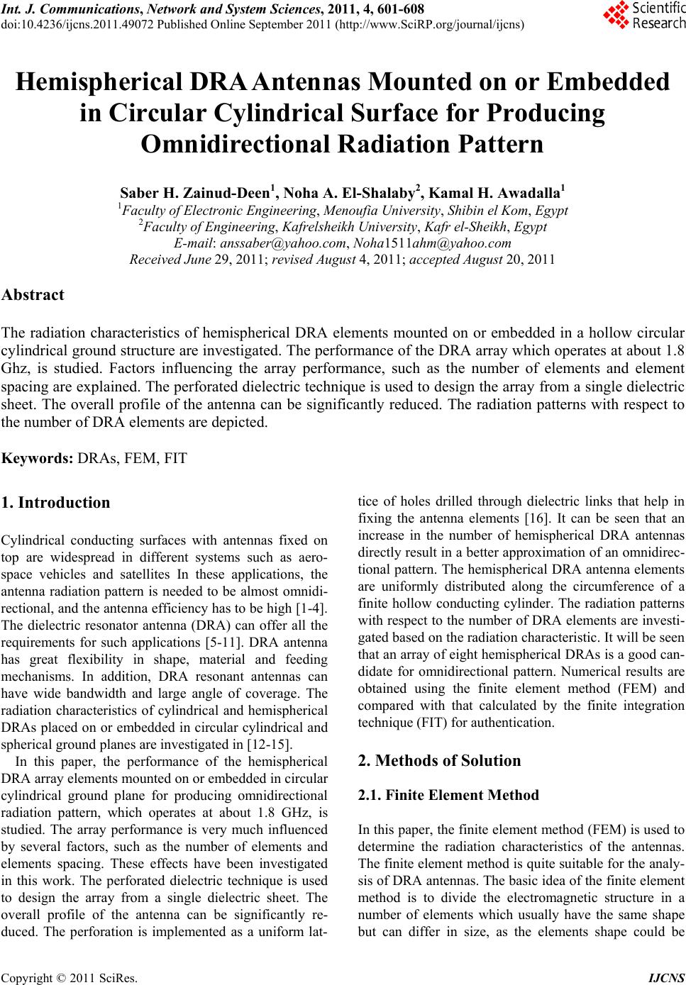
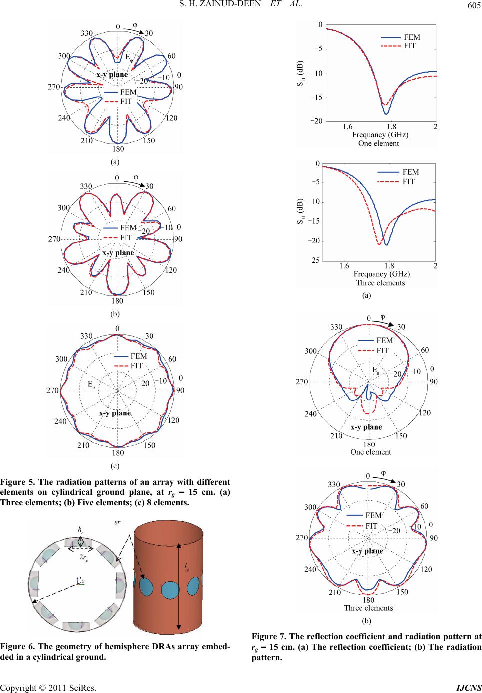
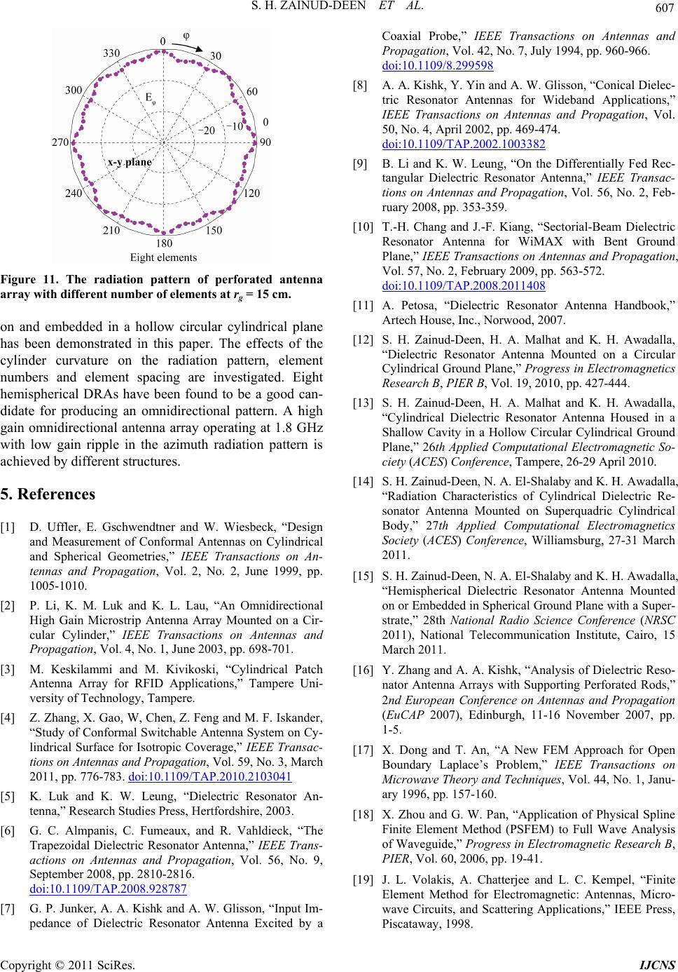
Figure 11. The radiation pattern of perforated antenna
array with different number of elements at rg = 15 cm.
on and embedded in a hollow circular cylindrical plane
has been demonstrated in this paper. The effects of the
cylinder curvature on the radiation pattern, element
numbers and element spacing are investigated. Eight
hemispherical DRAs have been found to be a good can-
didate for producing an omnidirectional pattern. A high
gain omnidirectional antenna array operating at 1.8 GHz
with low gain ripple in the azimuth radiation pattern is
achieved by different structures.
5. References
[1] D. Uffler, E. Gschwendtner and W. Wiesbeck, “Design
and Measurement of Conformal Antennas on Cylindrical
and Spherical Geometries,” IEEE Transactions on An-
tennas and Propagation, Vol. 2, No. 2, June 1999, pp.
1005-1010.
[2] P. Li, K. M. Luk and K. L. Lau, “An Omnidirectional
High Gain Microstrip Antenna Array Mounted on a Cir-
cular Cylinder,” IEEE Transactions on Antennas and
Propagation, Vol. 4, No. 1, June 2003, pp. 698-701.
[3] M. Keskilammi and M. Kivikoski, “Cylindrical Patch
Antenna Array for RFID Applications,” Tampere Uni-
versity of Technology, Tampere.
[4] Z. Zhang, X. Gao, W, Chen, Z. Feng and M. F. Iskander,
“Study of Conformal Switchable Antenna System on Cy-
lindrical Surface for Isotropic Coverage,” IEEE Transac-
tions on Antennas and Propagation, Vol. 59, No. 3, March
2011, pp. 776-783. doi:10.1109/TAP.2010.2103041
[5] K. Luk and K. W. Leung, “Dielectric Resonator An-
tenna,” Research Studies Press, Hertfordshire, 2003.
[6] G. C. Almpanis, C. Fumeaux, and R. Vahldieck, “The
Trapezoidal Dielectric Resonator Antenna,” IEEE Trans-
actions on Antennas and Propagation, Vol. 56, No. 9,
September 2008, pp. 2810-2816.
doi:10.1109/TAP.2008.928787
[7] G. P. Junker, A. A. Kishk and A. W. Glisson, “Input Im-
pedance of Dielectric Resonator Antenna Excited by a
Coaxial Probe,” IEEE Transactions on Antennas and
Propagation, Vol. 42, No. 7, July 1994, pp. 960-966.
doi:10.1109/8.299598
[8] A. A. Kishk, Y. Yin and A. W. Glisson, “Conical Dielec-
tric Resonator Antennas for Wideband Applications,”
IEEE Transactions on Antennas and Propagation, Vol.
50, No. 4, April 2002, pp. 469-474.
doi:10.1109/TAP.2002.1003382
[9] B. Li and K. W. Leung, “On the Differentially Fed Rec-
tangular Dielectric Resonator Antenna,” IEEE Transac-
tions on Antennas and Propagation, Vol. 56, No. 2, Feb-
ruary 2008, pp. 353-359.
[10] T.-H. Chang and J.-F. Kiang, “Sectorial-Beam Dielectric
Resonator Antenna for WiMAX with Bent Ground
Plane,” IEEE Transactions on Antennas and Propagation,
Vol. 57, No. 2, February 2009, pp. 563-572.
doi:10.1109/TAP.2008.2011408
[11] A. Petosa, “Dielectric Resonator Antenna Handbook,”
Artech House, Inc., Norwood, 2007.
[12] S. H. Zainud-Deen, H. A. Malhat and K. H. Awadalla,
“Dielectric Resonator Antenna Mounted on a Circular
Cylindrical Ground Plane,” Progress in Electromagnetics
Research B, PIER B, Vol. 19, 2010, pp. 427-444.
[13] S. H. Zainud-Deen, H. A. Malhat and K. H. Awadalla,
“Cylindrical Dielectric Resonator Antenna Housed in a
Shallow Cavity in a Hollow Circular Cylindrical Ground
Plane,” 26th Applied Computational Electromagnetic So-
ciety (ACES) Conference, Tampere, 26-29 April 2010.
[14] S. H. Zainud-Deen, N. A. El-Shalaby and K. H. Awadalla,
“Radiation Characteristics of Cylindrical Dielectric Re-
sonator Antenna Mounted on Superquadric Cylindrical
Body,” 27th Applied Computational Electromagnetics
Society (ACES) Conference, Williamsburg, 27-31 March
2011.
[15] S. H. Zainud-Deen, N. A. El-Shalaby and K. H. Awadalla,
“Hemispherical Dielectric Resonator Antenna Mounted
on or Embedded in Spherical Ground Plane with a Super-
strate,” 28th National Radio Science Conference (NRSC
2011), National Telecommunication Institute, Cairo, 15
March 2011.
[16] Y. Zhang and A. A. Kishk, “Analysis of Dielectric Reso-
nator Antenna Arrays with Supporting Perforated Rods,”
2nd European Conference on Antennas and Propagation
(EuCAP 2007), Edinburgh, 11-16 November 2007, pp.
1-5.
[17] X. Dong and T. An, “A New FEM Approach for Open
Boundary Laplace’s Problem,” IEEE Transactions on
Microwave Theory and Techniques, Vol. 44, No. 1, Janu-
ary 1996, pp. 157-160.
[18] X. Zhou and G. W. Pan, “Application of Physical Spline
Finite Element Method (PSFEM) to Full Wave Analysis
of Waveguide,” Progress in Electromagnetic Research B,
PIER, Vol. 60, 2006, pp. 19-41.
[19] J. L. Volakis, A. Chatterjee and L. C. Kempel, “Finite
Element Method for Electromagnetic: Antennas, Micro-
wave Circuits, and Scattering Applications,” IEEE Press,
Piscataway, 1998.
Copyright © 2011 SciRes. IJCNS
S. H. ZAINUD-DEEN ET AL.
Copyright © 2011 SciRes. IJCNS
608
[20] C. Mattiussi, “A Reference Discretization Strategy for the
Numerical Solution of Physical Field Problems,” Ad-
vances in Imaging and Electron Physics, Vol. 121, 2002,
pp. 144-211. doi:10.1016/S1076-5670(02)80027-1
[21] A. C. Polycarpou, “Introduction to Finite Element
Method in Electromagnetics,” Morgan & Claypool Pub-
lishers’ Series, Waterloo, 2006.
[22] Z. Chen and M. Ney, “The Method of Weighted Residu-
als: A General Approach to Deriving Time and Fre-
quency Domain Numerical Methods,” IEEE Antennas
and Propagation Magazine, Vol. 51, No. 1, February
2009, pp. 51-70. doi:10.1109/MAP.2009.4939019
[23] D. Jiao, M. Lu, E. Michielssen and J. Jin, “A Fast
Time-Domain Finite Element-Boundary Integral Method
for Electromagnetic Analysis,” IEEE Antennas and
Propagation Magazine, Vol. 49, No. 10, October 2001,
pp. 1453-1461. doi:10.1109/8.954934
[24] A. Mitchell, D. M. Kokotoff and M. W. Austin, “Im-
provement to the PML Boundary Condition in the FEM
Using Mesh Compression,” IEEE Transactions on Mi-
crowave Theory and Techniques, Vol. 50, No. 5, May
2002, pp. 1297-1302. doi:10.1109/22.999142
[25] T. Weiland, “A Discretization Method for the Solution of
Maxwell’s Equations for Six-Component Fields,” Elec-
tronics and Communications, AEU, Vol. 31, No. 3, March
1977, pp. 116-120.
[26] I. Munteanu1 and T. Weiland, “RF & Microwave Simu-
lation with the Finite Integration Technique—From Com-
ponent to System Design,” Scientific Computing in Elec-
trical Engineering Mathematics in Industry, Part III, Vol.
11, 2007, pp. 247-260.
[27] G. Benderskaya, “Numerical Methods for Transient
Field-Circuit Coupled Simulations Based on the Finite
Integration Technique and a Mixed Circuit Formulation,”
Ph. D. Thesis, Technischen Universitat Darmstadt, Darm-
stadt, 2007.
[28] U. van Rienen, “Frequency Domain Analysis of Wave-
guides and Resonators with FIT on Non-Orthogonal Tri-
angular Grids,” Progress in Electromagnetics Research
(PIER), Vol. 32, 2001, pp. 357-381.
doi:10.2528/PIER00080114
[29] A. Monorchio, A. R. Bretones, R. G. Martin, G. Manara
and R. Mittra, “A Hybrid Time Domain Technique Com-
bining the Finite Element, Finite Difference and Integral
Equation Methods,” In Proceedings IEEE Antenna and
Propagation Society International Symposium, Salt Lake
City, Vol. 2, 2000, pp. 733-736.
[30] S. M. Rao, G. K. Gothard and D. R. Wilton, “Application
of Finite-Integral Technique to Electromagnetic Scatter-
ing by Two-Dimensional Cavity-Backed Aperture in a
Ground Plane,” IEEE Transactions on Antennas and
Propagation, Vol. 46, No. 5, May 1998, pp. 679-685.
doi:10.1109/8.668911