Paper Menu >>
Journal Menu >>
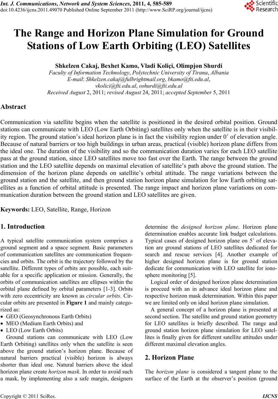 Int. J. Communications, Network and System Sciences, 2011, 4, 585-589 doi:10.4236/ijcns.2011.49070 Published Online September 2011 (http://www.SciRP.org/journal/ijcns) Copyright © 2011 SciRes. IJCNS The Range and Horizon Plane Simulation for Ground Stations of Low Earth Orbiting (LEO) Satellites Shkelzen Cakaj, Bexhet Kamo, Vladi Koliçi, Olimpjon Shurdi Faculty of Information Technology, Polytechnic University of Tirana, Albania E-mail: Shkelzen.cakaj@fulbrightmail.org, bkamo@fti.edu.al, vkolici@fti.edu.al, oshurdi@fti.edu.al Received August 2, 2011; revised August 24, 2011; accepted September 5, 2011 Abstract Communication via satellite begins when the satellite is positioned in the desired orbital position. Ground stations can communicate with LEO (Low Earth Orbiting) satellites only when the satellite is in their visibil- ity region. The ground station’s ideal horizon plane is in fact the visibility region under 0˚ of elevation angle. Because of natural barriers or too high buildings in urban areas, practical (visible) horizon plane differs from the ideal one. The duration of the visibility and so the communication duration varies for each LEO satellite pass at the ground station, since LEO satellites move too fast over the Earth. The range between the ground station and the LEO satellite depends on maximal elevation of satellite’s path above the ground station. The dimension of the horizon plane depends on satellite’s orbital attitude. The range variations between the ground station and the satellite, and then ground station horizon plane simulation for low Earth orbiting sat- ellites as a function of orbital attitude is presented. The range impact and horizon plane variations on com- munication duration between the ground station and LEO satellites are given. Keywords: LEO, Satellite, Range, Horizon 1. Introduction A typical satellite communication system comprises a ground segment and a space segment. Basic parameters of communication satellites are communication frequen- cies and orbits. The orbit is the trajectory follow ed by th e satellite. Different types of orbits are possible, each suit- able for a specific application or mission. Generally, the orbits of communication satellites are ellipses within the orbital plane defined by orbital parameters [1-3]. Orbits with zero eccentricity are known as circular orbits. Cir- cular orbits are presented in Figure 1 and mainly catego- rized as: GEO (Geosynchronous Earth Orbits) MEO (Medium Earth Orbits) and LEO (Low Earth Orbits) Ground stations can communicate with LEO (Low Earth Orbiting) satellites only when the satellite is seen above the ground station’s horizon plane. Because of natural barriers practical (visible) horizon is always shorter than ideal one. Natural barriers above the ideal horizon plane create horizon mask. In order to avoid such a mask, by implementing also a safe margin, designers determine the designed horizon plane. Horizon plane determination enables accurate link budget calculations. Typical cases of designed horizon plane on 5˚ of eleva- tion are ground stations of LEO satellites dedicated for search and rescue services [4]. Another example of higher designed horizon plane is for ground station dedicate for communication with LEO satellite for iono- sphere monitoring [5]. Logical order of designed horizon plane determination is proceed with an in advance ideal horizon plane and respective horizon mask determinatio n. Within this paper we are limited only on ideal horizon plane simulation. A general concept of a horizon plane is presented at second section. The satellite and ground statio n geometry for LEO satellites is briefly described. The range and ground station horizon plane simulation for LEO satel- lites is finally given for different satellite attitudes under different maximal elevation angles. 2. Horizon Plane The horizon plane is considered a tangent plane to the surface of the Earth at the observer’s position (ground 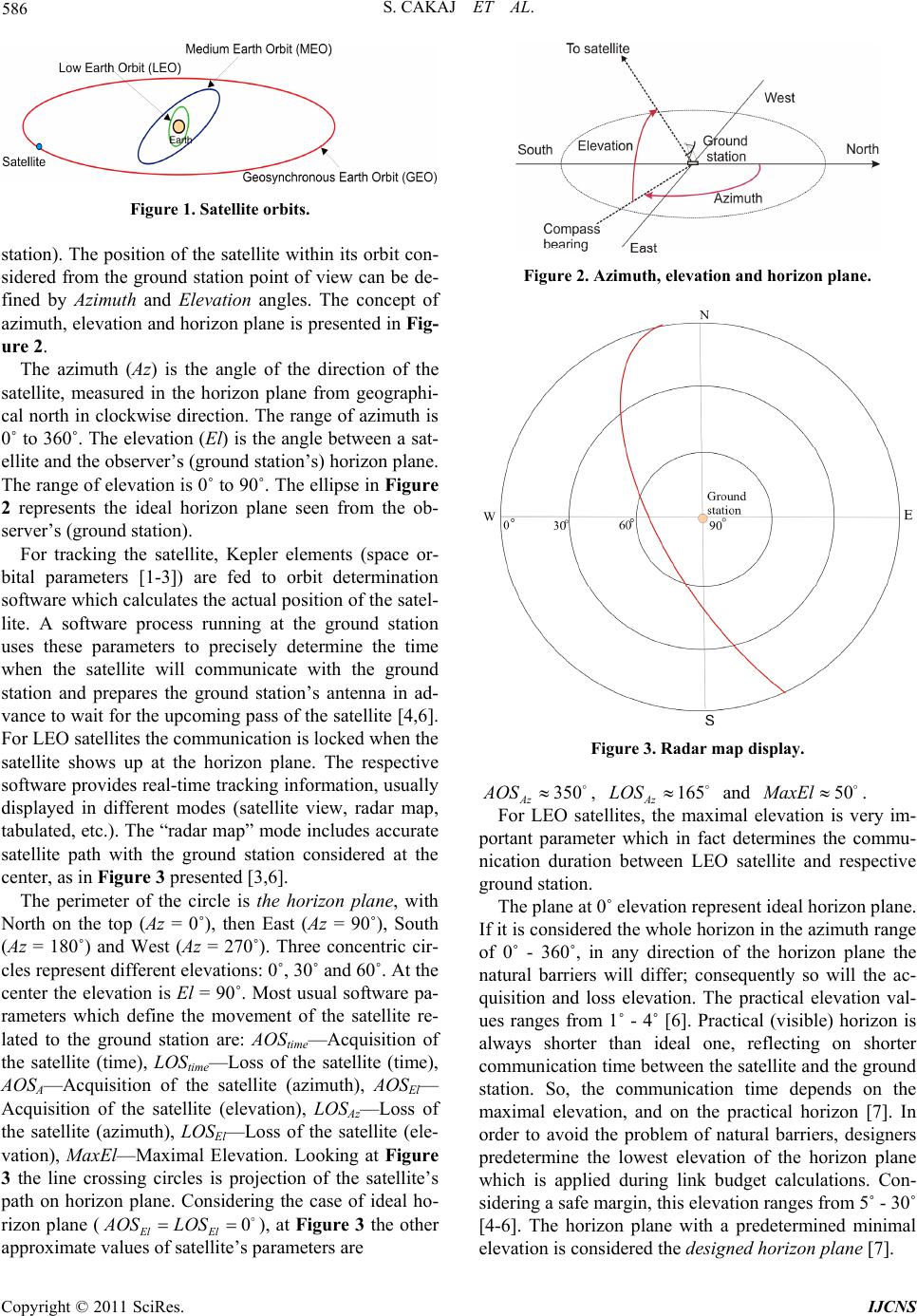 586 S. CAKAJ ET AL. Figure 1. Satellite orbits. station). The position of the satellite with in its orbit con- sidered from the ground station point of view can be de- fined by Azimuth and Elevation angles. The concept of azimuth, elevation and horizon plane is presented in Fig- ure 2. The azimuth (Az) is the angle of the direction of the satellite, measured in the horizon plane from geographi- cal north in clockwise direction. The range of azimuth is 0˚ to 360˚. The elevation (El) is the angle between a sat- ellite and the observ er’s (ground station ’s) horizon plane. The range of elevation is 0˚ to 90˚. The ellip se in Figure 2 represents the ideal horizon plane seen from the ob- server’s (ground station). For tracking the satellite, Kepler elements (space or- bital parameters [1-3]) are fed to orbit determination software which calculates the actual position of the satel- lite. A software process running at the ground station uses these parameters to precisely determine the time when the satellite will communicate with the ground station and prepares the ground station’s antenna in ad- vance to wait for the upcoming p ass of the satellite [4,6 ]. For LEO satellites the communicatio n is locked when th e satellite shows up at the horizon plane. The respective software provides real-time tracking information , usually displayed in different modes (satellite view, radar map, tabulated, etc.). The “radar map” mode includes accurate satellite path with the ground station considered at the center, as in Figure 3 presented [3,6]. The perimeter of the circle is the horizon plane, with North on the top (Az = 0˚), then East (Az = 90˚), South (Az = 180˚) and West (Az = 270˚). Three concentric cir- cles represent different elevations: 0˚, 30˚ and 60˚. At the center the elevation is El = 90˚. Most usual software pa- rameters which define the movement of the satellite re- lated to the ground station are: AOStime—Acquisition of the satellite (time), LOStime—Loss of the satellite (time), AOSA—Acquisition of the satellite (azimuth), AOSEl— Acquisition of the satellite (elevation), LOSAz—Loss of the satellite (azimuth), LOSEl—Loss of the satellite (ele- vation), Ma xEl—Maximal Elevation. Looking at Figure 3 the line crossing circles is projection of the satellite’s path on horizon plane. Considering the case of ideal ho- rizon plane (), at Figure 3 the other approximate values of satellite’s parameters are 0 El El AOS LOS Figure 2. Azimuth, elevation and hor izon plane. Figure 3. Radar map display. 350 Az AOS , and . 165 Az LOS50MaxEl For LEO satellites, the maximal elevation is very im- portant parameter which in fact determines the commu- nication duration between LEO satellite and respective ground station. The plane at 0˚ elevation represent ideal horizon plane. If it is cons idered the whol e horizo n in the az imuth range of 0˚ - 360˚, in any direction of the horizon plane the natural barriers will differ; consequently so will the ac- quisition and loss elevation. The practical elevation val- ues ranges from 1˚ - 4˚ [6]. Practical (visible) horizon is always shorter than ideal one, reflecting on shorter communication time between the satellite an d the ground station. So, the communication time depends on the maximal elevation, and on the practical horizon [7]. In order to avoid the problem of natural barriers, designers predetermine the lowest elevation of the horizon plane which is applied during link budget calculations. Con- sidering a safe margin, this elevation ranges from 5˚ - 30˚ [4-6]. The horizon plane with a predetermined minimal elevation is considered the desi gned horizon pla ne [7]. Copyright © 2011 SciRes. IJCNS  S. CAKAJ ET AL. 587 3. Slant Range for LEO Satellites The basic geometry between a LEO satellite and ground station is depicted in Figure 4. The two points indicate th e satellite (SAT) and ground station (P), and then the third is the Earth’s center. The subsatellite point is indicated by T (T is the point where the joining line of the satellite and Earth’s center inter- sect the Earth’s surface). Distance d represents slant range between a satellite and ground station. This range changes over time since the satellite flies too fast above the ground station . In Figure 4, the radius r is: E rR H (1) RE = 6378 km is Earth’s radius and H is LEO satellite’s attitude. The lin e crossing point P ind icates tangent plan e to Earth’s surface at point P, what by definition is in fact ideal horizon plane. The angle formed between ideal horizon plane and the slant range is elevation angle 0 . The triangle from Figure 4 brought in plane lo oks like in Figure 5 [8]. Two sides of this triangle are usually known (the dis- tance from the ground station to the Earth’s center RE = 6378 km, and distance form the satellite to Earth’s cen- ter-orbital radius). The angle under which the satellite sees the ground station is called nadir angle. There are four variables in this triangle: 0 —is elevation angle, 0 —is nadir angle, 0 —is central angle and d is slant range. As soon as two quantities are known, the others can be found with the following equations [8]: 000 90 (2) 0 cos sindr 0 (3) 0 sin sin e dR 0 (4) The most a ske d pa r am e ter is the s lant ra nge d (distance from the ground station to the satellite). This parameter will be used during the link budget calculation, and it is expressed through elev ation angle 0 . Applying cosines law for triangle at Figure 5 yields: 222 0 2cos 90 EE rRd Rd (5) Solving Equation (5) by d, yields: 2 20 cos sin EE r dR R0 (6) Substituting, E rHR at Equation (6) finally we will get the slant range as function of el evation angle 0 : 2 20 cos sin E EE HR dR R Figure 4. Ground station geometry. Figure 5. Ground station geometry. or elevation 0 expressed for known slant range d as: 2 0 2 sin 2 E E H HR d dR (8) For ) 2(2 E dHHR yields out 00 sin 00 , for dH yields out sin . 00 The range under the lowest elevation angle represents the worst link budget case, since that range represents the maximal possible distance between the ground station and the satellite. More power is required to overcome larger distance. Thus a trade off should be applied, in order to optimize the required transmit power and the designed horizon plane. 1 90 4. Horizon Plane Simulation for Ground Stations of LEO Satellites 0 (7) LEO satellites have very wide applications, from remote sensing of oceans, through analyses on Earth’s climate changes, Earth’s imagery with high resolution or astro- nomical purposes [9]. LEOs are just above Earth’s at- mosphere, where there is almost no air to cause drag on the satellite and reduce its speed. Less energy is required to launch a satellite into this type of orbit than into any other orbit [2,3]. LEO altitudes range from 275 km up to 1400 km limited by Van Allen radiation effects (sensors, integrated circuits and solar cells can be damage d by this radiation) [10]. Goal of this simulation is to conclude about slant range and horizon plane variations for a ground station Copyright © 2011 SciRes. IJCNS 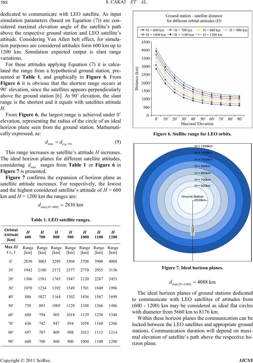 588 S. CAKAJ ET AL. dedicated to communicate with LEO satellite. As input simulation parameters (based on Equation (7)) are con- sidered maximal elevation angle of the satellite’s path above the respective ground station and LEO satellite’s attitude. Considering Van Allen belt effect, for simula- tion purposes are considered attitudes form 600 km up to 1200 km. Simulation expected output is slant range variations. For these attitudes applying Equation (7) it is calcu- lated the range from a hypothetical ground station, pre- sented at Table 1, and graphically in Figure 6. From Figure 6 it is obvious that the shortest range occurs at 90˚ elevation, since the satellites appears perpendicularly above the ground station [6]. At 90˚ elevation, the slant range is the shortest and it equals with satellites attitude H. From Figure 6, the largest range is achieved under 0˚ elevation, representing the radius of the circle of an ideal horizon plane seen from the ground station. Mathemati- cally expressed, as: 0 max( 0) dd (9) This range increases as satellite’s attitude H increases. The ideal horizon planes for different satellite attitudes, considering max ranges from Table 1 or Figure 6 in Figure 7 is presented. d Figure 7 confirms the expansion of horizon plane as satellite attitude increases. For respectively, the lowest and the highest cons idered satellite’s attitude o f H = 600 km and H = 1200 km the ranges are: max 6002830 km H d Table 1. LEO satellite ranges. Orbital Attitude [km] H 600 H 700 H 800 H 900 H 1000 H 1100 H 1200 Max El (0 ) Range [km] Range [km] Range [km] Range [km] Range [km] Range [km] Range [km] 0˚ 2830 3065 3289 3504 3708 39004088 10˚ 1942 2180 2372 2577 2770 29553136 20˚ 1386 1581 1765 1947 2120 22872453 30˚ 1070 1234 1392 1549 1701 18491996 40˚ 886 1027 1164 1302 1436 15671698 50˚ 758 883 1005 1128 1248 13661486 60˚ 680 794 905 1018 1129 12381348 70˚ 636 742 847 954 1058 11601266 80˚ 697 707 809 908 1012 11131214 90˚ 600 700 800 900 1000 11001200 Figure 6. Stellite range for LEO orbits. Figure 7. Ideal horizon planes. max 12004088 km H d The ideal horizon planes of ground stations dedicated to communicate with LEO satellites of attitudes from (600 - 1200) km may be considered as ideal flat circles with diam et er from 5660 km to 8176 km. Within these horizon planes the communication can be locked between the LEO satellites and appropriate gr ou nd stations. Communication duration will depend on maxi- mal elevation of satellite’s path above the respective ho- rizon plane. Copyright © 2011 SciRes. IJCNS  S. CAKAJ ET AL. Copyright © 2011 SciRes. IJCNS 589 Considering above analysis, the communication dura- tion between LEO satellites and the appropriate ground station usually takes (5 - 15) minutes, few times (6 - 8) during the day. This too short communication time makes necessity for horizon plane determination as a precondi- tion of optimized communication (data download) be- tween the LEO satellite and respective ground station. 5. Conclusions The communication duration between the LEO satellite and respective ground station depends on maximal ele- vation of satellite’s path over the ground station and largeness of the hor izon plane. For ground stations dedicated to communicate with LEO satellites the ideal horizon plane can be considered as a flat circle with diameter ranging approximately from 6000 km to 8000 km. Because of natural barriers or too high buildings in urban areas, practical horizon plane always differs (smaller) from the ideal one. Through simulation it is confirmed that the horizon plan expands as satellite’s attitude increases, conse- quently providing longer communication between satel- lite and appropriate grou nd station. Considering the ideal horizon plane and the respective mask because of natural barriers, ground station design- ers by applying a safe margin, successfully define the designed horizon plane for the planned satellite ground station to be installed. 6. References [1] D. Roddy, “Satellite Communications,” McGraw Hill, Ne w York, 2006. [2] M. Richharia, “Satellite Communication Systems,” McGraw Hill, New York 1999. [3] Sh. Cakaj, W. Keim and K. Malaric, “Communication Duration with Low Earth Orbiting Satellites,” Proceed- ings of IEEE, IASTED, 4th International Conference on Antennas, Radar and Wave Propagation, Montreal, 30 May-1 June 2007, pp. 85-88. [4] Sh. Cakaj, M. Fitzma urice, J. Reich and E. Foster, “Simu- lation of Local User Terminal Implementation for Low Earth Orbiting (LEO) Search and Rescue Satellites,” The 2nd International Conference on Advances in Satellite and Space Communications SPACOMM 2010, IARIA, Athens, 13-19 June 2010, pp. 140-145. [5] E. A. Essex, “Monitoring the Ionosphere/Plasmasphere with Low Earth Orbit Satellites: The Australian Microsa- tellite FedSat,” Cooperative Research Center for Satellite Systems, Department of Physics, La Trobe University, Bundoora, 2010. [6] Sh. Cakaj and K. Malaric, “Rigorous Analysis on Per- formance of LEO Satellite Ground Station in Urban En- vironment,” International Journal of Satellite Communi- cations and Networking, Vol. 25, No. 6, 2007, pp. 619- 643. [7] Sh. Cakaj, “Practical Horizon Plane and Communication Duration for Low Earth Orbiting (LEO) Satellite Ground Stations,” WSEAS Journal: Transactions on Communica- tions, Vol. 8, No. 4, April 2009, pp. 373-383. [8] G. D. Gordon and W. L. Morgan, “Principles of Commu- nication Satellites,” John Wiley & sons, Inc., Hoboken, 1993. [9] R. E. Zee and P. Stibrany, “The MOST Microsatellite: A Low-Cost Enabling Technology for Future Space Science and Technology Missions,” Canadian Aeronautics and Space Journal, Vol. 48, No. 1, 2002, pp. 1-10. [10] http://www.answers.com/topic/van-allen-radiation-belt, 2011. |