Paper Menu >>
Journal Menu >>
 Int. J. Communications, Network and System Sciences, 2011, 4, 568-577 doi:10.4236/ijcns.2011.49068 Published Online September 2011 (http://www.SciRP.org/journal/ijcns) Copyright © 2011 SciRes. IJCNS A Simple Symbol Estimation for Soft Information Relaying in Cooperative Relay Channels Azlan Abd Aziz, Yasunori Iwanami Department of C om put e r Sci ence and Engin eer i ng, Graduate School of Engineering, Nagoya Institute o f Technology, Nagoya, Japan E-mail: azlan@rose.elcom.nitech.ac.jp Received July 12, 2011; revised August 11, 2011; accepted August 22, 2011 Abstract This paper proposes Symbol-based Soft Forwarding (SSF) protocol for coded transmissions which is based on a simple proposed soft symbol estimation at relay nodes. We present a simple strategy of forwarding soft information based on a simple linear summation of likelihood functions of each symbol. Specifically, with SSF, we demonstrate that exclusion of decoding at the relays costs no significant performance loss. To vali- date our claims, we examine bit error rate (BER) performance for the proposed scheme against the baseline SF scheme through computer simulations. We find that the proposed scheme can obtain considerable per- formance gains compared to the conventional relaying protocol. Keywords: Symbol Estimation, Soft Information Relaying, Cooperative Relay, Symbol LLR 1. Introduction Soft Forwarding (SF) [1,2] has been widely studied as an effective relaying protocol which combines the features of Amplify-and-Forward (AF) and Decode-and-Forward (DF) [3]. AF preserves the reliability information but ignores the channel coding. DF, however, enjoys the coding gain but suffers from the error propagation. Therefore, SF is introduced to reap the benefits of both previous strategies with applications to various systems. For instance, SF can be represented by the bit log likeli- hood ratios (LLR) values generated by a channel decoder. Soft values are re-transmitted by relays in different ways e.g., based on the power constraint at relays (AF strategy) as in [1], or transmitting the expectation values in terms of the mean squared error (MSE) namely Estimate- and-Forward (ENF) [2,4], Decode-Estimate-Forward sch- eme (DENF) [5], or Soft-Decode-and-Forward (SDF) [6]. If these works assume Gaussian distribution in bit LLR computations for simplicity, [6,7] improve LLR compu- tations based on more accurate distribution. Moreover, these methods require high search operations in bit LLR computations, especially if higher modulations are ap- plied. In conventional SF schemes, channel between source- relay link has to be highly reliable enough to ensure er- ror-free re-transmission at the relay. In [1,2], to have reliable re-transmissions from the relays, the authors employ error correcting codes and cyclic redundancy checks (CRC) to assist the detection at the destination. Generally, early coded cooperative relay schemes used convolutional or Turbo codes [5-8], but recently apply- ing Low Density Parity Check (LDPC) codes have gained more attention [9]. A drawback for single-input single output (SISO) coded scheme under block fading channel is the lack of coding gain due to the constant fading coefficient in each block of codeword [10]. This becomes a challenging task for LDPC coded schemes to cope with the erroneous and unreliable decoded signals at the relays. Another strategy to solve error propagations from the relays has been proposed in [11,12] based on Maximum Likelihood (ML) criterion bit LLR combining at the destination. However, this strategy increases the computational complexity at the destination due to the requirement of perfect S-R channel knowledge for opti- mal detection. Unlike [1,2,5], which require bit-wise detection and decoding at relays, we propose a simple relaying strategy which is known as Symbol-based Soft Forwarding (SSF). This method provides a novel soft symbol estimation and a simple forwarding strategy by transmitting the expecta- tion values from a linear combination of posteriori prob- abilities of each symbol in the constellation set. In par- ticular, this strategy avoids severe impact of decoding 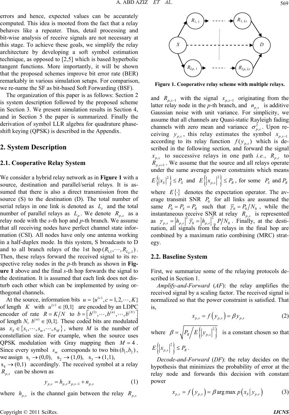 A. ABD AZIZ ET AL. 569 errors and hence, expected values can be accurately computed. This idea is mooted from the fact that a relay behaves like a repeater. Thus, detail processing and bit-wise analysis of receive signals are not necessary at this stage. To achieve these goals, we simplify the relay architecture by developing a soft symbol estimation technique, as opposed to [2,5] which is based hyperbolic tangent functions. More importantly, it will be shown that the proposed schemes improve bit error rate (BER) remarkably in various simulation setups. For comparison, we re-name the SF as bit-based Soft Forwarding (BSF). The organization of this paper is as follows: Section 2 is system description followed by the proposed scheme in Section 3. We present simulation results in Section 4, and in Section 5 the paper is summarized. Finally the derivation of symbol LLR algebra for quadrature phase- shift keying (QPSK) is described in the Appendix. 2. System Description 2.1. Cooperative Relay System We consider a hybrid relay network as in Figure 1 with a source, destination and parallel/serial relays. It is as- sumed that there is also a direct transmission from the source (S) to the destination (D). The total number of serial relays in one link is denoted as s L and the total number of parallel relays as p L. We denote , p s as a relay node with the s-th hop an d p-th bran ch. We assume that all receiving nodes have perfect channel state infor- mation (CSI). All nodes have only one antenna working in a half-duplex mode. In this system, S broadcasts to D and to all branch relays of the 1st hop1,1 ,1 p L. Then, these relays forward the received signal to its re- spective relay nodes in the p-th branch as shown in Fig- ure 1 above and th e final s-th hop forwards the sign al to the destination. It is assumed that each link does not dis- turb each other which can be implemented by using or- thogonal chan nels. R (,,R) } R At the source, information bits of length with are encoded by an LDP C encoder of rate () {,1,2,, c uuc K K() {0 ,1} c u RKN to of length N, (1)()( ,, ,, nN bb bb ) ()n{0,1} b ,, . These coded bits are modulated as 1SmM ,, x ss s, where M is the number of constellation size. For example, when the source uses QPSK modulation with Gray mapping then 4 M . Since every symbol m s corresponds to two bits, we assign 1 2 3 accordingly. The received symbol at a relay 12 (, )bb , s(1,1),s (0,0), s(1,0) 4 s (0,1) , p s R can be shown as ,,,1, p spsps p yhxn s (1) where , p s h is the channel gain between the relay , p s R S D R1, 1 R1, Ls RLp, 1 RLp, Ls Figure 1. Cooperative relay scheme with multiple relays. and ,1 p s R with the signal ,1 p s originating from the latter relay node in the p-th branch, and , x p s is additive Gaussian noise with unit variance. For simplicity, we assume that all channels are Quasi-static Rayleigh fading channels with zero mean and variance n 2, p s . Upon re- ceiving , p s, this relay estimates the symbol ,1 y p s x according to its relay function , () p s f y which is de- scribed in the following section, and forward the signal , p s x to successive relays in one path i.e., , p s to ,1 R p s R . We assume that the source and all relays operate under the same average power constraints which means 2 S Ex P S and 2 , p s Ex PR , for some and SR PP where E denotes the expectation operator. The av- erage transmit SNR 0 for all links are assumed the same 0SR P PPP such that 000 PN , while the instantaneous receive SNR at relay , p s is represented as R 22 hhPN ,, 0, 0 0 ps psps. Finally, at the desti- nation, all signals from the relays in the final hop are combined by a maximum ratio combining (MRC) strat- egy. 2.2. Baseline System First, we summarize some of the relaying protocols de- scribed in Section 1. Amplify-and-Forward (AF): the relay amplifies the received signal by a scaling factor. The received signal is normalized so that the power constraint is satisfied. That is, ,,, p spsps x fy y (2) where 2 ,Rps PEy is a constant chosen so that 2 , p sR Ex P . Decode-and-Forward (DF): the relay decides on the hypothesis that minimizes the probability of error at the relay node and forwards this decision with constant power ,, argmax , p sps Sps x fy pxy (3) Copyright © 2011 SciRes. IJCNS 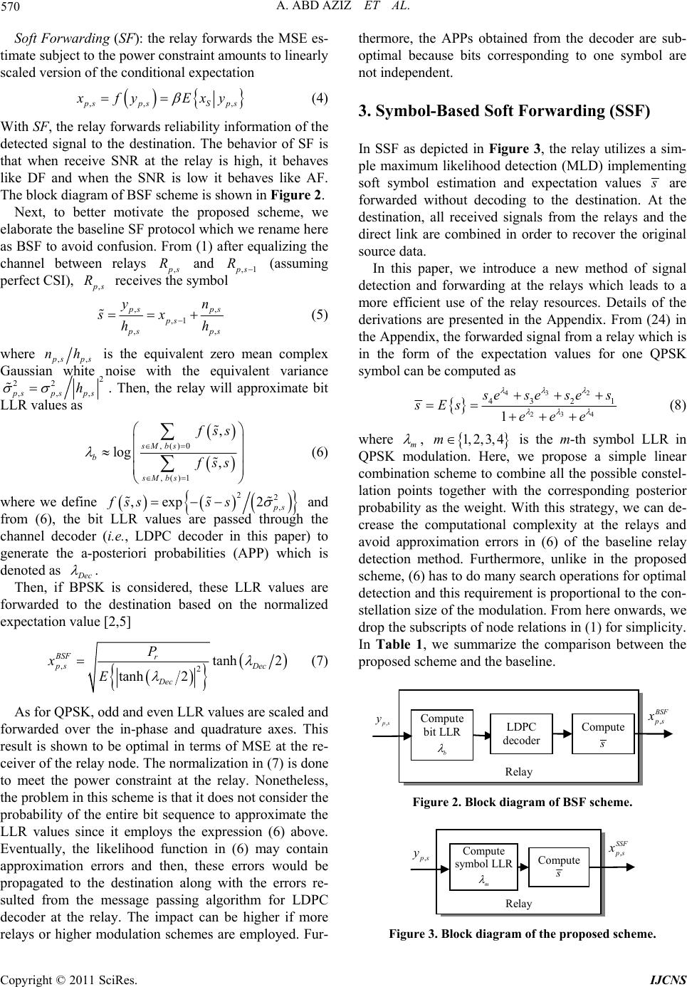 570 A. ABD AZIZ ET AL. Soft Forwarding (SF): the relay forwards the MSE es- timate subject to the power constraint amounts to linearly scaled version of the conditional expectation ,, , p sps Sp xfy Exy s (4) With SF, the relay forwar ds reliability information of the detected signal to the destination. The behavior of SF is that when receive SNR at the relay is high, it behaves like DF and when the SNR is low it behaves like AF. The block diagram of BSF scheme is shown in Figure 2. Next, to better motivate the proposed scheme, we elaborate the baseline SF protocol which we rename here as BSF to avoid confusion. From (1) after equalizing the channel between relays , p s and R,1 p s R (assuming perfect CSI), , p s R receives the symbol , ,1 ,, , p s ps ps p sp yn sx hh s (5) where ,, p sps nh is the equivalent zero mean complex Gaussian white noise with the equivalent variance 2 22 ,,,psps ps h . Then, the relay will approximate bit LLR values as , () 0 , ()1 , log , sMbs b sMbs f ss f ss (6) where we define 22, ,exp 2 ps fsss s and from (6), the bit LLR values are passed through the channel decoder (i.e., LDPC decoder in this paper) to generate the a-posteriori probabilities (APP) which is denoted as D ec . Then, if BPSK is considered, these LLR values are forwarded to the destination based on the normalized expectation value [2,5] ,2tanh 2 tanh 2 BSF r ps Dec Dec P xE (7) As for QPSK, odd and even LLR values are scaled and forwarded over the in-phase and quadrature axes. This result is shown to be optimal in terms of MSE at the re- ceiver of the relay node. The normalization in (7) is done to meet the power constraint at the relay. Nonetheless, the problem in this scheme is that it does not consider the probability of the entire bit sequence to approximate the LLR values since it employs the expression (6) above. Eventually, the likelihood function in (6) may contain approximation errors and then, these errors would be propagated to the destination along with the errors re- sulted from the message passing algorithm for LDPC decoder at the relay. The impact can be higher if more relays or higher modulation schemes are employed. Fur- thermore, the APPs obtained from the decoder are sub- optimal because bits corresponding to one symbol are not independent. 3. Symbol-Based Soft Forwarding (SSF) In SSF as depicted in Figure 3, the relay utilizes a sim- ple maximum likelihood detection (MLD) implementing soft symbol estimation and expectation values s are forwarded without decoding to the destination. At the destination, all received signals from the relays and the direct link are combined in order to recover the original source data. In this paper, we introduce a new method of signal detection and forwarding at the relays which leads to a more efficient use of the relay resources. Details of the derivations are presented in the Appendix. From (24) in the Appendix, the forwarded signal from a relay which is in the form of the expectation values for one QPSK symbol can be computed as 3 42 3 24 432 1 1 s eseses sEs eee (8) where m , 1, 2,3, 4m is the m-th symbol LLR in QPSK modulation. Here, we propose a simple linear combination scheme to combine all the possible constel- lation points together with the corresponding posterior probability as the weight. With this strategy, we can de- crease the computational complexity at the relays and avoid approximation errors in (6) of the baseline relay detection method. Furthermore, unlike in the proposed scheme, (6) has to do many search operations for optimal detection and this requirement is proportional to the con- stellation size of the modulation. From here onwards, we drop the subscripts of node relations in (1) for simplicity. In Table 1, we summarize the comparison between the proposed scheme and the baseline. Relay Compute bit LLR b Compute s LDPC decoder ,ps y, B SF p s x Figure 2. Block diagram of BSF scheme. Relay Compute symb o l LLR m Compute s , SSF p s x , p s y Figure 3. Block diagram of the proposed scheme. Copyright © 2011 SciRes. IJCNS 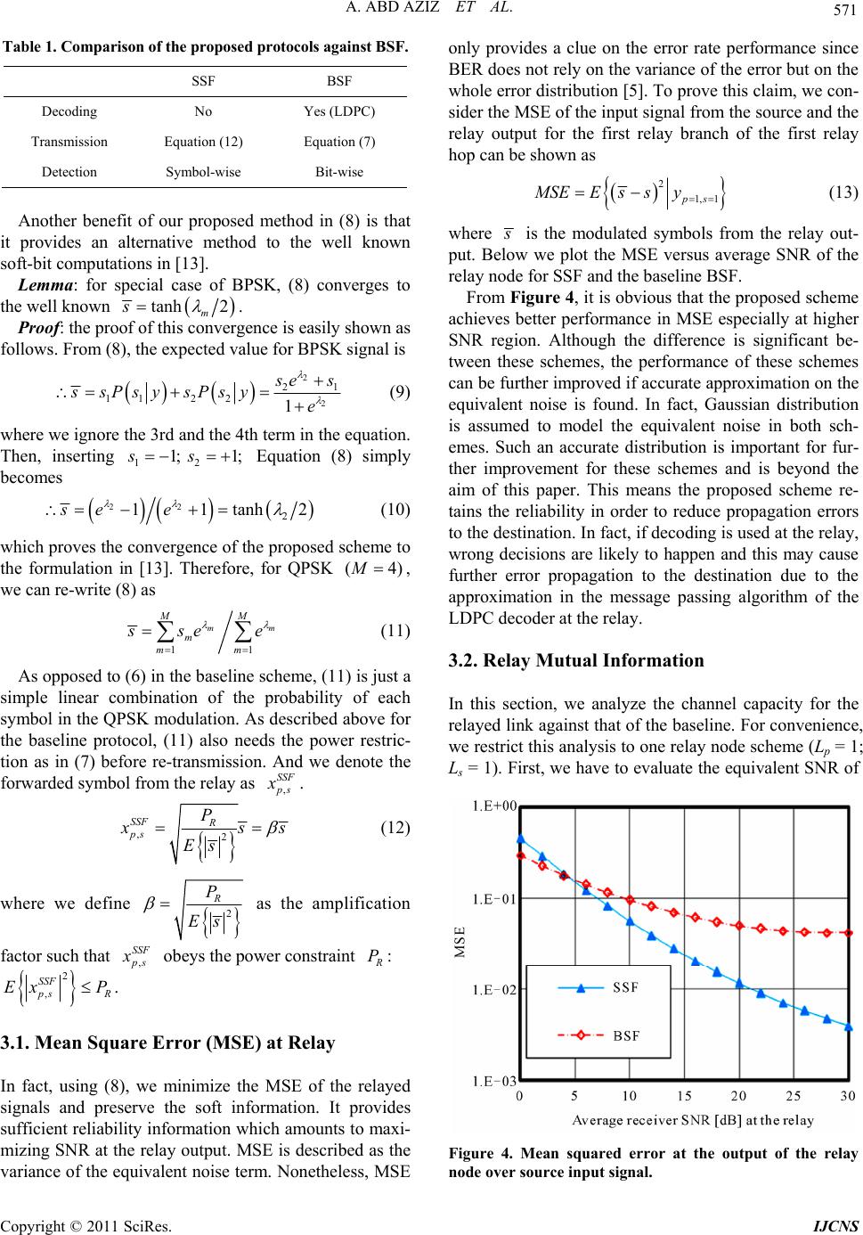 A. ABD AZIZ ET AL. 571 Table 1. Comparison of the proposed protocols against BSF. SSF BSF Decoding No Yes (LDPC) Transmission Equation (12) Equation (7) Detection Symbol-wise Bit-wise Another benefit of our proposed method in (8) is that it provides an alternative method to the well known soft-bit computations in [13]. Lemma: for special case of BPSK, (8) converges to the well known tanh 2 m s . Proof: the proof of this convergence is easily shown as follows. From (8), the expected value for BPSK signal is 2 2 2 112 211 s es ssPsysPsy e (9) where we ignore the 3rd and the 4th term in the equation. Then, inserting Equation (8) simply becomes 12 1; 1;ss 22 2 11tanhse e 2 ) (10) which proves the convergence of the proposed scheme to the formulation in [13]. Therefore, for QPSK (4M , we can re-write (8) as 11 m MM m mm m s se e (11) As opposed to (6) in the baseline scheme, (11) is just a simple linear combination of the probability of each symbol in the QPSK modulation. As described above for the baseline protocol, (11) also needs the power restric- tion as in (7) before re-transmission. And we denote the forwarded symbol from the relay as , SSF p s x . ,2 SSF R ps P x s Es s (12) where we define 2 R P Es as the amplification factor such that , SSF p s x obeys the power constraint R P: 2 , SSF p sR Ex P. 3.1. Mean Square Error (MSE) at Relay In fact, using (8), we minimize the MSE of the relayed signals and preserve the soft information. It provides sufficient reliability information which amounts to maxi- mizing SNR at the relay output. MSE is described as the variance of the equivalent noise term. Nonetheless, MSE only provides a clue on the error rate performance since BER does not rely on the variance of the error but on the whole error distribution [5]. To prove this claim, we con- sider the MSE of the input signal from the source and the relay output for the first relay branch of the first relay hop can be shown as 2 1, 1ps MSEEssy (13) where s is the modulated symbols from the relay out- put. Below we plot the MSE versus average SNR of the relay node for SSF and the baseline BSF. From Figure 4, it is obvious that the proposed scheme achieves better performance in MSE especially at higher SNR region. Although the difference is significant be- tween these schemes, the performance of these schemes can be further improved if accurate approximation on the equivalent noise is found. In fact, Gaussian distribution is assumed to model the equivalent noise in both sch- emes. Such an accurate distribution is important for fur- ther improvement for these schemes and is beyond the aim of this paper. This means the proposed scheme re- tains the reliability in order to reduce propagation errors to the destination. In fact, if decoding is used at the relay, wrong decisions are likely to happen and this may cause further error propagation to the destination due to the approximation in the message passing algorithm of the LDPC decoder at the relay. 3.2. Relay Mutual Information In this section, we analyze the channel capacity for the relayed link against that of the baseline. For convenience, we restrict this analysis to one relay node sch eme (Lp = 1; Ls = 1). First, we have to evaluate the equivalent SNR of Figure 4. Mean squared error at the output of the relay node over source input signal. Copyright © 2011 SciRes. IJCNS  572 A. ABD AZIZ ET AL. the relayed link. The received signal at the destination for one relay no de which is the second hop in series ( s = 2) can be shown in the following relation 1,21,2 1,11,2 1,2 1,2 11 ,1 1,2 1,2 11 ee e e ee mm j c mm D MM m mm M ps j j jc c MM mm yhxn hs n hs hs n (14) where c s in the first term is the symbol estimate of the original symbol from the source while the second term is the noise. After some algebraic manipulations, for one relay node scheme 1,1 , the instantaneous SNR at the destination can be expressed as R 2 2 1,2 2 1,2 2 22 1,2 21,2 1 2 1,2 2 2 1,2 20 1 e e e e c j c j c D M j j jc S M S j jc hEs hEs En hP hPN (15) where we let 1 em M m . Therefore, the average chan- nel capacity for the proposed scheme considering the relayed link is found by averaging over the channel gain distribution as follows 1,221,2 1,2 0 log 1d D D SSF Cp D (16) To illustrate the performance of the proposed scheme, we simulate it through Monte-carlo simulations for one relay node case which is shown in Figure 5. 4. Simulation Results This section presents some results of simulations under- taken to illustrate the performance of the proposed schemes in BER against the average SNR per bit in decibel (dB), 000 PN 1) for the direct link in various simulation setups. Receiving nodes are assumed to have the same average receive SNR and perfect CSI of the immediate links. All simulation works use the following parameters in Table 2 unless otherwise stated. In this simulation, for simplicity, we only consider blind coop- erative relaying schemes where relay nodes always re-transmit to the destination whether the signal is cor- rectly detected or contains errors. No automatic repeat request (ARQ) protocol is used to avoid the error propa- gation from the relay nodes to the destination. 4.1. Multihop Setup (Lp = 1; Ls = 1, 2 and 3) In this simulation, firstly we consider one relay branch ( p L with multiple hops. Figure 6 shows the BER versus average SNR in dB for the proposed schemes against the baseline BSF. The simulation results validate the derivation of the proposed symbol LLR using MLD criterion and show the performance improvement by SSF against the baseline BSF. In Figure 6, we observe that the combination of the soft symbol estimation technique and the proposed forwarding strategy outperforms the rest and provides large performance improvement at no decoding cost. When in ter-node channel is noisy, a relay node without a decoder is sufficient to provide BER per- formance improvement. SSF improves the BER curve around 2 dB margin against the baseline BSF for case s (1 p LL ;1) . The relative margin increases as the number of relay nodes slightly increases in comparison Figure 5. Average capacity of the relayed link at the desti- nation for the proposed scheme. Table 2. Simulation parameters. Information Bits 504 bits/packet Modulations QPSK Channel Model Quasi-static Rayleigh Fading Cha nnel Error Correct ing Code Regula r (3, 6) LDPC (1008, 504) Sum-Product Iteration 20 times Copyright © 2011 SciRes. IJCNS 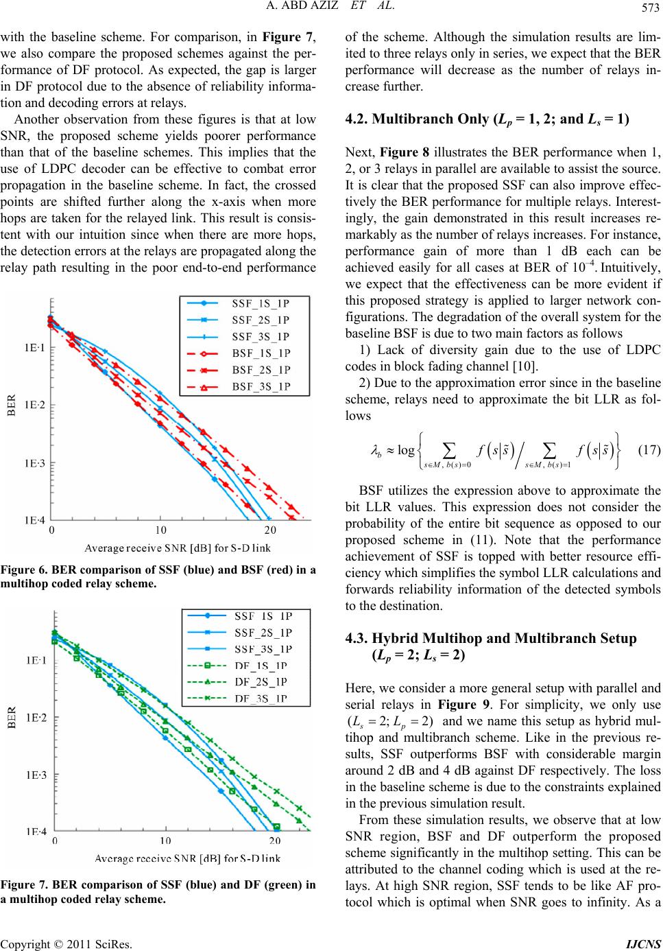 A. ABD AZIZ ET AL. 573 with the baseline scheme. For comparison, in Figure 7, we also compare the proposed schemes against the per- formance of DF protocol. As expected, the gap is larger in DF protocol due to the absence of reliability informa- tion and decoding errors at relays. Another observation from these figures is that at low SNR, the proposed scheme yields poorer performance than that of the baseline schemes. This implies that the use of LDPC decoder can be effective to combat error propagation in the baseline scheme. In fact, the crossed points are shifted further along the x-axis when more hops are taken for the relayed link. This result is consis- tent with our intuition since when there are more hops, the detection errors at the relays are propagated along the relay path resulting in the poor end-to-end performance Figure 6. BER comparison of SSF (blue) and BSF (red) in a multihop coded relay scheme. Figure 7. BER comparison of SSF (blue) and DF (green) in a multihop coded relay scheme. of the scheme. Although the simulation results are lim- ited to three relays only in series, we expect that the BER performance will decrease as the number of relays in- crease further. 4.2. Multibranch Only (Lp = 1, 2; and Ls = 1) Next, Figure 8 illustrates the BER performance when 1, 2, or 3 relays in parallel are available to assist the source. It is clear that the proposed SSF can also improve effec- tively the BER performance for multiple relays. Interest- ingly, the gain demonstrated in this result increases re- markably as the number of relays increases. For instance, performance gain of more than 1 dB each can be achieved easily for all cases at BER of 10–4. Intuitively, we expect that the effectiveness can be more evident if this proposed strategy is applied to larger network con- figurations. The degradation of the overall system for the baseline BSF is due to two main factors as follows 1) Lack of diversity gain due to the use of LDPC codes in block fading channel [10]. 2) Due to the approximation error since in the baseline scheme, relays need to approximate the bit LLR as fol- lows , () 0 , ()1 log bsMbs sMbs f ssf ss (17) BSF utilizes the expression above to approximate the bit LLR values. This expression does not consider the probability of the entire bit sequence as opposed to our proposed scheme in (11). Note that the performance achievement of SSF is topped with better resource effi- ciency which simplifies the symbol LLR calculations and forwards reliability information of the detected symbols to the destination. 4.3. Hybrid Multihop and Multibranch Setup (Lp = 2; Ls = 2) Here, we consider a more general setup with parallel and serial relays in Figure 9. For simplicity, we only use (2; 2 sp LL ) and we name this setup as hybrid mul- tihop and multibranch scheme. Like in the previous re- sults, SSF outperforms BSF with considerable margin around 2 dB and 4 dB against DF respectively. The loss in the baseline scheme is due to the constraints explained in the previous simulation result. From these simulation results, we observe that at low SNR region, BSF and DF outperform the proposed scheme significantly in the multihop setting. This can be attributed to the channel coding which is used at the re- lays. At high SNR region, SSF tends to be like AF pro- tocol which is optimal when SNR goes to infinity. As a Copyright © 2011 SciRes. IJCNS 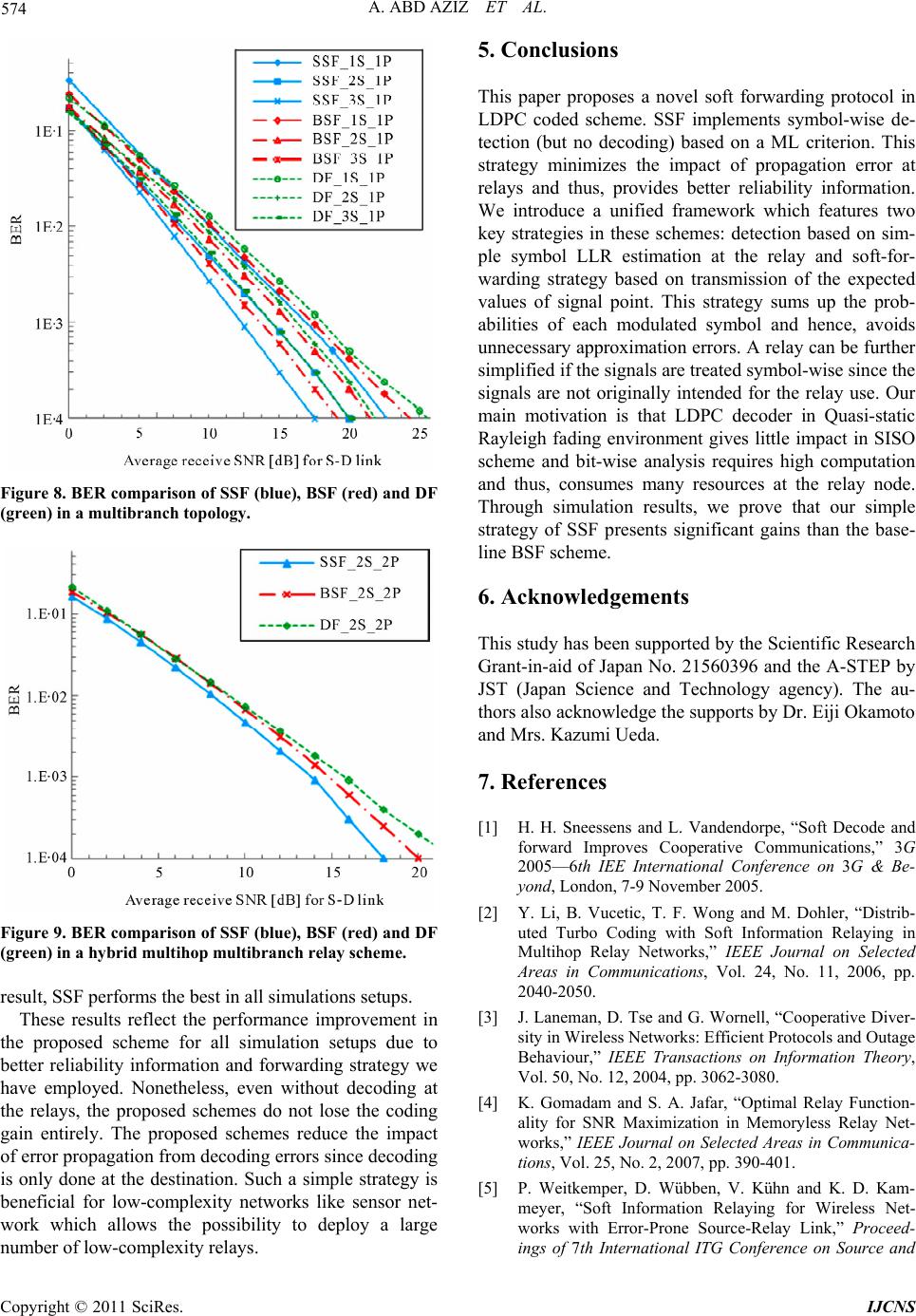 574 A. ABD AZIZ ET AL. Figure 8. BER comparison of SSF (blue), BSF (red) and DF (green) in a multibranch topology. Figure 9. BER comparison of SSF (blue), BSF (red) and DF (green) in a hybrid multihop multibranch relay scheme. result, SSF performs the best in all simulations setups. These results reflect the performance improvement in the proposed scheme for all simulation setups due to better reliability information and forwarding strategy we have employed. Nonetheless, even without decoding at the relays, the proposed schemes do not lose the coding gain entirely. The proposed schemes reduce the impact of error propagation from decoding errors since decoding is only done at the destination. Such a simple strategy is beneficial for low-complexity networks like sensor net- work which allows the possibility to deploy a large number of low-complexity relays. 5. Conclusions This paper proposes a novel soft forwarding protocol in LDPC coded scheme. SSF implements symbol-wise de- tection (but no decoding) based on a ML criterion. This strategy minimizes the impact of propagation error at relays and thus, provides better reliability information. We introduce a unified framework which features two key strategies in these schemes: detection based on sim- ple symbol LLR estimation at the relay and soft-for- warding strategy based on transmission of the expected values of signal point. This strategy sums up the prob- abilities of each modulated symbol and hence, avoids unnecessary approximation errors. A relay can be further simplified if the signals are treated symbol-wise since the signals are not originally intended for the relay use. Our main motivation is that LDPC decoder in Quasi-static Rayleigh fading environment gives little impact in SISO scheme and bit-wise analysis requires high computation and thus, consumes many resources at the relay node. Through simulation results, we prove that our simple strategy of SSF presents significant gains than the base- line BSF scheme. 6. Acknowledgements This study has been supported by the Scientific Research Grant-in-aid of Japan No. 21560396 and the A-STEP by JST (Japan Science and Technology agency). The au- thors also acknowled ge the sup por ts b y Dr. Eiji Ok amoto and Mrs. Kazumi Ueda. 7. References [1] H. H. Sneessens and L. Vandendorpe, “Soft Decode and forward Improves Cooperative Communications,” 3G 2005—6th IEE International Conference on 3G & Be- yond, London, 7-9 November 2005. [2] Y. Li, B. Vucetic, T. F. Wong and M. Dohler, “Distrib- uted Turbo Coding with Soft Information Relaying in Multihop Relay Networks,” IEEE Journal on Selected Areas in Communications, Vol. 24, No. 11, 2006, pp. 2040-2050. [3] J. Laneman, D. Tse and G. Wornell, “Cooperative Diver- sity in Wireless Networks: Efficient Protocols and Outage Behaviour,” IEEE Transactions on Information Theory, Vol. 50, No. 12, 2004, pp. 3062-3080. [4] K. Gomadam and S. A. Jafar, “Optimal Relay Function- ality for SNR Maximization in Memoryless Relay Net- works,” IEEE Journal on Selected Areas in Communica- tions, Vol. 25, No. 2, 2007, pp. 390-401. [5] P. Weitkemper, D. Wübben, V. Kühn and K. D. Kam- meyer, “Soft Information Relaying for Wireless Net- works with Error-Prone Source-Relay Link,” Proceed- ings of 7th International ITG Conference on Source and Copyright © 2011 SciRes. IJCNS  A. ABD AZIZ ET AL. Copyright © 2011 SciRes. IJCNS 575 Channel Coding, Ulm, 14-16 January 2008. [6] R. Thobaben, “On Distributed Codes with Noisy Relays,” In Proceedings of Asilomar Conference on Signals, Sys- tems & Computers, Pacific Grove, 26-29 October 2008. [7] A. Nosratinia and T. E. Hunter, “Diversity through Coded Cooperation,” IEEE Transactions on Wireless Commu- nications, Vol. 5, No. 2, February 2006, pp. 283-289. [8] T. Wang, A. Cano, G. Giannakis and N. Laneman, “High Performance Cooperative Demodulation with Decode- and-Forward Relays,” IEEE Transactions on Wireless Communications, Vol. 55, No. 7, 2007, pp. 1427- 1438. [9] A. Chakrabarti, A. de Baynast, A. Sabharwal and B. Aaz- hang, “Low Density Parity Check Codes for the Relay Channel,” IEEE Journal on Selected Areas in Communi- cations, Vol. 25, No. 2, 2007, pp. 280-291. [10] E. Biglieri, J. Proakis and S. Shamai, “Fading Channels: Information-Theoretic and Communications Aspects,” IEEE Transactions on Information Theory, Vol. 44, No. 6, 1998, pp. 2619-2692. [11] A. A. Aziz, Y. Iwanami and E. Okamoto, “Efficient Combining Technique with a Low-Complexity De- tect-and-Forward Relay for Cooperative Diversity Sch- eme,” Proceedings of TENCON 2009, Singapore City, 23-26 November 2009. [12] A. A. Aziz, Y. Iwanami and E. Okamoto, “On the Im- provement of Maximum Likelihood in Multiple Relay Systems,” Proceedings of WCNC, Sydney, 18-21 April 2010, pp. 1-6. [13] J. Hagenauer, E. Offer and L. Papke, “Iterative Decoding of Binary Block and Convolutional Codes,” IEEE Trans- actions on Information Theory, Vol. 42, No. 2, 1996, pp. 429-445. [14] V. Aue and R. Nuessgen, “Method for Generating Soft- Bit Information from Gray Coded Signals,” U.S. Patent 20040096007, May 2004. [15] K. S. Kim, K. Hyun, C. W. Yu, Y. O. Park, D. Yoon and S. K. Park, “General Log-Likelihood Ratio Expression and Its Implementation Algorithm for Gray-Coded QAM Signals,” ETRI Journal, Vol. 28, No. 3, 2006, pp. 291- 300.  576 A. ABD AZIZ ET AL. Appendix Derivation of Symbol LLR based on MLD and Expected value of Transmit Signal Point for the proposed relay function In this sub-section, we present the proposed detection and forwarding strategies employed at relay nodes. Without loss of generality, we consider a scheme with one relay node only ; thus, we remove the subscripts of the node relation for simplicity. Since calculating the exact bit LLR by using the conventional MLD is excessively exorbitant, there are a few ways proposed to approximate bit LLR values like in [14,15] whose aim is to avoid the high computation from the exact bit LLR expression. Although by using the con- ventional MLD the optimum performance can be achieved, the approach requires computation which grows exponentially with the constellation size of the modulation schemes. In this paper, we propose another simple approximation technique in order to avoid such complexity. Our proposed scheme requires symbol-wise computations and thus, avoids higher computations to evaluate every bit of the received signals. We define that the capital denotes the probability, and is the Probability Density Function (PDF) denoted in the following relation . For simplicity, QPSK modulation is considered which utilizes the Gray map- ping. We represent the complex symbols, ( 1;1) sp LL () ()Psps s ()Ps ()ps 12 (, ) m s bb as 1, , 3 4 where 1 and 2 correspond to the first and second bit of a symbol in the constellation. (0s b,0) b2 s(1, 0)s m (1,1), (0,1)s s is the m-th transmit signal, where is the constella- tion size for QPSK. For this system, the optimal detector will search the symbol such that it maximizes the a-posterior probability 1, ,mM(4)M () m Ps yy, the probability of receiving the transmit signal m s given that is re- ceived in the small region . We successively describe below two main steps of the proposed relaying strategy: y y Step 1: Calculate Symbol LLR Values The symbol LLRs can be shown as 111 221 331 441 log0, log , log , log e e e e Psyy Psyy Ps yyPsyy Ps yyPsyy Ps yyPsyy (18) where m , is the m-th symbol LLR in QPSK modulation, the transmit symbol 1 1, 2,3, 4m s is taken as the reference and its LLR value 1 is always equal to zero. Thus, there are three LLR values of 23 , and 4 . When is received, the symbol LLRs 23 y, and 4 are calculated to be plotted on the real straight line. This method simplifies the MLD rule to one-dimensional space only. If 4 is the largest on the real straight line, then 4 s is detected and if 23 , and 4 all have minus values on the real straight line, then 1 s is de- tected. For example, 4 is evaluated as follows 44 41 1 4 1 4 4 11 4 4 1 , glog , , g log , g log log ee ee ee e Ps yyPs yyPyy Ps yyPyy Psyy Ps Pyys Ps yy Ps yyPs Pyys pys Ps Ps pys pys pys 44 11 lo lo lo (19) where we let 44 loge1 P sPs . If the transition probability density is defined as 2 2 2 1exp 2 2 m yhs py m s , then we can re-write (19) as the following 44 4 4 1 22 41 22 22 414 2 log log expexp 22 1 2 e e pys pys yhs yhs yhs yhs (20) When the probability of the two symbols are the same 41 () ()14,Ps Ps then 441 log [()()]0. ePs Ps Thus, 2 and 3 are also evaluated in the same way as 4 . Step 2: Compute Expected Values from Symbol LLR Next we elaborate the transmission method from the relay to the destination. Since the computation of expec- tation values involves the soft symbols, we term this technique as soft modulation. In this paper we introduce another method of computing the expectation values which is another extension of our work in [12]. From Step 1, after the symbol LLR 123 ,, and 4 are calculated, the expected valu e of transmit sig nal poin t s can be evaluated in what follows. From (18)-(20), after some simplifications, we can obtain that 3 42 3 42 11 , , Ps y Ps yPs y eee Psy Psy Psy 1 (21) Since Copyright © 2011 SciRes. IJCNS  A. ABD AZIZ ET AL. Copyright © 2011 SciRes. IJCNS 577 3 24 1111 1Psy ePsy ePsy ePsy 3 42 3 24 1122 33 44 4321 1 11 11 1 1 mmmm M mm m MM MM mm mm mm s sPsy sPsy sPsysPsy sesese ssPs y eee seese e (24) (22) Then, 3 24 3 22 33 24 3 42 1 2 3 4 11 1 1 1 Psyee e Ps yeeee Ps yeeee Ps yeeee 4 4 (23) As opposed to the earlier methods, we propose a sim- ple strategy to utilize soft forwarding at the relay node. After computing the symbol LLR values by using (18)-(20), th e expected value of signal point from (2 4) is sent by relays to the destination according to the power limitations at the relays. Therefore, the expectation values for one QPSK sym- bol can simply be computed as |