 Materials Sciences and Applicatio ns, 2011, 2, 1322-1330 doi:10.4236/msa.2011.29180 Published Online September 2011 (http://www.SciRP.org/journal/msa) Copyright © 2011 SciRes. MSA Characterization of Porosity in a Laser Sintered MMCp Using X-Ray Synchrotron Phase Contrast Microtomography Emmanuelle Girardin1, Chiara Renghini2,3, Jack Dyson1, Vittorio Calbucci1, Francesca Moroncini1, Gianni Albertini1.4 1Università Politecnica delle Marche, Dipartimento di Fisica e Ingegneria dei Materiali e del Territorio, Via Brecce Bianche, Ancona, Italy; 2Università Politecnica delle Marche, Dipartimento SAIFET—Sezione di Scienze Fisiche—Via Brecce Bianche, Ancona, Italy; 3Istituto Nazionale di Biostrutture e Biosistemi—Consorzio Interuniversitario—Viale Medaglie d’Oro 305, Roma, Italy; 4CNISM (Consorzio Nazionale Interuniversitario per le Scienze fisiche della Materia), Italy. Email: e.girardin@alisf1.univpm.it Received April 14th, 2011; revised May 16th, 2011; accepted June 3rd, 2011. ABSTRACT Direct Laser Sintering (DSL), a technology enab ling the production of dense metal components directly from 3D CAD data, was used for the first time to produce a Metal Matrix Composite (MMCp) based on Al-Si-Cu alloy in view of its application in different fields, in particular for aeronautics. The porosity of the material obtained so was investigated by using optical and electron microscopy and, in particular, X-ray computed microtomography techniques. DSL is a unique technique to produce complex components in an economical way while computed microtomography is a unique technique to evaluate the porosity and pore and cracks distribution in a not destructive way. A near homogeneous dis- tribution of the porosity and pore sizes was observed both comparing different regions of the same specimen and also by comparing different samples obtained by using the same DLS production method. A quantitative analysis of the damage in the composite is also reported. Keywords: Metal Matrix Composite, Direct Laser Sintering, X- Ray Synchrotron, Computed Microtomography, Porosity 1. Introduction Direct Laser Sintering (DLS) is a technology enabling to produce dense metal components, directly from 3D CAD data. The quality of the product is comparable to that from a good investment casting, while the mechanical properties are comparable to those of a cast or machined part [1]. The application field of DLS is very wide as the so-ob- tained components can be used in place of almost any conventionally manufactured part, either machined or cast. In addition, the greater component complexity and feature richness, the greater the economy in production. Current applications concern subjects so different as Formula 1, Aerospace, Medical devices and Tooling. In particular, DLS technology can be used in Formula 1 and Aerospace industry not only to produce complex and structurally challenging parts made of various materials, but also it can offer lead times unachievable with other methods. DLS enables the production of very strong but light- weight components, also containing hollows or intelli- gent internal structures. DLS is also unique to combine different parts into a single one, thus obtaining complex components, making them lighter and potentially im- proving their functionality and strength. The materials submitted to DLS range from steels to non-ferrous materials and titanium [1-7]. Some applica- tions are also reported for composites, although, at our knowledge, only few cases concern Metal Matrix Com- posites (MMC). Some examples can be found on WC- Co/Cu composites [8,9], iron-SiC [10], (Al, Si, Mg)-SiC [11], Cu based alloy reinforced with Ni particles [12], (Fe,Ni)-TiC [13]. With the recent development of new three-dimensional (3D) characterization tools, a clear, accurate, and quanti- tative analysis of MMCs can be obtained. Several tech- niques have been used for visualization of microstruc- tures in 3D. Serial sectioning techniques using mechani- cal polishing coupled with optical microscopy [14,15] or 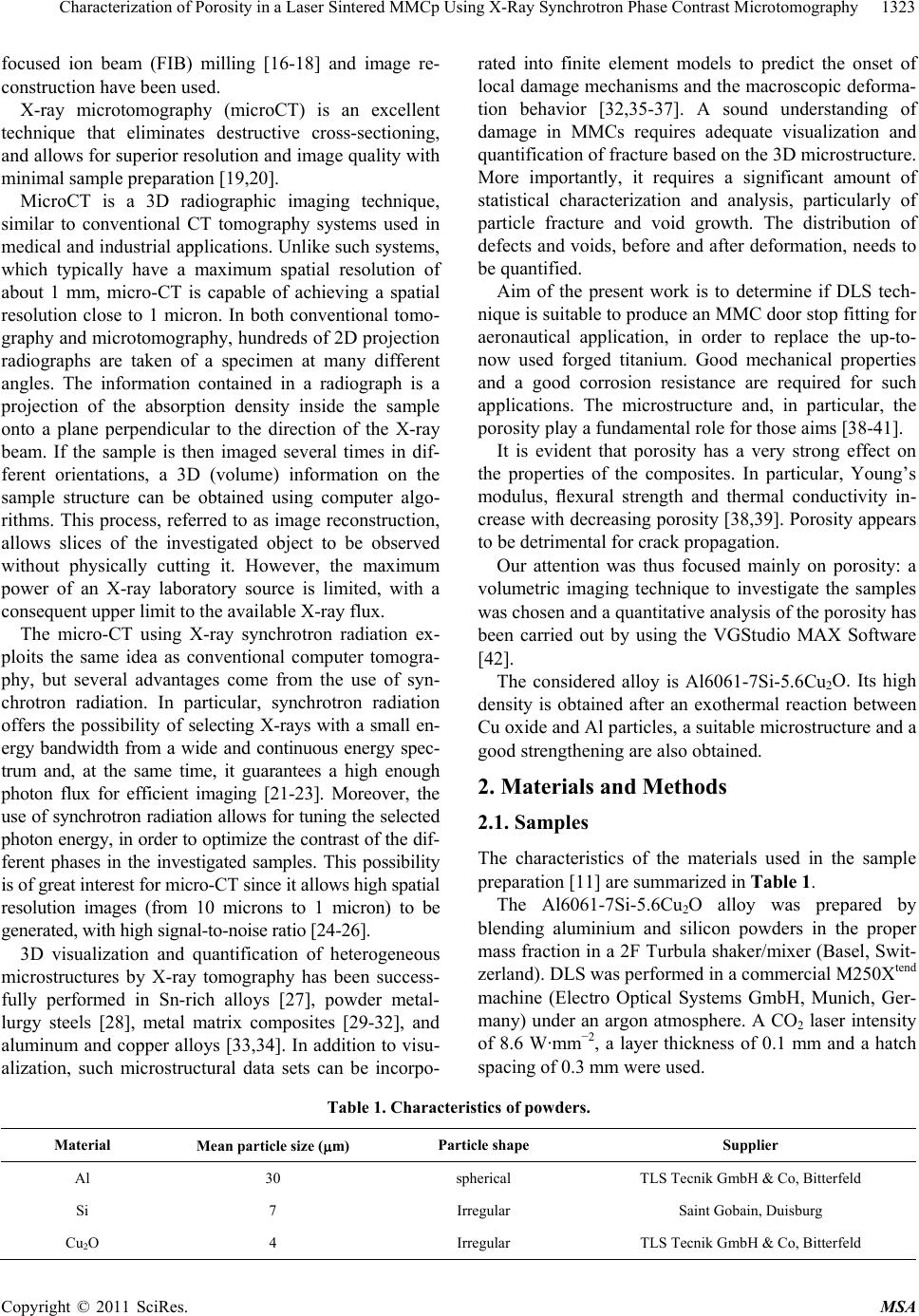 Characterization of Porosity in a Laser Sintered MMCp Using X-Ray Synchrotron Phase Contrast Microtomography1323 focused ion beam (FIB) milling [16-18] and image re- construction have been used. X-ray microtomography (microCT) is an excellent technique that eliminates destructive cross-sectioning, and allows for superior resolution and image quality with minimal sample preparation [19,20]. MicroCT is a 3D radiographic imaging technique, similar to conventional CT tomography systems used in medical and industrial applications. Unlike such systems, which typically have a maximum spatial resolution of about 1 mm, micro-CT is capable of achieving a spatial resolution close to 1 micron. In both conventional tomo- graphy and microtomography, hundreds of 2D projection radiographs are taken of a specimen at many different angles. The information contained in a radiograph is a projection of the absorption density inside the sample onto a plane perpendicular to the direction of the X-ray beam. If the sample is then imaged several times in dif- ferent orientations, a 3D (volume) information on the sample structure can be obtained using computer algo- rithms. This process, referred to as image reconstruction, allows slices of the investigated object to be observed without physically cutting it. However, the maximum power of an X-ray laboratory source is limited, with a consequent upper limit to the available X-ray flux. The micro-CT using X-ray synchrotron radiation ex- ploits the same idea as conventional computer tomogra- phy, but several advantages come from the use of syn- chrotron radiation. In particular, synchrotron radiation offers the possibility of selecting X-rays with a small en- ergy bandwidth from a wide and continuous energy spec- trum and, at the same time, it guarantees a high enough photon flux for efficient imaging [21-23]. Moreover, the use of synchrotron radiation allows for tuning the selected photon energy, in order to optimize the contrast of the dif- ferent phases in the investigated samples. This possibility is of great interest for micro-CT since it allows high spatial resolution images (from 10 microns to 1 micron) to be generated, with high signal-to-noise ratio [24-26]. 3D visualization and quantification of heterogeneous microstructures by X-ray tomography has been success- fully performed in Sn-rich alloys [27], powder metal- lurgy steels [28], metal matrix composites [29-32], and aluminum and copper alloys [33,34]. In addition to visu- alization, such microstructural data sets can be incorpo- rated into finite element models to predict the onset of local damage mechanisms and the macroscopic deforma- tion behavior [32,35-37]. A sound understanding of damage in MMCs requires adequate visualization and quantification of fracture based on the 3D microstructure. More importantly, it requires a significant amount of statistical characterization and analysis, particularly of particle fracture and void growth. The distribution of defects and voids, before and after deformation, needs to be quantified. Aim of the present work is to determine if DLS tech- nique is suitable to produce an MMC door stop fitting for aeronautical application, in order to replace the up-to- now used forged titanium. Good mechanical properties and a good corrosion resistance are required for such applications. The microstructure and, in particular, the porosity play a fundamental role for those aims [38-41]. It is evident that porosity has a very strong effect on the properties of the composites. In particular, Young’s modulus, flexural strength and thermal conductivity in- crease with decreasing porosity [38,39]. Porosity appears to be detrimental for crack propagation. Our attention was thus focused mainly on porosity: a volumetric imaging technique to investigate the samples was chosen and a quantitative analysis of the porosity has been carried out by using the VGStudio MAX Software [42]. The considered alloy is Al6061-7Si-5.6Cu2O. Its high density is obtained after an exothermal reaction between Cu oxide and Al particles, a suitable microstructure and a good strengthening are also obtained. 2. Materials and Methods 2.1. Samples The characteristics of the materials used in the sample preparation [11] are summarized in Table 1. The Al6061-7Si-5.6Cu2O alloy was prepared by blending aluminium and silicon powders in the proper mass fraction in a 2F Turbula shaker/mixer (Basel, Swit- zerland). DLS was performed in a commercial M250Xtend machine (Electro Optical Systems GmbH, Munich, Ger- many) under an argon atmosphere. A CO2 laser intensity of 8.6 W·mm−2, a layer thickness of 0.1 mm and a hatch spacing of 0.3 mm were used. Table 1. Characteristics of powders. Material Mean particle size (m) Particle shape Supplier Al 30 spherical TLS Tecnik GmbH & Co, Bitterfeld Si 7 Irregular Saint Gobain, Duisburg Cu2O 4 Irregular TLS Tecnik GmbH & Co, Bitterfeld Copyright © 2011 SciRes. MSA 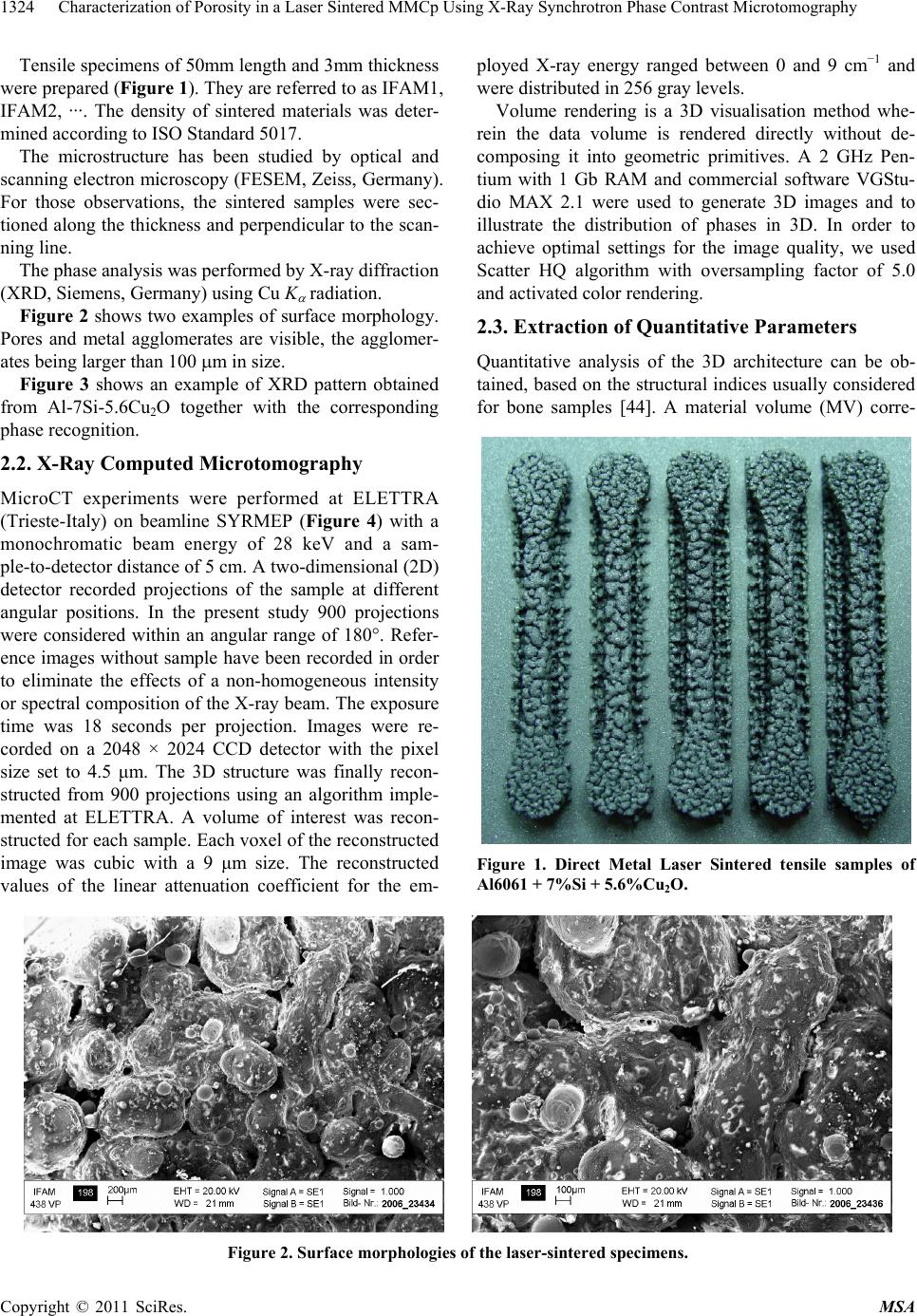 Characterization of Porosity in a Laser Sintered MMCp Using X-Ray Synchrotron Phase Contrast Microtomography 1324 Tensile specimens of 50mm length and 3mm thickness were prepared (Figure 1). They are referred to as IFAM1, IFAM2, ···. The density of sintered materials was deter- mined according to ISO Standard 5017. The microstructure has been studied by optical and scanning electron microscopy (FESEM, Zeiss, Germany). For those observations, the sintered samples were sec- tioned along the thickness and perpendicular to the scan- ning line. The phase analysis was performed by X-ray diffraction (XRD, Siemens, Germany) using Cu K radiation. Figure 2 shows two examples of surface morphology. Pores and metal agglomerates are visible, the agglomer- ates being larger than 100 m in size. Figure 3 shows an example of XRD pattern obtained from Al-7Si-5.6Cu2O together with the corresponding phase recognition. 2.2. X-Ray Computed Microtomography MicroCT experiments were performed at ELETTRA (Trieste-Italy) on beamline SYRMEP (Figure 4) with a monochromatic beam energy of 28 keV and a sam- ple-to-detector distance of 5 cm. A two-dimensional (2D) detector recorded projections of the sample at different angular positions. In the present study 900 projections were considered within an angular range of 180°. Refer- ence images without sample have been recorded in order to eliminate the effects of a non-homogeneous intensity or spectral composition of the X-ray beam. The exposure time was 18 seconds per projection. Images were re- corded on a 2048 × 2024 CCD detector with the pixel size set to 4.5 μm. The 3D structure was finally recon- structed from 900 projections using an algorithm imple- mented at ELETTRA. A volume of interest was recon- structed for each sample. Each voxel of the reconstructed image was cubic with a 9 μm size. The reconstructed values of the linear attenuation coefficient for the em- ployed X-ray energy ranged between 0 and 9 cm−1 and were distributed in 256 gray levels. Volume rendering is a 3D visualisation method whe- rein the data volume is rendered directly without de- composing it into geometric primitives. A 2 GHz Pen- tium with 1 Gb RAM and commercial software VGStu- dio MAX 2.1 were used to generate 3D images and to illustrate the distribution of phases in 3D. In order to achieve optimal settings for the image quality, we used Scatter HQ algorithm with oversampling factor of 5.0 and activated color rendering. 2.3. Extraction of Quantitative Parameters Quantitative analysis of the 3D architecture can be ob- tained, based on the structural indices usually considered for bone samples [44]. A material volume (MV) corre- Figure 1. Direct Metal Laser Sintered tensile samples of Al6061 + 7%Si + 5.6%Cu2O. Figure 2. Surface morphologies of the laser-sintered specimens. Copyright © 2011 SciRes. MSA 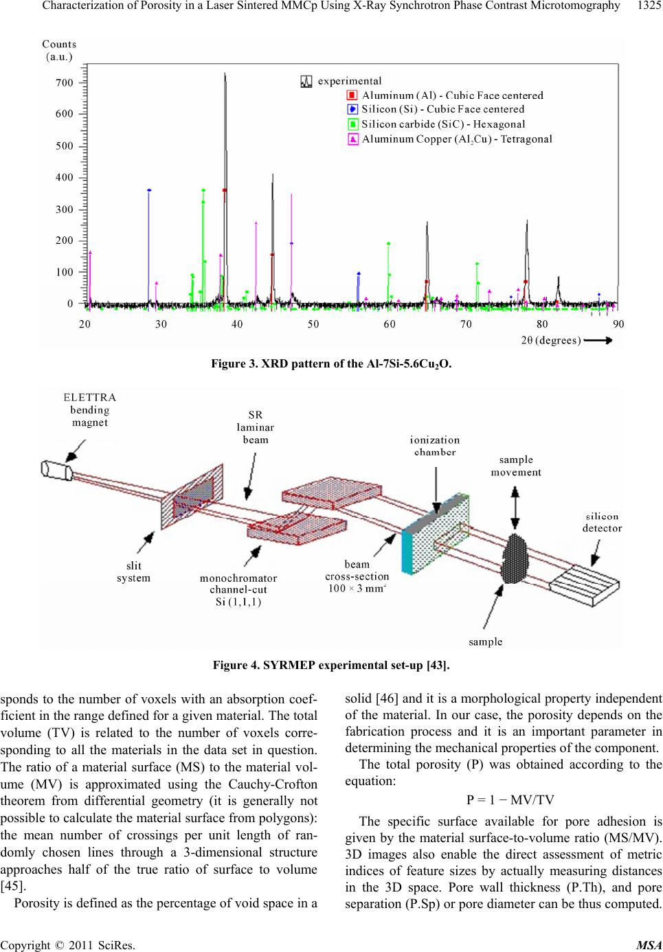 Characterization of Porosity in a Laser Sintered MMCp Using X-Ray Synchrotron Phase Contrast Microtomography1325 Figure 3. XRD pattern of the Al-7Si-5.6Cu2O. Figure 4. SYRMEP experimental set-up [43]. sponds to the number of voxels with an absorption coef- ficient in the range defined for a given material. The total volume (TV) is related to the number of voxels corre- sponding to all the materials in the data set in question. The ratio of a material surface (MS) to the material vol- ume (MV) is approximated using the Cauchy-Crofton theorem from differential geometry (it is generally not possible to calculate the material surface from polygons): the mean number of crossings per unit length of ran- domly chosen lines through a 3-dimensional structure approaches half of the true ratio of surface to volume [45]. Porosity is defined as the percentage of void space in a solid [46] and it is a morphological property independent of the material. In our case, the porosity depends on the fabrication process and it is an important parameter in determining the mechanical properties of the component. The total porosity (P) was obtained according to the equation: P = 1 − MV/TV The specific surface available for pore adhesion is given by the material surface-to-volume ratio (MS/MV). 3D images also enable the direct assessment of metric indices of feature sizes by actually measuring distances in the 3D space. Pore wall thickness (P.Th), and pore separation (P.Sp) or pore diameter can be thus computed. Copyright © 2011 SciRes. MSA  Characterization of Porosity in a Laser Sintered MMCp Using X-Ray Synchrotron Phase Contrast Microtomography 1326 The pore wall thickness depends on MS/MV and is cal- culated as P.Th = 2/(MS/MV). The mean number of pores per unit length (P.N) depends on MV/TV and is calculated as P.N = (MV/TV)/P.Th. The mean space (P.Sp) between pores depends on P.N and P.Th. It is calculated as P.Sp = (1/P.N) − P.Th. 3. Results 3.1. Microstructural Characterisation Three of the samples of Figure 1 were investigated by using X-ray Computed Microtomography. An example of the macroporous network and the microstructure of the investigated samples is reported in Figure 5. No sig- nificant differences existed in the internal microstructure among these samples. 3D quantitative parameters were calculated directly from 3D images to characterize the samples. This quanti- fication first required segmenting the different phases to separate them from the background. In these samples, such segmentation was easily performed by simple thre- sholding because the gray level histogram was clearly bimodal with a first peak corresponding to background and a second peak corresponding to the material of sam- ple (Figure 6). The main parameters obtained from those images are summarised in Table 2. 3.2. Pore Analysis A detailed examination of the porosity was carried out by using the spatial computational analysis techniques. The porosity computation was based on the calculation of a local pore map and was implemented using 3D Chamfer discrete distance [42]. The pore value is the diameter of the largest sphere completely included in a given portion of each the investigated samples. Figure 7 shows an example of central slices in the or- thogonal planes (xy, yz and xz) and a 3D volume recon- struction of the local pore sizes. Different thicknesses are plotted with different colors. After obtaining these maps, a quantitative analysis of the pore size distribution in the 3D microstructure was possible. In Figure 7, the presence of several cracks with di- mension in a range between 100 and 700 µm can be ob- served in addition to pores with diameters in a range be- tween 9 and 100 µm. Figure 8 shows the distribution of 3D pore size: these distributions were obtained by dividing the thickness Figure 5. 3D reconstruction of sub-volume of sample IFAM1 showing the microstructure. Figure 6. Gray Level Histogram of sample 1, showing the utilized threshold. Table 2. Summary of structural characteristics of the samples. Samples MV/TV Porosity (%) MS/MV P.Th (μm) P.Sp (μm) IFAM1 0.77 0.90 23.2 5.1 0.060 0.005 442.2 2.4 133.8 9.1 IFAM2 0.74 0.90 25.9 4.9 0.070 0.005 405.6 1.1 141.6 6.2 IFAM3 0.74 0.95 26.1 5.4 0.070 0.005 412.9 2.2 145.2 5.4 Copyright © 2011 SciRes. MSA  Characterization of Porosity in a Laser Sintered MMCp Using X-Ray Synchrotron Phase Contrast Microtomography1327 Figure 7. Example of central slices (a, b and c) in the or- thogonal planes (xy, yz and xz) and 3D volume (d) of the local pore size. The different thicknesses of pores are plot- ted with different colors. map in steps of 10 µm. From Figure 8 a large amount of micropores with ra- dius 0 < R < 20 μm is obtained. Lower amounts are ob- served at higher radius. The most of the radii are smaller than 55 μm, thus in- dicating that the sample porosity is mainly related to small pores. In order to assess the uniformity of the distribution, the percentages of holes with different sizes were considered in three regions of the sample IFAM2. The results are shown in Table 3, which reports the percent number of pores in the three most important ranges of radius: <10 μm, 10 - 20 μm, 20 - 30 μm. The distribution of pores size is uniform within the sample: in fact for each of the three intervals, the per- centage does not vary much from one area (down, centre, top) to another. The results reported in detail for sample IFAM2 are also representative of those obtained from the other two investigated samples. In this section we also report a quantitative analysis of damage in the composite. In particular, we have analyzed the void growth in the Al-Si-Cu alloy matrix in three dimensions. Figure 9 shows the distribution of 3D cracks size: these distributions were obtained by dividing the thickness map in steps of 50 µm. The distribution of the cracks is not the same in all the samples. In particular, the sample IFAM1 contains cracks with larger dimensions. Figure 8. Pore size distribution in the analyzed samples. Copyright © 2011 SciRes. MSA  Characterization of Porosity in a Laser Sintered MMCp Using X-Ray Synchrotron Phase Contrast Microtomography 1328 Table 3. Per cent porosity for each radius range. R < 10 10 < R < 20 20 < R < 30 Total number of pores Top of the sample 53.6% 24.0% 10.9% 6619 Centre 55.5% 24.3% 9.8% 7661 Down 56.3% 23.8% 10.8% 6850 Average porosity 55.2% 24.0% 10.5% 21130 Figure 9. Crack size distribution in the analyzed samples. 4. Conclusions For the first time, DLS has been used for the Al-Si-Cu MMCp alloy. Porosity is an important parameter that influences the mechanical properties of the material, also in view of its application as a door stop fitting for aero- nautical needs. The results show that the porosity is distributed ho- mogeneously inside the samples both considering its global value and also considering the contributions com- ing from the different classes of voids of different sizes. In particular, a porosity of 25% ± 5% was obtained for all samples. The most of the pores have diameter not larger than 100 μm and the porosity is mostly due to a great quantity of small pores, with radius between 10 and 20 μm. The occurrence of cracks and their not homogeneous distribution in samples nominally submitted to the same treatments can indicate that the so far obtained structure is brittle. 5. Acknowledgments The authors acknowledge the ELETTRA User Office for kindly providing beam-time, and Dr. L. Rigon and Dr. L. Paccamiccio for the technical support during the experi- ments. The authors wish to acknowledge the EU Network of Excellence project Knowledge based Multicomponent Copyright © 2011 SciRes. MSA  Characterization of Porosity in a Laser Sintered MMCp Using X-Ray Synchrotron Phase Contrast Microtomography1329 Materials for Durable and Safe Performance (KMM-NoE) under the contract No. NMP3-CT-2004-502243. REFERENCES [1] Y. Tang, H. T. Loh, Y. S. Wong, J. Y. H. Fuh, L. Lu and X. Wang, “Direct Laser Sintering of a Copper-Based Al- loy for Creating Three-Dimensional Metal Parts,” Journal of Materials Processing Technology, Vol. 140, No. 1-3, 2003, pp. 368-372. doi:10.1016/S0924-0136(03)00766-0 [2] A. Simchi and H. Pohl, “Direct Laser Sintering of Iron- Graphite Powder Mixture,” Materials Science and Engi- neering A, Vol. 383, No. 2, 2004, pp. 191-200. doi:10.1016/j.msea.2004.05.070 [3] Y. Tang, J. Y. H. Fuh, H. T. Loh, Y. S. Wong and L. Lu, “Direct Laser Sintering of a Silica Sand,” Materials and Design, Vol. 24, No. 8, 2003, pp. 623-629. doi:10.1016/S0261-3069(03)00126-2 [4] D. D. Gu, and Y. F. Shen, “Influence of Phosphorus Ele- ment on Direct Laser Sintering of Multicomponent Cu- Based Metal Powder,” Metallurgical and Materials Transactions B, Vol. 37B, No. 6, 2006, pp. 967-977. doi:10.1007/BF02735019 [5] A. Simchi, “The Role of Particle Size on the Laser Sin- tering of Iron Powder,” Metallurgical and Materials Transactions B, Vol. 35B, No. 5, 2004, pp. 937-948. doi:10.1007/s11663-004-0088-3 [6] T. Traini, C. Mangano, R. L. Sammons, Mangano, A. Macchi and A. Piattelli, “Direct Laser Metal Sintering as a New Approach to Fabrication of an Isoelastic Function- ally Graded Material for Manufacture of Porous Titanium Dental Implants,” Dental Materials, Vol. 24, No. 11, 2008, pp. 1525-1533. doi:10.1016/j.dental.2008.03.029 [7] L. Sabadin Bertol, W. Kindlein Júnior, F. Pinto da Silva and C. Aumund-Kopp, “Medical Design: Direct Metal Laser Sintering of Ti–6Al–4V,” Materials & Design, Vol. 31, No. 8, 2010, pp. 3982-3988. [8] D. D. Gu and Y. F. Shen, “Direct Laser Sintered WC- 10Co/Cu Nanocomposites,” Applied Surface Science, Vol. 254, No. 13, 2008, pp. 3971-3978. doi:10.1016/j.apsusc.2007.12.028 [9] D. D. Gu and Y. F. Shen, “WC–Co Particulate Reinforc- ing Cu Matrix Composites Produced by Direct Laser Sin- tering,” Materials Letters, Vol. 60, No. 29-30, 2006, pp. 3664-3668. doi:10.1016/j.matlet.2006.03.103 [10] C. S. Ramesha and C. K. Srinivas, “Friction and Wear Behavior of Laser-Sintered Iron–Silicon Carbide Com- posites,” Journal of Materials Processing Technology, Vol. 209, No.14, 2009, pp. 5429-5436. doi:10.1016/j.jmatprotec.2009.04.018 [11] A. Simchi and D. Godlinski, “Effect of SiC Particles on the Laser Sintering of Al–7Si–0.3Mg Alloy,” Scripta Materialia, Vol. 59, No. 2, 2008, pp. 199-202. doi:10.1016/j.scriptamat.2008.03.007 [12] D. D. Gu, Y. F. Shen and Z. Lu, “Microstructural Char- acteristics and Formation Mechanism of Direct Laser- Sintered Cu-Based Alloys Reinforced with Ni Particles,” Materials and Design, Vol. 30, No. 6, 2009, pp. 2099- 2107. doi:10.1016/j.matdes.2008.08.036 [13] A. Gåård, P. Krakhmalev and J. Bergström, “Microstruc- tural Characterization and Wear Behavior of (Fe,Ni)-TiC MMC Prepared by DMLS,” Journal of Alloys and Com- pounds, Vol. 421, No.1-2, 2006, pp. 166-171. [14] R. S. Sidhu and N. Chawla, “Three-Dimensional Micro- structure Characterization of Ag3Sn Intermetallics in Sn- Rich Solder by Serial Sectioning,” Materials Characteri- zation, Vol. 52, No. 8 ,2004, pp. 225-230. doi:10.1016/j.matchar.2004.04.010 [15] M. A. Dudek and N. Chawla, “Three-Dimensional (3D) Visualization of Reflow Porosity and Modeling of De- formation in Pb-Free Solder Joints,” Materials Charac- terization, Vol. 59, No. 4, 2008, pp. 1364-1368. doi:10.1016/j.matchar.2007.10.008 [16] A. J. Kubis, G. J. Shiflet and R. Hull, “Focused Ion-Beam Tomography,” Metallurgical and Materials Transactions, Vol. 35, No. 7, 2004, pp. 1935-1943. doi:10.1007/s11661-004-0142-4 [17] D. R. P. Singh, N. Chawla, and Y.-L. Shen, “Focused Ion Beam (FIB) Tomography of Nanoindentation Damage in Nanoscale Metal/Ceramic Multilayers,” Materials Char- acterization, Vol. 61, No. 4, 2010, pp. 481-488. doi:10.1016/j.matchar.2010.01.005 [18] F. Lasagni, A. Lasagni, E. Marks, C. Holzapfel, F. Muck- lich and H. P. Degischer, “Three-Dimensional Charac- terization of ‘as-cast’ and Solution-Treated AlSi12(Sr) Alloys by High-Resolution FIB Tomography,” Acta Ma- terialia, Vol. 55, No. 11, 2007, pp. 3875-3882. doi:10.1016/j.actamat.2007.03.004 [19] J. Baruchel, P. Bleuet, A. Bravin, P. Coan, E. Lima, A. Madsen, et al., “Advances in Synchrotron Hard X-Ray Based Imaging,” CR Physique, Vol. 9, No. 5-6, 2008, pp. 624-641. doi:10.1016/j.crhy.2007.08.003 [20] J. H. Kinney and M. C. Nichols, “X-Ray Tomographic Microscopy (XTM) Using Synchrotron Radiation,” An- nual Review of Materials Science, Vol. 22, 1992, pp. 121- 152. doi:10.1146/annurev.ms.22.080192.001005 [21] R. Cancedda, M. Mastrogiacomo, G. Bianchi, A. Derubeis, A. Muraglia and R. Quarto, “Bone Marrow Stromal Cells and the Use in Regenerating Bone,” Novartis Foundation Symposium, Vol. 249, 2003, pp. 133-143. [22] M. Marcacci, E. Kon, S. Zaffagnini, R. Giardino, M. Rocca, A. Corsi, A. Benvenuti, P. Bianco, R. Quarto, I. Martin and R. Cancedda, “Reconstruction of Extensive Long Bone Defects in Sheep Using Porous Hydroxyapa- tite Soinge,” Calcified Tissue International, Vol. 64, No. 1, 1999, pp. 83-90. doi:10.1007/s002239900583 [23] N. Kotobuki, K. Ioku, D. Kawagoe, H. Fujimori, S. Goto and H. Ohgushi, “Observation of Osteogenic Differentia- tion Cascade of Living Mesenchymal Stem Cells on Transparent Hydroxyapatite Ceramic,” Biomaterials, Vol. 26, No. 7, 2005, pp. 779-785. [24] E. N. Landis, E. N. Nagy and D. T. Keane, “Microstruc- ture and Fracture in Three Dimensions,” Engineering Fracture Mechanism, Vol. 70, No. 7-8, 2003, pp. 911- Copyright © 2011 SciRes. MSA  Characterization of Porosity in a Laser Sintered MMCp Using X-Ray Synchrotron Phase Contrast Microtomography Copyright © 2011 SciRes. MSA 1330 925. [25] M. Weyland and P. A. Midgley, “Electron Tomography,” Materials Today, Vol. 7, 2004, pp. 32-40. doi:10.1016/S1369-7021(04)00569-3 [26] M. Salomè, F. Peyrin, P. Cloetens, C. Odet, A. M. Laval- Jeantet, J. Baruchel and P. Spanne, “Synchrotron Radia- tion Microtomography System for the Analysis of Trabe- cular Bone Samples,” Medical Physics, Vol. 26, No. 10, 1999, pp. 2194-2204. [27] M. Dudek, L. Hunter, S. Kranz, J. J. Williams, S. H. Lau and N. Chawla, “Three-Dimensional (3D) Visualization of Reflow Porosity and Modeling of Deformation in Pb- Free Solder Joints,” Materials Characterization, Vol. 61, No. 4, 2009, pp. 433-439. doi:10.1016/j.matchar.2010.01.011 [28] N. Chawla, J. J. Williams, X. Deng and C. McClimon, “Three-Dimensional Characterization and Modeling of Porosity in PM Steel,” International Journal of Powder Metallurgy, Vol. 45, No. 2, 2009, pp. 19-27. [29] L. Babout, E. Maire, J. Y. Buffiere and R. Fougeres, “Characterization by X-Ray Computed Tomography of Decohesion, Porosity Growth and Coalescence in Model Metal Matrix Composites,” Acta Materialia, Vol. 49, No. 11, 2001, pp. 2055-2063. doi:10.1016/S1359-6454(01)00104-5 [30] A. Borbely, F. F. Csikor, S. Zabler, P. Cloetens and H. Biermann, “Three-Dimensional Characterization of the Microstructure of a Metal–Matrix Composite by Holoto- mography,” Materials Science and Engineering: A, Vol. 367, Vol. 1-2, 2004, pp. 40-50. [31] P. Kenesei, H. Biermann and A. Borbely “Structure– Property Relationship in Particle Reinforced Metal-Ma- trix Composites Based on Holotomography,” Scripta Materialia, Vol. 53, No. 7, 2005, pp. 787-791. doi:10.1016/j.scriptamat.2005.06.015 [32] F. A. Silva, J. J. Williams, B. R. Mueller, M. P. Hentschel, P. D. Portella and N. Chawla, “Three-Dimensional Mi- crostructure Visualization of Porosity and Fe-Rich Inclu- sions in SiC Particle-Reinforced Al Alloy Matrix Com- posites by X-Ray Synchrotron Tomography,” Metallur- gical and Materials Transactions, Vol. 41, No. 8, 2010, pp. 2121-2128. doi:10.1007/s11661-010-0260-0 [33] A. Weck, D. S. Wilkinson, E. Maire and H. Toda, “Visu- alization by X-Ray Tomography of Void Growth and Coalescence Leading to Fracture in Model Materials,” Acta Materialia, Vol. 56, No. 12, 2008, pp. 2919-2928. doi:10.1016/j.actamat.2008.02.027 [34] H. Toda, S. Yamamoto, M. Kobayashi, K. Uesugi and H. Zhang, “Direct Measurement Procedure for Three-Di- mensional Local Crack Driving Force Using Synchrotron X-Ray Microtomography,” Acta Materialia, Vol. 56, No. 20 ,2008, pp. 6027-6039. doi:10.1016/j.actamat.2008.08.022 [35] N. Chawla, V. V. Ganesh and B. Wunsch, “Three-Dimen- sional (3D) Microstructure Visualization and Finite Ele- ment Modeling of the Mechanical Behavior of SiC Parti- cle Reinforced Aluminum Composites,” Scripta Materi- alia, Vol. 51, No. 2, 2004, pp. 161-165. doi:10.1016/j.scriptamat.2004.03.043 [36] N. Chawla and K. K. Chawla, “Microstructure-Based Modeling of the Deformation Behavior of Particle Rein- forced Metal Matrix Composites,” Journal of Materials Science, Vol. 41, No. 3, 2006, pp. 913-925. doi:10.1007/s10853-006-6572-1 [37] N. Chawla, R. S. Sidhu and V. V. Ganesh, “Three-Di- mensional Visualization and Micro Structure-Based Modeling of Deformation in Particle-Reinforced Com- posites,” Acta Materialia, Vol. 54, No. 6, 2006, pp. 1541- 1548. doi:10.1016/j.actamat.2005.11.027 [38] A. R. Boccaccini, G. Ondracek, P. Mazilu and D. Win- delberg, “On the Effective Young’s Modulus of Elasticity for Porous Materials: Microstructure Modelling and Comparison between Calculated and Experimental Val- ues,” Journal of the Mechanical Behavior of Materials, Vol. 4, 1993, pp. 119-128. doi:10.1515/JMBM.1993.4.2.119 [39] M. Pavese, M. Valle and C. Badini, “Effect of Porosity of Cordierite Performs on Microstructure and Mechanical Strength of C4 Composites,” Journal of the European Ceramic Society, Vol. 27, 2007, pp. 131-141. doi:10.1016/j.jeurceramsoc.2006.05.080 [40] T. J. Ha, H. H. Park, E. S. Kang, S. Shin and H. H. Cho, “Variations in Mechanical and Thermal Properties of Mesoporous Alumina Thin Films Due to Porosity and Ordered Pore Structure,” Journal of Colloid and Interface Science, Vol. 345, No. 1, 2010, pp. 120-124. doi:10.1016/j.jcis.2010.01.028 [41] Y. H. Li, G. B. Rao, L. J. Rong and Y. Y. Li, “The Influ- ence of Porosity on Corrosion Characteristics of Porous NiTi Alloy in Simulated Body Fluid,” Materials Letters, Vol. 57, No. 2, 2002, pp. 448-451. doi:10.1016/S0167-577X(02)00809-1 [42] http://www.volumegraphics.com/ [43] http://www.elettra.trieste.it/ [44] D. Ulrich, B. Van Rietbergen, A. Laib and P. Ruegsegger, “Load Transfer Analysis of the Distal Radius from in-Vivo High-Resolution CT-Imaging,” Journal of Bio- mechanics, Vol. 32, No. 8, 1999, pp. 821-828. doi:10.1016/S0021-9290(99)00062-7 [45] A. M. Parfitt et al., “Bone Histomorphometry: Standardi- zation of Nomenclature, Symbols, and Units,” Journal of Bone and Mineral Research, Vol. 2, No. 3, 1987, pp. 595- 610. [46] C. A. Leon y Leon, “New Perspectives in Mercury Po- rosimetry,” Advances in Colloid and Interface Science, Vol. 76-77, 1998, pp. 341-372. doi:10.1016/S0001-8686(98)00052-9
|