World Journal of Engineering and Technology
Vol.04 No.03(2016), Article ID:71336,10 pages
10.4236/wjet.2016.43D019
Structural Design Optimization of a Vertical Axis Wind Turbine for Seismic Qualification and Lightweight
Young-Hyu Choi1*, Min-Gyu Kang2
1Department of Mechanical Engineering, Changwon National University, Changwon, Republic of Korea
2Department of Mechanical Design, Changwon National University, Changwon, Republic of Korea


Received: September 21, 2016; Accepted: October 13, 2016; Published: October 20, 2016
ABSTRACT
Recently, there is a growing interest in seismic qualification of ridges, buildings and mechanical equipment worldwide due to increase of accidents caused by earthquake. Severe earthquake can bring serious problems in the wind turbines and eventually lead to an interruption to their electric power supply. To overcome and prevent these undesirable problems, structural design optimization of a small vertical axis wind turbine has performed, in this study, for seismic qualification and lightweight by using a Genetic Algorithm (GA) subject to some design constraints such as the maximum stress limit, maximum deformation limit, and seismic acceleration gain limit. Also, the structural design optimizations were conducted for the four different initial design variable sets to confirm robustness of the optimization algorithm used. As a result, all the optimization results for the 4 different initial designs showed good agreement with each other properly. Thus the structural design optimization of a small vertical-axis wind turbine could be successfully accomplished.
Keywords:
Small Vertical-Axis Wind Turbine, Seismic Qualification, Response Spectrum Analysis, Structural Design Optimization, Genetic Algorithm

1. Introduction
Since the adoption of the UNFCC (United Nations Framework for Convention on Climate Change) in 1992, requiring each country to reduce green-house gases, extensive R & D efforts for new renewable energy have been exerted across the globe [1] [2]. With the wind power among other new renewable energy options drawing much attention for its economic feasibility and potential for energy production, a range of wind turbines have been developed. Should power generation units including wind turbines be damaged by any external force, electric power supply would go awry. Therefore, seismic qualification should be considered in designing a wind turbine operating normally even when natural disasters such as earthquakes occur [3] [4]. The present study draws on the FEM (Finite Elements Method) and GA (Genetic Algorithm) [5] for design optimization with intent to improve the seismic qualification and minimize the weight of small vertical axis wind turbines. To test the robustness of the GA-based design optimization, 4 different sets of initial design variables were applied and the consistency of the results was compared.
2. Seismic Qualification Analysis of Wind Turbines
2.1. FE Modeling and Equation of Motion
Figure 1 shows a 3D CAD model and an FE (Finite Element) model for a small vertical axis wind turbine for seismic qualification analysis. In this FE modelling, shell element was used for the wing turbine’s blades and poles, while solid element was used for the gearbox. This FE model comprised 20,001 nodal points, 6753 shell elements, and 5156 solid elements. The material for the turbine blades is ABS 1020 (Young’s modulus = 3 GPa, Poisson’s ratio = 0.35, density = 1070 kg/m3, yield strength = 55 MPa, and allowable stress = 38 MPa). The material for the pole and gearbox is steel (young’s modulus = 200 GPa, Poisson’s ratio = 0.3, density = 7850 kg/m3, yield strength = 250 MPa, and allowable stress = 175 MPa).
The FE model in Figure 1 shows a multi-DOF (Degree Of Freedom) structural vibration system that bears the seismic load. If a seismic load is converted to an equivalent inertia force imposed on the structure by the ground acceleration, the equation of motion for the n-DOF undamped structural vibration system bearing the seismic load is represented as follows.
 (1)
(1)
Here,  ,
,  and
and  denote mass-, damping- and stiffness-coefficient ma- trices of order n, respectively.
  is the DOF vector.
  is the seismic acceleration vector.
  is the excitation force acting direction vector.
2.2. Static and Seismic Analysis
1) Seismic response spectrum analysis
The seismic response spectrum analysis was performed as per the RRS of SSE 5% (Required Response Spectrum of Safe Shutdown Earthquake with 5% damping) prescribed in KBC 2009 [6] and ASCE 7-10 [7]-[9]. According to the seismic design standards, the peak ground acceleration required to generate the seismic acceleration spectrum input is . When the soil profile type is soft rock ground, the seismic coefficients (or the load maintenance coefficients) are
  and
and . When the seismic risk coefficient
  (return period = 100 years), the peak
 (a)
(a) (b)
(b)
Figure 1. 3D CAD model and FE model of the vertical axis wind turbine. (a) 3D CAD model; (b) FE model.
ground acceleration is . This corresponds to the seismic design category D. Figure 2(a) shows the RRS in horizontal and vertical directions.
The seismic spectrum response of a wind turbine structure represented in the Equation (1) is obtained with the spectrum-mode analysis [1] [10] [11], where the maximum
 (a)
(a) (b)
(b)
Figure 2. Applied load data for seismic analysis and wind load response analysis. (a) Seismic load data (Floor RRS of SSE-5% condition); (b) Wind load data.
seismic responses per single mode with high participation factors are determined, and then combined using the SRSS (Square Root of the Sum of the Squares) method to find the total response. The number of modes considered in the seismic response analysis is determined in the order of participation factors with the total modal mass accounting for more than 90% of the total mass of the structure. The ANSYS [12] for structural analysis was used to derive the maximum seismic stress ( ) and the maximum seismic deformation (
 ) from the results of the modal analysis and response spectrum analysis. The acceleration response gain (G) is calculated from the maximum response acceleration and the maximum input acceleration.
2) Static analysis to dead weight and wind load
The static analysis of the FE model in Figure 1 was carried out to solve the maximum stress ( ) and maximum deformation (
 ) of the wind turbine caused by the dead weight. Likewise, the FEM static analysis of the FE wind turbine model under the wind load was performed to calculate the maximum stress (
 ) and maximum deformation (
 ). The wind load imposed on the section of the wind turbine structure was applied to three segments defined by the height above the ground as in Figure 2(b).
3) Total stress and total deformation
The maximum stress and the maximum deformation determined by the foregoing seismic response analysis and static structural analysis were combined using the SRSS(Square Root of the Sum of the Squares) to yield the total stress ( ) and total deformation (
 ) as follows.
 (2)
(2)
For seismic qualification of the wind turbine, total stresses of the wind turbine components are compared with their allowable stresses.
3. Structural Design Optimization
3.1. Identification of Design Problem
The design optimization problem of the small wind turbine structure is to determine the best design variables that meet the seismic qualification while minimizing the weight of the wind turbine structure. As in Figure 3, the thickness of turbine blade ( ) and that of the pole (
 ,
,  ,
, ) were defined as the design variables. Different thickness settings were applied to the 3 segments of the pole defined by height. Table 1 outlines the ranges of design variables. The design variables are represented as discrete values, considering the standard dimensions of commercial products.
The design optimization problem of the wind turbine meeting the seismic qualification and minimizing the total weight of the structure was formulated as follows.
Find ; Design variable set.
To minimize ; Object function. (3)

Table 1. Design variables.

Figure 3. Design variables of the wind turbine.
Subject to ; Constraints. (4)
where, ; Acceleration response gain. (5)
Here,  is the object function.
  is the weight of the structure.
  is the SRSS (Square Root of Sum of Squares) value of the acceleration response gain in the horizontal and vertical directions.
  and
and  are the scaling constants respectively.
  is the weighting factor.
 ,
,  and
and  are the acceleration response gains in
 ,
,  and
and  directions, respectively.
  and
and  are the maximum total stress (
 ) and maximum total deformation (
 ), respectively.
 ,
,  and
and  are the allowable acceleration responses in horizontal (
 and
and ) and vertical (
 ) directions, respectively.
  and
and  are the allowable total stress and total deformation, respectively.
  is the peak ground seismic input acceleration.
  is the peak response acceleration of the structure by seismic load. The foregoing values were found with the seismic analysis using the commercial program ANSYS APDL [12]. In this design optimization, the weighting factor
  was 0.5. The allowable acceleration response gain was set at
 . The allowable stress
  and the allowable displacement
  were set at 37 MPa and 30 mm, respectively.
3.2. Genetic Algorithm
The GA (Genetic Algorithm) based optimization search program [5] was used for the design optimization. The FEM structure analysis was used to calculate the values defined as the object functions and constraints of the design problem. To consider both the object functions and constraints in GA, the fitness function and penalty function were defined as follows.
Fitness function: (6)
(6)
Penalty function: (7)
(7)
where,  is number of violation, and

is amount of violation with their weighting factors of ,
,  ,
,  ,
,  ,
,  ,
, .
.
Table 2 shows the input parameters for the GA.
3.3. Design Optimization Results
To test the robustness of the design optimization based on the genetic algorithm, each of 4 different initial designs underwent the design optimization, and then the results were comparatively analyzed. The 4 initial designs were as follows. ,
,  ,
,  ,
, .
.
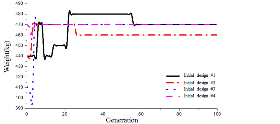
Figure 4 shows comparison of the convergence history of fitness and object functions in the design optimization search for each of 4 initial designs for checking robustness of the GA used.
Table 3 summarizes the design optimization results of 4 different initial designs. Here, each object function shows consistent results and the maximum deviation is 2%. Also, the design variables are consistent and the maximum deviation falls within 12.5%. Thus, this design optimization was proved to be robust enough.
Table 2. GA input parameters.
Table 3. Comparison of design optimization results for the 4 different initial designs.
 (a)
(a)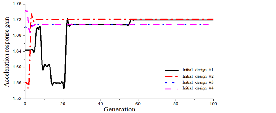 (b)
(b)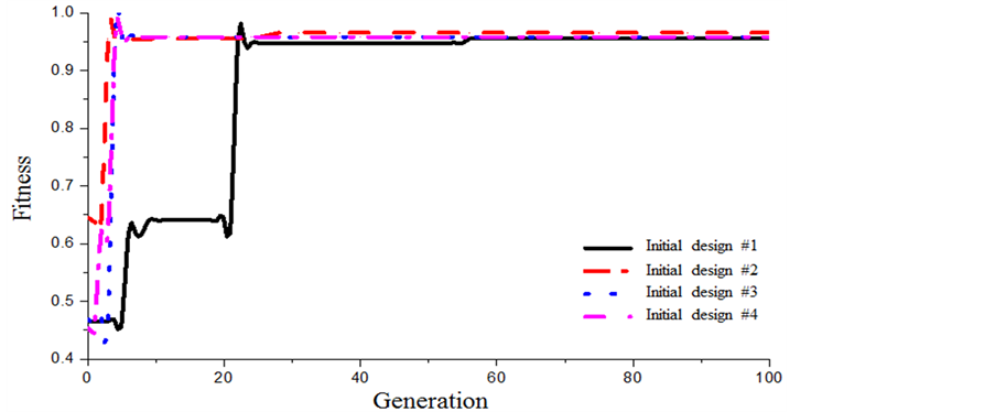 (c)
(c)
Figure 4. Comparison of objectives and fitness convergence of the 4 different initial designs. (a) Weight; (b) Acceleration response gain; (c) Fitness.
4. Conclusion
For the seismic qualification and lightweight of a small vertical-axis wind turbine structure, in this study, the GA-based structural design optimization was performed. First, the wind turbine structure was FE modelled. Then, the seismic load, static load and wind load specified in the seismic design criteria of KBC 2009 and ASCE 7 - 10 were applied to the seismic qualification analysis of the wind turbine. Next, the design optimization was performed to minimize the objective functions, i.e. the wind turbine’s structural weight and acceleration response gain, using the genetic algorithm. As the design constraints, the allowable total stress, allowable total deformation and allowable acceleration response gain values were selected. The design variables were the thickness of the wind turbine blades and that of the hollow pole. To verify the robustness of the optimum search algorithm, each of the 4 different initial designs underwent the design optimization. It was found the maximum deviations of the object functions and design variables fell within 2% and 12.5%, respectively, which supported the robustness of the proposed genetic algorithm and search. The present findings will be conducive to the effective seismic design of the vertical axis wind turbine by decreasing the time and cost of design and production.
Acknowledgements
“This research is financially supported by Changwon National University in 2016- 2017”.
Cite this paper
Choi, Y.-H. and Kang, M.-G. (2016) Structural Design Optimization of a Vertical Axis Wind Turbine for Seismic Qualification and Lightweight. World Journal of Engineering and Techno- logy, 4, 158-167. http://dx.doi.org/10.4236/wjet.2016.43D019
References
- 1. Choi, Y.H. and Hong, M.G. (2016) Seismic Qualification Analysis of a Vertical-Axis Wind Turbine. Journal of the Korean Society of Man-ufacturing Process Engineers, 15, 21-27. http://dx.doi.org/10.14775/ksmpe.2016.15.3.021
- 2. Islam, M.R., Mekhilef, S. and Saidur, R. (2013) Progress and Recent Trends of Wind Energy Technology. Renewable and Sustainable Energy Reviews, 21, 456-468. http://dx.doi.org/10.1016/j.rser.2013.01.007
- 3. Ishibashi, T., Tokuhiro, M. and Kojima, Y. (1996) Seismic Design in Electrical Control Technology. Fuji Electric Review, 42, 19-25.
- 4. Choi, J.S., Yun, D.J. and Kim, C.Y. (2014) A Case on Application and Performance-Based Seismic Design of Mechanical Systems. Proceedings of the Society of Air-Conditioning and Refrigerating Engineers of Korea 2014 Summer Conference, 990-992.
- 5. Lee, H.B., Oh, J.H., Oh, C.H. and Choi, Y.H. (2013) Structural Design Optimization of the Rotary Table of a Floor Type Boring Machine for Minimum Weight and Compliance by Using GA. Applied Mechanics and Materials, 271-272, 1421-1426. http://dx.doi.org/10.4028/www.scientific.net/AMM.271-272.1421
- 6. KBC 2009 (2009) Korean Building Code—Structural Korean Ministry of Land, Infrastructure and Transportation.
- 7. SEI/ASCE 7-10 Standard (2010) Minimum Design Loads for Buildings and Other Structures. The American Society of Civil Engineers.
- 8. Jeong, S.H. and Kim, J.K. (2011) Comparison of Provisions for Seismic Analysis Methods in ASCE 7-10 and KBC 2009. Proceedings of 2011 Workshop of the Earthquake Engineering Society of Korea, 251-262.
- 9. Midorikawa, M., Okawa, I., Iiba, M. and Teshigawara, M. (2004) Performance-Based Seismic Design Code for Buildings in Japan. Earthquake Engineering Seismology, 4, 15-25.
- 10. Han, S.U., Ahn, J.T., Lee, K.C. and Han, S.H. (2012) Theoretical Seismic Anal-ysis of Butterfly Valve for Nuclear Power Plant. Transactions of the Korean Society of Mechanical Engineers—A, 36, 1009-1015. http://dx.doi.org/10.3795/KSME-A.2012.36.9.1009
- 11. Wilson, E.L., Der Kiureghian, A. and Bayo, E.P. (1981) A Replacement for the SRSS Method in Seismic Analysis. Earthquake Engineering & Structural Dynamics, 9, 187-194. http://dx.doi.org/10.1002/eqe.4290090207
- 12. ANSYS Mechanical APDL Structural Analysis Guide (2013) ANSYS, Inc.