World Journal of Engineering and Technology
Vol.04 No.03(2016), Article ID:71329,9 pages
10.4236/wjet.2016.43D012
3D Software Technology, Applicable in Elaboration of the Spatial Face Gear Drives for Incorporation into Robot Systems
Emilia Abadjieva1,2, Valentin Abadjiev2, Detelina Ignatova2
1Faculty of Engineering Science, Graduate School of Engineering and Resource Science, Akita University, Akita, Japan
2Institute of Mechanics, Bulgarian Academy of Sciences, Sofia, Bulgaria


Received: July 6, 2016; Accepted: October 13, 2016; Published: October 20, 2016
ABSTRACT
The study treats a specific technological approach for the elaboration of small manufacturing series of highly precise hyperboloid gears with small module of the teeth and with not big dimensions of the gear mechanism. It is based on the application of the elaborated by authors mathematical models, algorithms and computer programs for synthesis upon a pitch contact point and upon a mesh region. A special feature of the established approach is the application of 3D software prototyping and 3D printing of the designed transmissions. The presented here models of the transmissions with crossed axes and face mated gears are indented for implementation into the driving of two type robots: bio-robot hand and walking robot with four insect-type legs.
Keywords:
Computer Synthesis, 3D Prototyping, 3D Printing, Skew-Axes Gears, Robot Systems

1. Introduction
This study is dedicated to a specific technological approach for small manufacturing series elaboration of highly precise hyperboloid gears with small module of the teeth and with not big dimensions of the gear mechanism. The presented here models of the transmissions with crossed axes and face mated gears are indented for implementation into the driving of two type robots: bio-robot hand [1]-[3] and walking robot with four insect-type legs [4] [5].
The future bio-robots will execute various complicated tasks by communicating with human users [1] [2]. Such robots will be equipped with anthropomorphic multi-fin- gered hands, which are similar to human hands. The main future purpose of such bio- robot’s hand is to replace the human presence, when doing dangerous tasks in the fields such as: industrial manufacturing, space, seabed and so on. One of the others future applications of the bio-robot hand are its use as prosthesis for handicapped people and also as a device for medical diagnostics. Hence, the requirement to such bio-robot hands is to obtain characteristics as accuracy and smoothness.
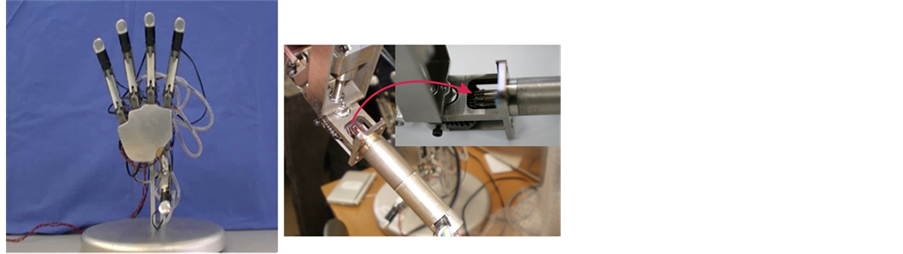
A five-fingered bio-robot hand (see Figure 1) [1]-[3] is developed in Kawasaki & Mouri Laboratory at Engineering Department of Gifu University. The aim of the robot hand is to be used as the standard platform for the study on dexterous grasping, manipulation of various types of objects and for diagnostics of tumors in female breast.
The research shown below is realized together with Prof. Kawasaki and Assoc. Prof. Mouri at Kawasaki& Mouri Laboratory at Gifu University-Japan.
Here are presented the accomplished by authors activates related to the improvement of exploitation properties of the mentioned bio-robot hand.
One of the tasks related to the mentioned above goal is to find out solution to the problems connected to the increment of the number of simultaneously contacting active tooth surfaces and also to create preconditions for controlling the backlash between mating gears, which are implemented into the fingers of this hand. This is achieved when a plane bevel gear (Figure 1(b)) is replaced with kinematically equivalent spatial gear drive of type Spiroid1 or Helicon.
Walking robots have been attempted since the beginning of the technology of transportation machinery with the aim to overpass the limits of wheeled systems by looking at legged solutions in nature [5]. Only since the last part of the 20-th century very efficient walking machines have been conceived, designed, and built with good performances that are suitable for practical applications carrying significant payload with relevant flexibility and versatility. A natural outdoor environment is the typical scenario for using legged robots. In such scenarios, these mobile machines exhibit many theoretical advantages over conventional vehicles that use wheels or tracks.
 (a) (b)
Figure 1. Model of robot hand: (a) whole hand; (b) bevel gear with straight teeth with ;
; ;
; ;
; .
.
The determining factors of the constructive architecture of the walking robot are: number of legs and their location to robot’s corpus, when its constructive configuration, kinematic scheme of the selected construction and the type of the drive built in the robot’s leg are defined.
For transmissions of the walking robot legs are used reductors, coupled with (direct current) DC or asynchronous motor. The high frequency of rotation of DC motors and the need to ensure maximum torques values of the actuators under the minimum speed require the application of reductors with high ratios (more than 250 - 300 to 6000). The application of high reduction gears is associated with creation of the mechanical joint actuators with optimal structural configuration, when the input angular velocity vector is perpendicular to the output angular velocity vector.
The idea of high gear ratio of the electromechanical driving of robot’s leg to be split in two by the plane gear (planetary or harmonic) and the high reduction hyperboloid gear of type Helicon, that are coupled, is suggested by Prof. V. Abadjiev and it is partially realized in the researched project between Institute of Mechanics-Bulgarian Academy of Sciences and Institute of Applied Mathematics-Russian Academy of Sciences in 1994. The result of the study is the synthesized and developed technological model of hyperboloid gear of type Helicon possessing 105 gear ratio. This gear is designed to be integrated into the leg transmissions of an insect-type robot with six legs [6] [7].
Similar solution of the actuating of joint of mobile robot with four legs is presented in reference (see Figure 2) [4]. There, the hyperboloid gears enclosed into the walking robot drives are Spiroid drives.
2. 3D Special Technology for Special Skew-Axes Gear Prototyping
The Spiroid and Helicon gear pairs belong to one of the most progressive and comparatively less applied in the engineering practice type of skew-axes gears.
These family of gears consists of two trademarked brands, Spiroid® and Helicon®, belong to Illinois Tool Works, Chicago, Illinois. This type of gearing, often referred to as “skew axis gearing”, operates on nonintersecting and nonparallel axes. Among progressive combinations of spatial gears (see Figure 3), Spiroid and Helicon gears occupy one essential place. The placement of the mesh region, geometry and technology of elaboration of these hyperboloid gear drives is the reason they are treated as a hybrid between hypoid gear sets and worm ones. For this reason, Spiroid and Helicon gear drives obtain constructive, technological and exploitation characteristics that make them suitable for application as power and kinematic gear mechanisms, which ensure the smooth and noiseless rotations transformation and with a possibility to realize rotations without a backlash between mating tooth surfaces. The Spiroid and Helicon pinion are the most common driving joints of these gear sets. The Spiroid and Helicon gears (crowns) are the driven joints, respectively. Gear ratios (the relation between the number of teeth of the gear (crown) Z2 and number of the teeth of the pinion Z1) are available ranging from 10 to more than 360 [7]-[11].

Figure 2. Insect leg model of insect-type robot: joint R1―motor power (W) 14, motor no load speed (rpm) 4800, motor stall torque (mNm) 105, Planetary reductor gear possessing ratio 246, joint angle (degrees) ±80; joint R2―motor power (W) 72, motor no load speed (rpm) 5300, motor stall torque (mNm) 510, Planetary reductor gear ratio 14, Spiroid reductor gear ratio 20.5, joint angle (degrees) +45: −90; joint R3―motor power (W) 26, motor no load speed (rpm) 5500, motor stall torque (mNm) 177, Planetary reductor gear ratio 14, Spiroid reductor gear 20.5, joint angle (degrees) +10: −135.
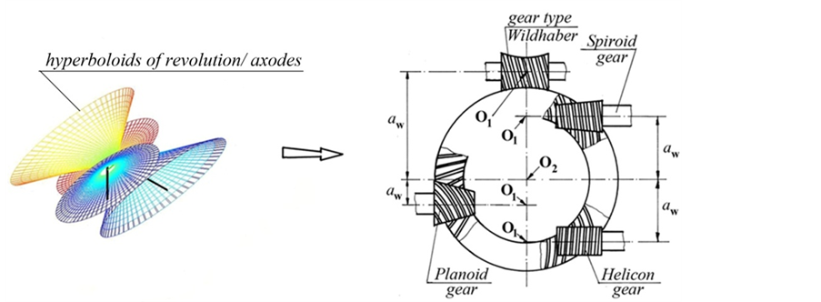
Figure 3. Family of skew-axes gears.
The studies, realized during the years at the Institute of Mechanics-Bulgarian Academy of Sciences [8]-[13], make possible three approaches for the synthesis of skew-axes gears (hyperboloid gears) to be formulated. These approaches are as follows:
Synthesis upon a pitch contact point;
Synthesis upon a mesh region;
Synthesis upon a pitch contact point and mesh region.
Computer programs for preliminary and optimization synthesis of Spiroid and Helicon gears [13] are developed, on the base of the created mathematical models and algorithms.
The third approach is used for the development of 3D software technology, which is applied in virtual and real prototyping of Spiroid and Helicon gears with special small sizes and small modules [3] [14]-[17].
The gear drives shown in Figures 4-7 are specially synthesized by choosing the optimal structure and geometrical characteristics and they are CAD modeled. From an exploitation view point these gear drives are suitable for integration into already existing robot hand, which will result in its technical precision.
 (a) (b)
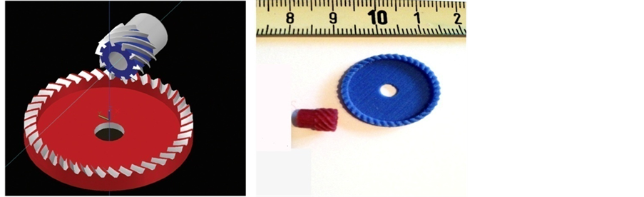
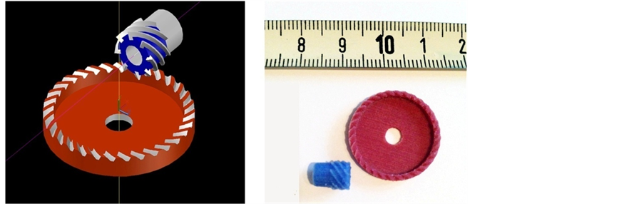
Figure 4. Helicon gear drive with offset 4 mm, gear ratio 40:10 (axial module 0. 5 mm): (a) 3D CAD model; (b) 3D printed model (the shown scale is in mm).
 (a) (b)
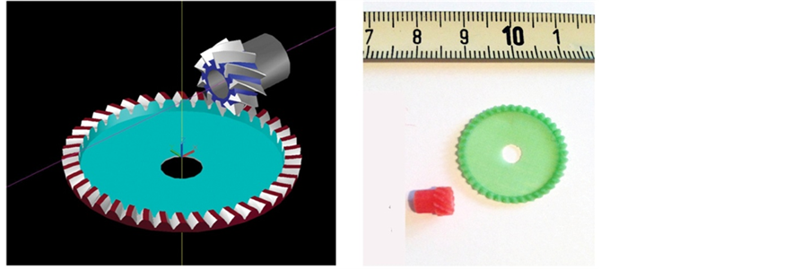
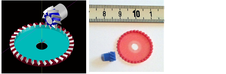
Figure 5. Spiroid gear drive with offset 4 mm, gear ratio 40:10 (axial module 0. 5 mm): (a) 3D CAD model; (b) 3D printed model (the shown scale is in mm).
 (a) (b)
Figure 6. Helicon gear drive with offset 3.25 mm, gear ratio 32:8 (axial module 0. 5 mm): (a) 3D CAD model; (b) 3D printed model (the shown scale is in mm).
 (a) (b)
Figure 7. Spiroid gear drive with offset 3.25 mm, gear ratio 32:8 (axial module 0. 5 mm): (a) 3D CAD model; (b) 3D printed model (the shown scale is in mm).
The novelty of this design solution is that developed Helicon and Spiroid gears have a boundary small gear ratio. This is a challenge both for their optimization synthesis and design in terms of their technical realization. The reason for this is that these gear pairs usually ensure rotations transformation with gear ratio more than 10.
The extreme difficulty of elaboration with available technical and technological device and the high manufacturing cost, define the reason to use 3D software technology for the elaboration of the above mention gear sets (see Figures 4-7).
The applied by authors 3D software technology include the following stages:
- Mathematical modeling for optimization synthesis of skew-axes gears upon a “pitch contact point”;
- Development of a mathematical model for synthesis upon a „mesh region“ (development of a 3D CAD model);
3D printing of the synthesized gear drives.
Figures 4(b)-7(b) illustrate the last two stages of the 3D software technology. The shown here software and 3D printed models are designed as alternative solutions of the plane bevel gear with straight teeth, which is one of the basic elements in the construction of bio-robot hand construction. The replacement of the plane bevel gear with this type of spatial gear mechanisms pursue not only the improvement the loading capacity of the transmission, by increasing the number of the simultaneously meshed tooth surfaces, but also the improvement of the noiseless and smoothness of the rotations transformation, through the effective regulation of the backlash.
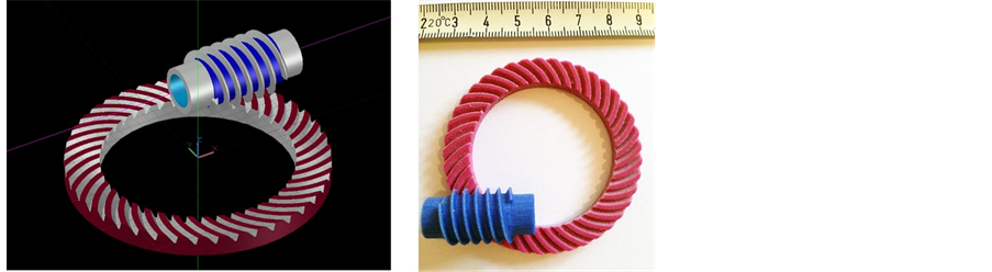
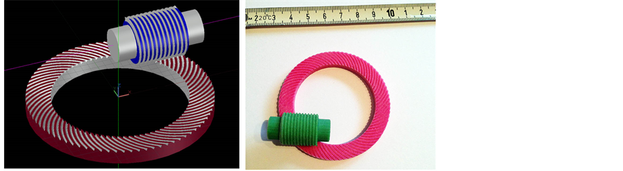
On the next figures two type gear drives of type Helicon (Figure 8 and Figure 9), with gear ratios of 20.5 and 76, are shown. Their modeling is realized by the commented here 3D software technology and with the application of 3D printing. These models are alternative designs of the Spiroid gears into the leg transmission of the insect-type robot (see Figure 2 [4]). The elaboration of two types Helicon reductors with different gear ratios is dictated by the idea of applying of the two types of locomotion control―for entire or limited self-breaking of the Helicon gear sets, when the torques applied on the shafts of the Helicon gears are created in the walking process of the robot.
The use of the 3D software technology is a guarantee of:
- Shortening of the cycle “innovative idea-innovative product” [16] [17];
- Impetus of the innovative strategies development and increasing the actual quality of the created prototypes by improving their accuracy and a fast realization of various modifications (variants) of a physical prototype;
 (a) (b)
Figure 8. Helicon gear drive with offset 17 mm, gear ratio 41:2 (axial module 0. 937 mm): (a) 3D CAD model; (b) 3D printed model (the shown scale is in mm).
 (a) (b)
Figure 9. Helicon gear drive with offset 17 mm, gear ratio 78:1 (axial module 0. 45 mm): (a) 3D CAD model; (b) 3D printed model (the shown scale is in mm).
- Impetus to the process of building a competitive environment;
- Stimulation of the inventive and innovative activity of engineers, designers and scientists.
3. Conclusions
The technology of 3D software synthesis is suitable to be applied for the studied gears, when they are dedicated for implementation into high precise devices, which are manufactured in small series. In this case the technology provides significant advantages in comparison with the classical gears cutting technology. The main reason is that the 3D technology is able to provide high precision in teeth generating, which is guarantee for practical realization of tooth contact with minor deviation from the given theoretical tooth contact. This is essential for the cases of Spiroid and Helicon gear sets with small gear ratios, i.e. when the Spiroid pinion and Helicon pinion respectively, has a large number of threads.
An essential problem, related to the 3D technology of manufacturing is the optimal choice of 3D printers and materials for the gear sets elaboration. The quality solution of these tasks is a guarantee for the optimal teeth strength, hardness of the active tooth surfaces and optimal smoothens.
Cite this paper
Abadjieva, E., Abad- jiev, V. and Ignatova, D. (2016) 3D Software Technology, Applicable in Elaboration of the Spatial Face Gear Drives for Incorporation into Robot Systems. World Journal of Engi- neering and Technology, 4, 91-99. http://dx.doi.org/10.4236/wjet.2016.43D012
References
- 1. Mouri, T., Kawasaki, H., Naganawa, S. and Muira, T. (2012) High Power Humanoid Robot Hand. Proceedings of RSJ2012, No RSJ2012AC202-3, Sapporo. (In Japanese)
- 2. Mouri, T., Endo, T. and Kawasaki, H. (2011) Review of Gifu Hand and Its Application. International Journal Mech. Based Design of Structures and Machines, Publisher Taylor and Francis, London, 210-228. http://dx.doi.org/10.1080/15397734.2011.550857
- 3. Abadjiev, V., Abadjieva E., Kawasaki, H. and Mouri, T. (2014) Computer Synthesis Approaches of Hyperboloid Gear Drives with Linear Contact. Journal of Theoretical and Applied Mechanics, Sofia, 44, 8-10.
- 4. Santos, P., Galvez, J., Estremara, J. and Gracia, E. (2003) SILO4. A True Walking Robot for the Comparative Study of Walking Machine Techniques. Robotics &Automation Magazine, 10, 23-32. http://dx.doi.org/10.1109/MRA.2003.1256295
- 5. Ignatova, D., Abadjieva E., Abadjiev, V. and Vatzkichev, A.L. (2014) Walking Robot Locomotion System Construction Conception. Journal of Theoretical and Applied Mechanics, Sofia, 44, 101-110.
- 6. Abadjiev, V. (1994) Aspects of Mathematical Modelling If Skew-Axes Gears Whose Tooth Surfaces Have a Linear Contact. Gearing and Transmissions, 2, 24-31.
- 7. Abadjiev, V. (2007) Gearing Theory and Technical Applications of Hyperboloid Mechanisms. Sc. D. Thesis, Institute of Mechanics, Bulgarian Academy of Sciences, Sofia, 309. (In Bulgarian)
- 8. Bohle, F. (1955) Spiroid Gears. A New Development in Gears of the Skew-Axis Type. Machinery, 62, 155-161.
- 9. Saari, O. (1956) The Mathematical Background of Spiroid Gears. Industrial Mathematical Series, 7, 131-144.
- 10. Nelson, W. (1961) Spiroid Gearing. Part 1—Basic Design Practices. Machine Design, 136- 144.
- 11. Razdevich, S. (2011) Dudley’s Handbook of Practical Gear Design and Manufacture. 2nd Edition, CRC Pres Taylor & Francis Group, 862.
- 12. Abadjieva, E., Abadjiev, V., Kawasaki, H. and Mouri, T. (2013) On the Synthesis of Hyperboloid Gears and Technical Applications. Proceedings of ASME 2013 International Power Transmissions and Gearing Conference, IDETC/CIE 2013, Portland.
- 13. Abadjieva, E., Abadjiev, V., Kawasaki, H. and Mouri, T. (2013) Application of the Gearing Primitives to Skew-Axes Gear Set Synthesis. Part 1: Principles of the Synthesis of Skew- Axes Gears upon a Pitch Contact Point. 12th International Congress on Theoretical and Applied Mechanics.
- 14. Abadjieva, E., Abadjiev, V., Kawasaki, H. and Mouri, T. (2013) Application of the Gearing Primitives to Skew-Axes Gear Set Synthesis. Part 2. Mathematical Model for Synthesis and Applications. 12th International Congress on Theoretical and Applied Mechanics.
- 15. Abadjiev, V., Abadjieva, E., Kawasaki, H., Mouri, T. and Petrova, D. (2014) Some Principles of Mathematical Modelling and Computer Synthesis of Hyperboloid Gears with a Conjugate Linear Contact. 2014 International Conference on Information Science, Electronics and Electrical Engineering, ISEEE 2014, Sapporo.
- 16. Abadjieva, E., Abadjieva, V. and Kawasaki, H. (2013) Pitch Configurations—An Innovative Solution to the Synthesis of Hyperboloid Gears. Part 1. Essence and Basic Characteristics of the Innovative Solutions, Advances in Education Research. The 2nd International Conference on Social Science and Education (ICSSE 2013), 47, 511-517.
- 17. Abadjieva, E., Abadjieva, V. and Kawasaki, H. (2013) Pitch Configurations—An Innovative Solution to the Synthesis of Hyperboloid Gears. Part 2. Analytical and Software Content of Pitch Configurations, Advances in Education Research. The 2nd International Conference on Social Science and Education (ICSSE 2013), 47, 518-525.
NOTES

1Spiroid and Helicon are registered marks of Illinois Tool Works, Chicago, Illinois.