World Journal of Engineering and Technology
Vol.04 No.03(2016), Article ID:71244,8 pages
10.4236/wjet.2016.43C011
Numerical Simulation of Fluid Structure Interaction between Flow and Steel Pipe Pile Platform in Deep Water
Wenyue Yan, Fengwu Lv
Department of Building Engineering, College of Civil Engineering, Tongji University, Shanghai, China


Received: May 1, 2016; Accepted: September 25, 2016; Published: September 28, 2016
ABSTRACT
In this paper, the two-way coupling of flow and steel pipe pile platform is simulated by ANSYS Workbench. Taking the construction platform in the deep water area of the Yangtze River Estuary as an example, the stress and deformation characteristics of the steel pipe pile platform under current force are analyzed in detail. As a result, it is suggested the platform piles should be arranged regularly and the connected node design of the platform structure should be strengthened to ensure the safety.
Keywords:
The Two-Way Coupling, Current Force, Pile Foundation Platform

1. Introduction
In deep water engineering, current force is one of the dominate load. However, the effect of structure on current force is mainly reflected in the projected area of the vertical direction of flow, shape of piles, pile spacing and so on, but the effect of structure displacement and deformation on the flow is ignored. Although this calculation method is easy to use in engineering, it’s not suitable for deep waters engineering. As the structure has a great influence on the flow of water in deep water because of the large deformation of the structure. It is significant to study the flow force of the structure in deep water, from the viewpoint of fluid structure interaction.
Some achievements have been obtained on studying fluid structure coupling by means of numerical simulation, with rapid development of calculation. Liu Yongji [1] used ANSYS to analyze the ratio of static water depth to the piles depth, composite elastic modulus of pile, ratio of thickness of hollow pile to the external diameter and influences of those to the fluid structure coupling. Lei Fan [2] used ANSYS CFX to study the vibration performance of the underwater flexible structures and mechanism performance under loads like current force and earthquake load, from the viewpoint of fluid structure interaction. Li Chao [3] used ANSYS Workbench to make a fluid solid interaction analysis on hydraulic floating wave power device. Zuo Shengrong [4] simulated the role of circular piers combined action of waves and uniform flow and analyzed the response of the piers.
Documents above mainly focus on numerical simulation of waves and fluid solid coupling between waves and simple structure model, but they seldom focus on coupling effect between water flow and structure, especially the two-way fluid structure coupling effect. In this paper, a two-way coupling of water flow and structure platform is simulated by using ANSYS Workbench, and the structure platform has nine piles with space angle and different pile spacing. The coupling effect between the steel pipe pile platform and the water flow is analyzed, which provides a reference for future engineering practice.
2. Theoretical Model and Control Equation
2.1. Equation of Fluid Solid Coupled System Field
Fluid is assumed to be free viscous, compressible and small perturbations, and fluid free surface is small fluctuation; and solid is assumed to be linear elastic. The finite element analysis method of the system constituted with the two ideal materials above has two types: Displacement-Displacement form and Displacement-Potentials form. As the Displacement-Potentials form is more efficient, it is highly used in engineering now. It means that the displacement ui is used as basic unknown quantity in the equation of solid domain, while the flow field pressure p is used as basic unknown quantity in the equation of fluid domain. The corresponding finite element expression format is called displacement-pressure  scheme for fluid solid coupling analysis [5].
1) Fluid Field
a) Fluid Field Equation
 . (1)
. (1)
where p is fluid pressure, co is sound velocity in fluid.
b) Fluid Boundary Conditions
Rigid fixed boundary:
 . (2)
. (2)
Free surface:
 . (3)
. (3)
2) Solid Field
a) Solid Field Equation
 . (4)
. (4)
where  is solid stress component,
  is solid displacement component,
  is solid volume force component,
  is solid mass density.
b) Solid Boundary Conditions
Force boundary:
 . (5)
. (5)
Displacement boundary:
 . (6)
. (6)
where  is known surface force component on solid,
  is known displacement components on solids.
3) Compatibility Conditions on the Fluid Solid Coupling Interface
a) Kinematic Condition
The normal velocity of the fluid solid interface should be continuous, which means
 . (7)
. (7)
where  is solid displacement vector,
  is fluid mass density.
b) Dynamitic Condition
Normal stress should be continuous on the interface of fluid solid interface, which means
 . (8)
. (8)
2.2. Turbulence Model
Considering the fluid as turbulent fluid, the additional turbulent equation is needed. In this paper, the standard  turbulence model is used.
Equation of fluctuating kinetic energy  is:
is:
 . (9)
. (9)
 is defined by
 . (10)
where  is eddy viscosity,
 . (11)
Equation of turbulent dissipation rate  is:
is:
 . (12)
Here,  is custom source term.
In  turbulence model,
  ,
,  ,
,  ,
,  ,
,  are empirical constants, whose values are given by [6].
3. Numerical Solution Method
The partial differential equations of fluid structure coupling shown above are quite complicated. It’s difficult to get the analytical solution of these equations. Therefore, the numerical analysis method is used to solve differential equations with a given boundary condition in this paper. Finite Element Method (FEM) in ANSYS Structure is used to solve the solid equations, while Finite Volume Method (FVM) in ANSYS CFX is used to solve the fluid equations.
Displacement-Pressure form is used as the finite element analysis model in this paper. The solid transmits its displacement to the fluid, considering the nodal displacement as boundary condition, the equation that uses the pressure of the flow field as the unknown variable can be solved. And then the flow transmits the boundary pressure to the solid, which considers nodal displacement as the unknown quantity of equations. After solving the solid equation, the nodal displacements are transmitted to the fluid, which will become the boundary condition of fluid field, and then circulate step by step until convergence.
This paper use ANSYS Workbench to carry out numerical simulation of fluid solid coupling. Workbench use ANSYS CFX and ANSYS Structure, respectively, to solve the fluid equation and solid equation in the same step, and then use MFX procedure of ANSYS to exchange the data on the fluid solid coupling surface. The solid and fluid fields are calculated according to the updated boundary conditions. The specific implementation thought is shown as Figure 1.
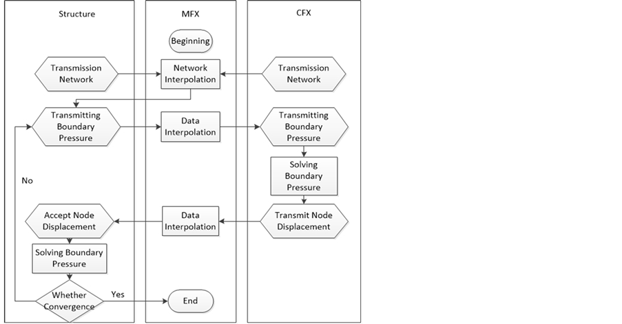
Figure 1. The realization of fluid structure coupling.
The coupling iteration number is controlled by the convergence accuracy. And it is taken as the convergence control criterion when RMS less than 1e−4 in this paper.
4. Case Analysis
A pier construction platform of a long-span cable bridge in the Yangtze River Estuary is selected as an example to simulate the two-way coupling between flow and steel pipe pile platform in deep water, whose flow velocity is 2 m/s and depth is 25 m.
The platform is a complex and irregular platform, whose length along the wave is 24 - 27 m, width is 12 m, and it is composed by 9 steel pipe piles, whose diameter is 1.4 m and thickness is 16 mm. What’s more there are space angles between flow and five of the nine piles, and the piles spacing are different.
Steel pipe piles are integrated together by two parallel laterals in upper and lower. The upper laterals are located on the top of the pile, and the elevation spacing between the upper and lower laterals is 3 m. The steel pipe of f800 (δ = 10 mm) is used for upper laterals, and the steel pipe of f400 (δ = 10 mm) is used for lower laterals. The pile (platform) top is 5 m higher than the static water.
Platform structure model is shown in Figure 2.
4.1. Fluid Calculation Results
The water pressure distribution on the axial section of the platform and the top of water flow are shown in Figure 3 and Figure 4.

Figure 2. The construction platform modeling.

Figure 3. The water pressure distribution on the axial section of the platform.

Figure 4. The water pressure distribution on the top of water flow.
The distribution law of pressure in the flow field can be seen from the two figures. The positive pressure is formed in the deceleration area in front of steel pipe piles, and the maximum positive pressure is formed when the vertical flow velocity is zero, which is about 2.6 kPa. The negative pressure is formed on the side of the steel pipe pile, and the maximum negative pressure is about 6.5 kPa. A negative pressure zone is formed in the trailing vortex area behind the steel pipe piles, but the pressure is small because of the low velocity.
By comparing the distribution zones of positive pressure and negative pressure, it can be found that the positive pressure is concentrated in the upstream face of steel pipe pile, accounting for about 25% of the steel pipe pile surface area, and negative pressure is distributed in the side and back of steel pipe pile, accounting for about 75% of the steel pipe pile surface area. As we can see that, the distribution range of the negative pressure on the coupling surface is larger than that of the positive pressure, and the resultant of positive pressure and negative pressure point to the direction of water flow.
By comparing the values of positive pressure and negative pressure, it can be found that the maximum positive pressure value is only 2.6 kPa and the maximum negative pressure value is 6.5 kPa, the latter is 2.5 times of the former. Therefore, the steel pipe pile is mainly affected by the tension of the water flow.
4.2. Solid Calculation Results
The stress distribution of the construction platform under the action of steady flow is shown in Figure 5.
It is found that the maximum stress of the platform is concentrated in two places: the bottom of the pipe pile, the connected nodes of steel pipe pile and laterals, especially in the first two rows of connected nodes. The maximum stress of laterals is 17.46 MPa, which occurs at the connection node of the lateral G1 and the steel pipe pile A. And the maximum stress of the steel pipe pile is 15.72 MPa, which occurs at the pile bottoms of the upstream face and downstream face.
The results show that the overall performance of the platform structure is obvious, due to the laterals. The connected nodes of steel pipe pile and laterals are the stress concentration point, so nodes welding quality should be ensure in the construction.
The displacement distribution of the construction platform under the action of steady flow is shown in Figure 6. The maximum displacement of the platform 6.6 mm, and it distribute on the top of steel pipe pile and laterals evenly. So the overall stiffness of platform is good, and it meets the requirements of the construction.
5. Conclusions
・ ANSYS Workbench can be used to simulate the two-way fluid structure coupling between platform and water flow, while the fluid structure two way coupling computation is quite costly. The computation time of the example is about 87 hours in the case of using 8 threads.
・ The pressure of the flow field has a great change in the group piles with the space angle and the spacing between the piles, so that the distribution of the flow is very complicated. Therefore, it is suggested that the platform piles should be arranged regularly, or consider the coupling effect between water flow and pil irregular pile group.
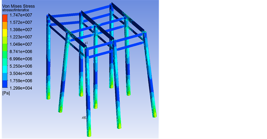
Figure 5. The stress distribution of construction platform.

Figure 6. The displacement distribution of construction platform.
・ The results of platform structure analysis show that the overall performance of this platform is quite good, but the stress concentrate on the connected nodes of steel pipe pile and laterals. So the design and construction of nodes should be strengthened to ensure the safety in the project.
Cite this paper
Yan, W.Y. and Lv, F.W. (2016) Numerical Simulation of Fluid Structure Interaction between Flow and Steel Pipe Pile Platform in Deep Water. World Journal of Engineering and Techno- logy, 4, 85-92. http://dx.doi.org/10.4236/wjet.2016.43C011
References
- 1. Liu, Y.J., Song, J.Y. and Zhu, L.H. (2013) Influence on Pile Frequency Characteristic by Fluid-Structure Interaction Effect. Harbor Engi-neering, 50, 22-24.
- 2. Rei, F. (2011) Dynamic Response Research of Submarine Flexible Structures with Fluid-Solid Interaction. Wuhan University of Technology, Wuhan.
- 3. Li, C. (2012) Fluid Structure Interaction Analysis of the Full Hydraulic Floating Wave Power Ge-nerator. Master’s Degree Thesis, Shandong University, Jinan.
- 4. Zuo, S.R. (2013) Study on Wave Effect of Bridge Pier of Crossing Bridge in Deep Water of Sea. Wuhan University of Technology, Wuhan.
- 5. Zhu, Y.R. (1998) Ocean Engineering Wave Mechanics. 1st Edition. Tianjin University Press, Tianjin.
- 6. Liu, Z.X., Song, B.J. and Valley, C.G. (1996) Numerical Study of High Order Anisotropic k -ε Models and Its Coefficients. Journal of Engineering Thermal Physics, 17, 31-34.