Paper Menu >>
Journal Menu >>
 Materials Sciences and Applicatio n, 2011, 2, 1143-1160 doi:10.4236/msa.2011.28155 Published Online August 2011 (http://www.SciRP.org/journal/msa) Copyright © 2011 SciRes. MSA 1143 Foundry Coating Technology: A Review U. C. Nwaogu*, N. S. Tiedje Technical University of Denmark, Department of Mechanical Engineering, Institute of Production and Process Technology, Kgs. Lyngby, Denmark. Email: *ugon@mek.dtu.dk Received April 27th, 2011; revised May 16th, 2011; accepted May 31st, 2011. ABSTRACT The importance of foundry coating in improving the surface quality of castings cannot be over emphasized. The appli- cation of mould and core washes creates a high thermal integrity barrier between the metal and the mould resulting in the reduction of the thermal shock experienced by the sand system. These thermal shock leads to series of surface de- fects such as veining/finning, metal penetration, burn-on/in, scab, rat tail, erosion etc. The use of coatings reduces the tendency of occurrence of these defects. However, the understanding of the coating, its components, characteristics and mechanism of action is important. In this review, a detailed description of these topics and examples are provided where necessary. A potential area of research in foundry coating development, using sol-gel process is suggested. The application of sol-gel technology in the development of foundry coatings is a novel approach. Keywords: Coating, Refractory Materials, Application Methods, Characterization, Sol-Gel Technology 1. Introduction Research in coatings for various applications such as aesthetics, corrosion protection, wear resistance, thermal barrier, self-cleaning, antifouling etc. have been very wide spread but not much is going on in the area of foundry coatings in recent times. The use of foundry coatings for moulds and cores during casting is very necessary as a means of achieving high quality surface finish of castings more especially in complex internal channels created by use of cores. This is despite the con- siderable advances that have taken place over the recent years in binder and sand technology giving the foundries greater opportunity to choose and control these basic foundry raw materials. Since casting surface finish de- pends largely on sand particle grading, it might be sup- posed that a proper selection of a particular grade of sand would be the only requirement to achieve the desired casting surface quality. However, there are other factors to be considered, such as the ability to vent off the gases produced during casting, economic use of a binder, non availability of sand with required grading, etc., these make the use of coatings the more practicable approach [1]. In filling a mould with liquid metal its surface is sub- jected to thermal, mechanical and physicochemical ac- tions. The oxidation products of the metal, reacting with the mould material, form low-melting materials such as silicates, which lubricate the grains of the quartz sand well. This promotes penetration of the metal into the in- ter-granular spaces and the formation of mechanical pick-up which is difficult to remove from the casting surface. Considering that the sand moulds and cores are highly porous, the production of castings in these materi- als without pick-up and other surface defects is possible only with protection of the surfaces of moulds and cores with refractory coatings. The fundamental requirements for the refractory coatings are minimum porosity, high refractoriness and reduction of the physicochemical reac- tion at the metal-coating interface (lubrication, solution, penetration) [2]. These refractory coatings are used to make better castings and to reduce costs. Castings sur- face quality is improved because the coating produces smoother metal surfaces, either by filling the spaces be- tween the sand grains or by providing, to the metal, a surface smoother than the mould surface itself. Further improvement from the coatings is due to the cleaner and better peel of sand at shakeout and elimination of certain defects such as metal penetration, veining, erosion, sand burn-in etc [3,4]. Controlling casting quality and increasing productivity are top priorities for foundries to become more competi- tive in a global casting market and coatings can help to provide the required remedy. Addressing the issue of mould/core moisture can lead to improvements in pro- ductivity and help keep foundries competitive. Identify- ing problems like poor mould/core density and moisture in the both core and mould is challenging, but advance-  Foundry Coating Technology: A Review 1144 ment in coating technology enhances the engineering of refractory coatings as a quality-control tool to help iden- tify these issues. The presence of moisture can lead to a scrapped casting, but coatings that indicate when drying is complete can address this issue. Coating technologies that change colour offer visual confirmation that the coating is dry. This confirmation may also indicate poor sand compaction in a core or mould, as these areas will absorb more moisture from the coating and take longer time to dry. Therefore, a visually obvious colour change based on moisture content permits these new refractory coatings to act not only as a barrier between the metal and the mould or core but also as a quality diagnostic [5]. The objective of this paper is to collate as much as possible the significant works and results on foundry coatings in the past and to give insight to a novel tech- nology for the production of foundry coatings with greater potential towards improving the surface quality of castings from readily available raw materials at a cheaper cost. This paper provides a detailed understanding of the constitution of foundry coatings while providing alterna- tives to the foundry coating components depending on the metal to be cast and their properties and compatibility with sand properties such as grain size and grain size distribution and binder properties. 2. Groups of Foundry Coatings Foundry coatings may be divided into two groups, those applied dry and those applied wet. 2.1. Coatings for Dry Application For dry application, the most widely used is Plumbago. Other dry coatings used to a lesser extent include mica, white talc and wheat flour. These materials are either shaken or blown onto mould or core surfaces from open-mesh cloth bags. Plumbago is a finely ground blend of graphite containing 80% to 90% of particles that will pass through a 200-mesh (75 micron). The graphite may be amorphous (no definite crystal structure) or crystalline (having definite particle shape or flaky). Graphite will not melt at the highest foundry temperatures but its car- bon is driven off by oxidation at these temperatures de- pending on the air (containing oxygen) available at the metal-mould interface. Amorphous graphite oxidizes easier than does crystalline graphite. Plumbago is applied dry only on green sand moulds [3]. 2.2. Coatings for Wet Application Mould and core coatings for wet application are of two types, carbon-base and carbon-free coatings. Both types are sold in either powder or paste form. The adherence of the coating on the mould or core surface depends on the moisture in the sand. Carbon-based coatings may contain several types of graphite, coke, anthracite or any of the numerous combinations that can be made from these materials. Carbon-free coatings may contain silica, mica, zircon flour, magnesite, olivine, clays, talc or a combina- tion of these materials. Many coatings formulations con- tain both carbonaceous and non-carbonaceous raw mate- rials to take the advantage of the synergistic characteris- tics of both types [3]. Foundry coatings for wet applica- tion are also classified into two, based on their carrier systems. Those employing an aqueous carrier and those in which organic solvent carriers are used. The former must be dried after application while the later are self-drying or can be ignited and dried by their own combustion. Both classes of coating make use of the re- fractory materials [6]. 3. Components of a Coating (Coating Materials) A refractory coating on the mould or core should have the following characteristics: Sufficient refractory properties to cope with the metal being poured Good adhesion to the substrate to prevent spalling Be permeable to minimize air entrapment Be fast in drying No tendency to blistering, cracking or scaling on dry- ing Good suspension and remixing properties Minimize core strength degradation Provide adequate protection against metal penetration Good stability in storage Good covering power Good application properties by the method chosen Leveling well and minimizing runs and tear drops For a coating to achieve these characteristics, the coating will consists of Refractory filler Liquid carrier Suspension agents (Rheology control system) Binder agents Additives as shown in Figure 1 3.1. Refractory Filler (Filler Materials) Refractory materials are substances or minerals that have high melting points and are difficult to fuse except at very high temperatures. They are processed at high tem- perature and/or intended for high temperature applica- tions [7,8]. Refractoriness has been defined by Commit- tee C-8 of the American Society for Testing and Materi- als (ASTM) as “...the capability of maintaining the de- sired degree of chemical and physical identity at high temperatures and in the environment and conditions of use.” The melting temperature of refractory materials is Copyright © 2011 SciRes. MSA 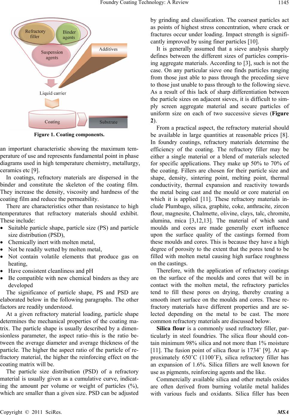 Foundry Coating Technology: A Review Copyright © 2011 SciRes. MSA 1145 Figure 1. Coating components. an important characteristic showing the maximum tem- perature of use and represents fundamental point in phase diagrams used in high temperature chemistry, metallurgy, ceramics etc [9]. In coatings, refractory materials are dispersed in the binder and constitute the skeleton of the coating film. They increase the density, viscosity and hardness of the coating film and reduce the permeability. There are characteristics other than resistance to high temperatures that refractory materials should exhibit. These include: Suitable particle shape, particle size (PS) and particle size distribution (PSD), Chemically inert with molten metal, Not be readily wetted by molten metal, Not contain volatile elements that produce gas on heating, Have consistent cleanliness and pH Be compatible with new chemical binders as they are developed The significance of particle shape, PS and PSD are elaborated below in the following paragraphs. The other factors are readily understood. At a given refractory material loading, particle shape determines the mechanical properties of the coating ma- trix. The particle shape is usually described by a dimen- sionless parameter, the aspect ratio–this is the ratio be- tween the average diameter and average thickness of the particle. The higher the aspect ratio of the particle of re- fractory material, the higher the reinforcing effect on the coating matrix will be. The particle size distribution (PSD) of a refractory material is usually given as a cumulative curve, indicat- ing the amount per volume or weight of particles (%), which are smaller than a given size. PSD can be adjusted by grinding and classification. The coarsest particles act as points of highest stress concentration, where crack or fractures occur under loading. Impact strength is signifi- cantly improved by using finer particles [10]. It is generally assumed that a sieve analysis sharply defines between the different sizes of particles compris- ing aggregate materials. According to [3], such is not the case. On any particular sieve one finds particles ranging from those just able to pass through the preceding sieve to those just unable to pass through to the following sieve. As a result of this lack of sharp differentiation between the particle sizes on adjacent sieves, it is difficult to sim- ply screen aggregate material and secure particles of uniform size on each of two successive sieves (Figure 2). From a practical aspect, the refractory material should be available in large quantities at reasonable prices [8]. In foundry coatings, refractory materials determine the efficiency of the coating. The refractory filler may be either a single material or a blend of materials selected for specific applications. They make up 50% to 70% of the coating. Fillers are chosen for their particle size and shape, density, sintering point, melting point, thermal conductivity, thermal expansion and reactivity towards the metal being cast and the mould or core material on which it is applied [11]. These refractory materials in- clude Plumbago, silica, graphite, coke, anthracite, zircon flour, magnesite, Chalmette, olivine, clays, talc, chromite, alumina, mica [3,12,13]. The material of which sand moulds and cores are made generally exert influence upon the surface quality of the castings formed from these moulds and cores. This is because they have a high degree of porosity to the extent that the pores tend to be filled with molten metal causing high surface roughness on the castings. Therefore, with the application of refractory coatings on the surface of the moulds and cores that will be in contact with the molten metal, the refractory particles tend to fill these pores on drying, thereby creating a smooth inert surface on the moulds and cores. These re- fractory materials have different properties and are se- lected depending on the metal to be cast. The more common refractory materials are discussed below. Silica flour is a commonly used refractory filler, par- ticularly in steel foundries. The silica flour should con- tain minimum 98% silica and not more than 1% moisture [11]. The fusion point of silica flour is 1734˚ [9]. At ap- proximately 650˚C (1100˚F), silica refractory filler has an expansion of 1.6%. Silica fillers are well known for use as pigments, reinforcing agents and the like. Commercially available silica and other metals oxides are often derived from burning volatile metal halides with various fuels and oxidants. Silica filler has been 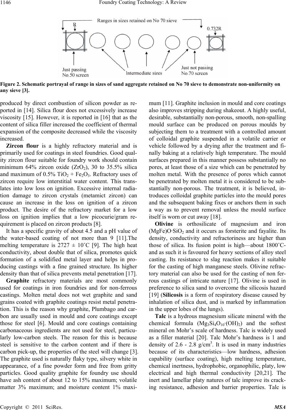 Foundry Coating Technology: A Review 1146 Figure 2. Schematic portrayal of range in sizes of sand aggregate retained on No 70 sieve to demonstrate non-uniformity on any sieve [3]. produced by direct combustion of silicon powder as re- ported in [14]. Silica flour does not excessively increase viscosity [15]. However, it is reported in [16] that as the content of silica filler increased the coefficient of thermal expansion of the composite decreased while the viscosity increased. Zircon flour is a highly refractory material and is primarily used for coatings in steel foundries. Good qual- ity zircon flour suitable for foundry work should contain minimum 64% zircon oxide (ZrO2), 30 to 35.5% silica and maximum of 0.5% TiO2 + Fe2O3. Refractory uses of zircon require low interstitial water content. This trans- lates into low loss on ignition. Excessive internal radia- tion damage to zircon crystals (metamict zircon) can cause an increase in the loss on ignition of a zircon product. The desire of the refractory market for a low loss on ignition implies that a low picocurie/gram re- quirement is placed on zircon products [8]. It has a specific gravity of about 4.5 and a pH value of the water-based coating of not more than 9 [11].The melting temperature is 2727 ± 10˚C [9]. The high heat conductivity, about double that of silica, promotes quick formation of a solidified metal layer and helps in pro- ducing castings with a fine grained structure. Its higher density than that of silica prevents metal penetration [17]. Graphite refractory materials are most commonly used for coatings in iron foundries and for non-ferrous castings. Molten metal does not wet graphite and sand grains coated with graphite coatings resist metal penetra- tion. This is the reason why graphite, Plumbago and car- bon are usually used in mould and core coatings except those for steel [6]. Mould and core coatings containing carbonaceous ingredients are not used for steel, particu- larly low-carbon steels. The reason for this is because steel is sensitive to the carbon content and if there is carbon pick-up, the properties of the steel will change [3]. The graphite used is naturally flaky type, silvery white in appearance, of a fine powder form and free from gritty particles. Good quality graphite for foundry use should have ash content of about 12 to 15% maximum; volatile matter 3% maximum; and moisture content 1% maxi- mum [11]. Graphite inclusion in mould and core coatings also improves stripping during shakeout. A highly useful, desirable, substantially non-porous, smooth, non-spalling mould surface can be produced on porous moulds by subjecting them to a treatment with a controlled amount of colloidal graphite suspended in a volatile carrier or vehicle followed by a drying after the treatment and fi- nally baking at a relatively high temperature. The mould surfaces prepared in this manner possess substantially no pores, at least those of a size which can be penetrated by molten metal. With the presence of pores which cannot be penetrated by molten metal it is considered to be sub- stantially non-porous. The treatment, it is believed, in- troduces colloidal graphite particles into the mould pores and the subsequent baking fixes or anchors them in such a way as to prevent removal unless the mould surface itself is worn or cut away [18]. Olivine is orthosilicate of magnesium and iron (MgFe)O·SiO2 and it occurs as forsterite and fayalite. Its density, conductivity and refractoriness are higher than those of silica. Its fusion point is high—about 1800˚C- and as such it is favoured for heavy sections of alloy steel casting. Its resistance to slag reaction makes it suitable for the casting of high manganese steels. Olivine refrac- tory material can also be used for the casting of non fer- rous castings of intricate nature [17]. Olivine is used in preference to silica sand to overcome the silicosis hazard [19] (Silicosis is a form of respiratory disease caused by inhalation of silica dust, and is marked by inflammation in the upper lobes of the lungs). Talc is a hydrous magnesium silicate mineral with the chemical formula (Mg3Si4O10·(OH)2) and the softest mineral on Mohr’s scale of hardness. Talc is widely used as a filler material [20]. Talc Mohr’s hardness is 1 and density of 2.6 - 2.8 g/cm3. It is used in many industries because of its characteristics—low hardness, adhesion capability (surface coating), high melting temperature, chemical inertness, hydrophobic, organophilic, platy, low electrical and high thermal conductivity [20,21]. The inert and lamellar platy natures of talc improve its crack- ing resistance, adhesion and barrier properties. Talc is Copyright © 2011 SciRes. MSA 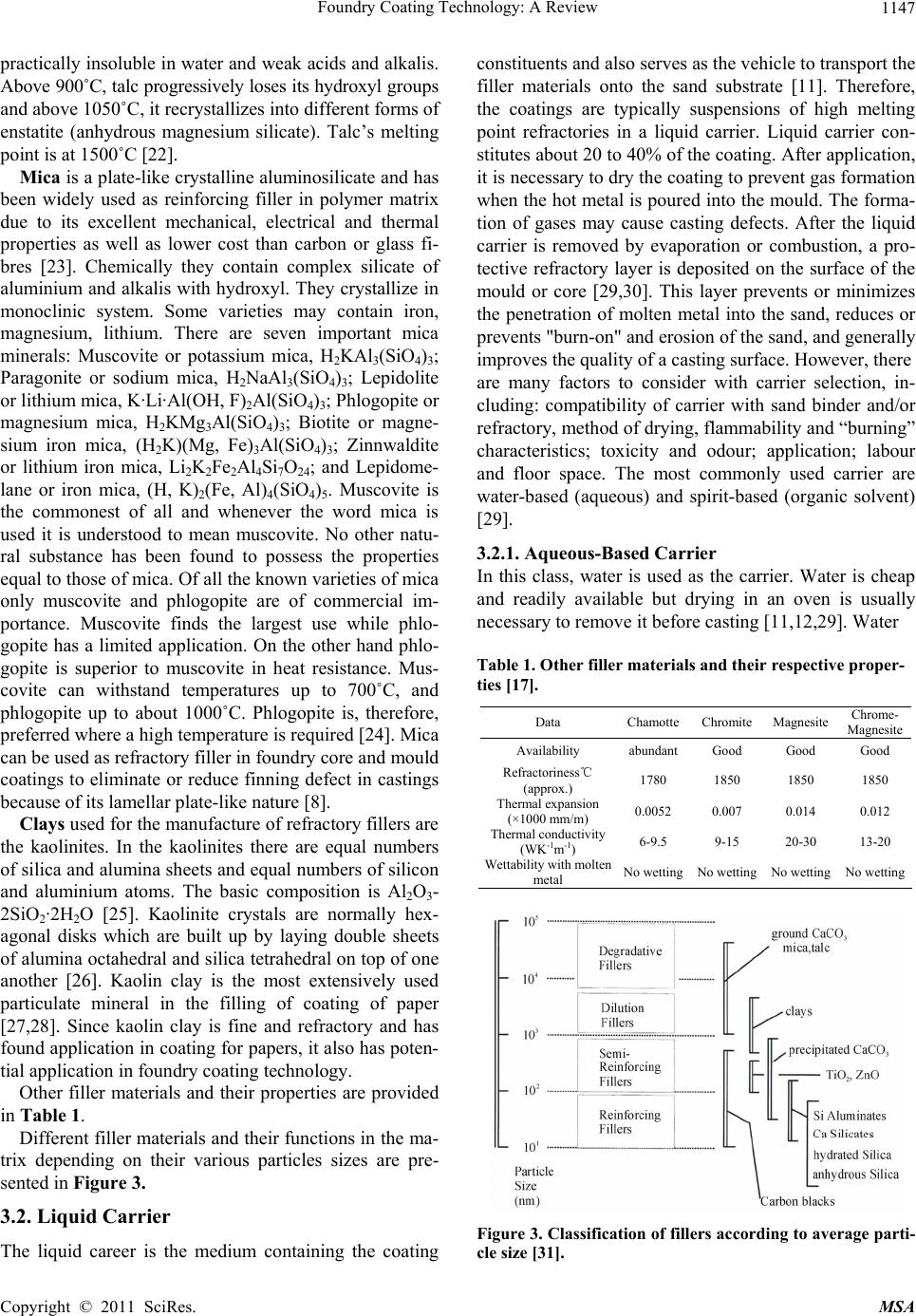 Foundry Coating Technology: A Review1147 practically insoluble in water and weak acids and alkalis. Above 900˚C, talc progressively loses its hydroxyl groups and above 1050˚C, it recrystallizes into different forms of enstatite (anhydrous magnesium silicate). Talc’s melting point is at 1500˚C [22]. Mica is a plate-like crystalline aluminosilicate and has been widely used as reinforcing filler in polymer matrix due to its excellent mechanical, electrical and thermal properties as well as lower cost than carbon or glass fi- bres [23]. Chemically they contain complex silicate of aluminium and alkalis with hydroxyl. They crystallize in monoclinic system. Some varieties may contain iron, magnesium, lithium. There are seven important mica minerals: Muscovite or potassium mica, H2KAl3(SiO4)3; Paragonite or sodium mica, H2NaAl3(SiO4)3; Lepidolite or lithium mica, K·Li·Al(OH, F)2Al(SiO4)3; Phlogopite or magnesium mica, H2KMg3Al(SiO4)3; Biotite or magne- sium iron mica, (H2K)(Mg, Fe)3Al(SiO4)3; Zinnwaldite or lithium iron mica, Li2K2Fe2Al4Si7O24; and Lepidome- lane or iron mica, (H, K)2(Fe, Al)4(SiO4)5. Muscovite is the commonest of all and whenever the word mica is used it is understood to mean muscovite. No other natu- ral substance has been found to possess the properties equal to those of mica. Of all the known varieties of mica only muscovite and phlogopite are of commercial im- portance. Muscovite finds the largest use while phlo- gopite has a limited application. On the other hand phlo- gopite is superior to muscovite in heat resistance. Mus- covite can withstand temperatures up to 700˚C, and phlogopite up to about 1000˚C. Phlogopite is, therefore, preferred where a high temperature is required [24]. Mica can be used as refractory filler in foundry core and mould coatings to eliminate or reduce finning defect in castings because of its lamellar plate-like nature [8]. Clays used for the manufacture of refractory fillers are the kaolinites. In the kaolinites there are equal numbers of silica and alumina sheets and equal numbers of silicon and aluminium atoms. The basic composition is Al2O3- 2SiO2·2H2O [25]. Kaolinite crystals are normally hex- agonal disks which are built up by laying double sheets of alumina octahedral and silica tetrahedral on top of one another [26]. Kaolin clay is the most extensively used particulate mineral in the filling of coating of paper [27,28]. Since kaolin clay is fine and refractory and has found application in coating for papers, it also has poten- tial application in foundry coating technology. Other filler materials and their properties are provided in Table 1. Different filler materials and their functions in the ma- trix depending on their various particles sizes are pre- sented in Figure 3. 3.2. Liquid Carrier The liquid career is the medium containing the coating constituents and also serves as the vehicle to transport the filler materials onto the sand substrate [11]. Therefore, the coatings are typically suspensions of high melting point refractories in a liquid carrier. Liquid carrier con- stitutes about 20 to 40% of the coating. After application, it is necessary to dry the coating to prevent gas formation when the hot metal is poured into the mould. The forma- tion of gases may cause casting defects. After the liquid carrier is removed by evaporation or combustion, a pro- tective refractory layer is deposited on the surface of the mould or core [29,30]. This layer prevents or minimizes the penetration of molten metal into the sand, reduces or prevents "burn-on" and erosion of the sand, and generally improves the quality of a casting surface. However, there are many factors to consider with carrier selection, in- cluding: compatibility of carrier with sand binder and/or refractory, method of drying, flammability and “burning” characteristics; toxicity and odour; application; labour and floor space. The most commonly used carrier are water-based (aqueous) and spirit-based (organic solvent) [29]. 3.2.1. Aqueous-Based Carrier In this class, water is used as the carrier. Water is cheap and readily available but drying in an oven is usually necessary to remove it before casting [11,12,29]. Water Table 1. Other filler materials and their respective proper- ties [17]. Data ChamotteChromite MagnesiteChrome- Magnesite Availability abundantGood Good Good Refractoriness℃ (approx.) 1780 1850 1850 1850 Thermal expansion (×1000 mm/m) 0.0052 0.007 0.014 0.012 Thermal conductivity (WK-1m-1) 6-9.5 9-15 20-30 13-20 Wettability with molten metal No wettingNo wetting No wettingNo wetting Figure 3. Classification of fillers according to average parti- cle size [31]. Copyright © 2011 SciRes. MSA 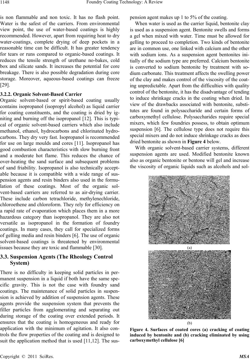 Foundry Coating Technology: A Review 1148 is non flammable and non toxic. It has no flash point. Water is the safest of the carriers. From environmental view point, the use of water-based coatings is highly recommended. However, apart from requiring heat to dry water-coatings, complete drying of deep pockets in a reasonable time can be difficult. It has greater tendency for tears or runs compared to organic-based coatings. It reduces the tensile strength of urethane no-bakes, cold box and silicate sands. It increases the potential for core breakage. There is also possible degradation during core storage. Moreover, aqueous-based coatings can freeze [29]. 3.2.2. Organic Solvent-Based Carrier Organic solvent-based or spirit-based coating usually contains isopropanol (isopropyl alcohol) as liquid carrier for coating constituents, and the coating is dried by ig- niting and burning off the isopropanol [12]. This is typi- cal of organic solvent-based carriers which also include methanol, ethanol, hydrocarbons and chlorinated hydro- carbons. They dry very fast. Isopropanol is recommended for use on large moulds and cores [11]. Isopropanol has good combustion characteristics with slow burning front and a moderate hot flame. This reduces the chance of over-heating the sand surface and subsequent problems of sand friability. Isopropanol is also technically accept- able because it is compatible with a wide range of sus- pension agents and resin binders also used in the formu- lation of these coatings. Most of the organic sol- vent-based carriers are referred to as air-drying carrier. These include carbon tetrachloride, methylenechloride, chloroethene and chloroform. They rely for efficiency on a rapid rate of evaporation which places them in a more hazardous category than isopropanol. They are also not versatile as isopropanol in the formation of foundry coatings. In many cases, they call for specialized forms of gelling media and resin binders [6]. The use of organic solvent-based coatings is threatened by environmental issues because they are toxic and flammable [30]. 3.3. Suspension Agents (The Rheology Control System) There is no difficulty in keeping solid particles in per- manent suspension in a liquid if both have the same spe- cific gravity. This is not the case with foundry sand coatings. The maintenance of solid particles in suspen- sion is achieved by addition of suspension agents. These agents provide the suspension system that prevents the filler particles from agglomerating and separating out during storage of the coating over extended periods. It ensures that the coating is homogeneous and ready for application with the minimum of agitation. It also con- trols the flow properties of the coating and is designed to suit the application method that is used [11,12]. The sus- pension agent makes up 1 to 5% of the coating. When water is used as the carrier liquid, bentonite clay is used as a suspension agent. Bentonite swells and forms a gel when mixed with water. Time must be allowed for gelling to proceed to completion. Two kinds of bentonite are in common use, one linked with calcium and the other with sodium ions. As a suspension agent bentonites ini- tially of the sodium type are preferred. Calcium bentonite is converted to sodium bentonite by treatment with so- dium carbonate. This treatment affects the swelling power of the clay and makes control of the viscosity of the coat- ing unpredictable. Apart from the difficulties with quality control of the bentonite, it has the disadvantage of tending to induce shrinkage cracks in the coating when dried. In view of the drawbacks associated with bentonite, substi- tutes are found in polysaccharide and certain forms of carboxymethyl cellulose. Polysaccharides require special mixers, which few foundries possess, to obtain optimum suspension [6]. The cellulose type does not require this special mixers and do not induce shrinkage cracks as does dried bentonite as shown in Figure 4 below. With organic solvent-based carrier systems, different suspension agents are used. Modified bentonite known also as organic bentonite or bentone will gel and increase the viscosity of organic liquids such as alcohols and sol- (a) (b) Figure 4. Surfaces of coated cores (a) cracking of coating induced by bentonite and (b) cracking eliminated by using carboxymethyl cellulose [6] Copyright © 2011 SciRes. MSA 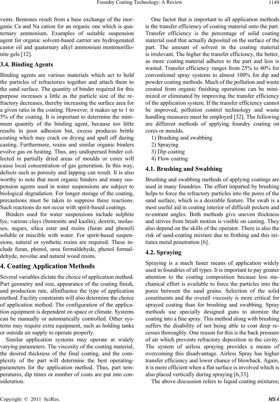 Foundry Coating Technology: A Review1149 vents. Bentones result from a base exchange of the inor- ganic Ca and Na cation for an organic one which is qua- ternary ammonium. Examples of suitable suspension agent for organic solvent-based carrier are hydrogenated castor oil and quaternary alkyl ammonium montmorillo- nite gels [12]. 3.4. Binding Agents Binding agents are various materials which act to hold the particles of refractories together and attach them to the sand surface. The quantity of binder required for this purpose increases a little as the particle size of the re- fractory decreases, thereby increasing the surface area for a given ratio in the coating. However, it makes up to 1 to 5% of the coating. It is important to determine the mini- mum quantity of the binding agent, because too little results in poor adhesion but, excess produces brittle coating which may crack on drying and spall off during casting. Furthermore, resins and similar organic binders evolve gas on heating. Thus, any undispersed binder col- lected in partially dried areas of moulds or cores will cause local concentration of gas generation. In this way, defects such as porosity and lapping can result. It is also worthy to note that most organic binders and many sus- pension agents used in water suspensions are subject to biological degradation. For longer storage of the coating, precautions must be taken to suppress these reactions. Such reactions do not occur with spirit-based coatings. Binders used for water suspensions include sulphite lye, various clays (bentonite and kaolin), dextrin, molas- ses, sugars, silica ester and resins (furan and phenol) soluble or miscible with water. For spirit-based suspen- sions, natural or synthetic resins are required. These in- clude furan, phenol, urea formaldehyde, phenol formal- dehyde, novolac and natural wood resins. 4. Coating Application Methods Several variables dictate the choice of application method. Part geometry and size, appearance of the coating finish, and production rate, allinfluence the type of application method. Facility constraints will also determine the choice of application method. The configuration of the applica- tion equipment is dependent on space or climate. Systems can be manually or automatically controlled. Other sys- tems may require extra equipment, such as holding tanks or outside air supply to operate properly. Similar application systems may operate at widely varying parameters. The viscosity of the coating material, the desired thickness of the final coating, and the com- plexity of the part will determine the best operating- parameters for the application method. Thus, part tem- peratures, dip times or number of coats are put into con- sideration. One factor that is important to all application methods is the transfer efficiency of coating material onto the part. Transfer efficiency is the percentage of solid coating material used that actually deposited on the surface of the part. The amount of solvent in the coating material is irrelevant. The higher the transfer efficiency, the better, as more coating material adheres to the part and less is wasted. Transfer efficiency ranges from 25% to 40% for conventional spray systems to almost 100% for dip and powder coating methods. Much of the pollution and waste created from organic finishing operations can be mini- mized or eliminated by improving the transfer efficiency of the application system. If the transfer efficiency cannot be improved, pollution control technology and waste handling measures must be employed [32]. The following are different methods of applying foundry coating on cores or moulds. 1) Brushing and swabbing 2) Spraying 3) Dip coating 4) Flow coating 4.1. Brushing and Swabbing Brushing and swabbing methods of applying coatings are used in many foundries. The effort imparted by brushing helps to force the refractory particles into the pores of the sand surface, which is a desirable feature. The swab is a most useful aid in coating interior of difficult pockets and re-entrant angles. Both methods give uneven thickness and strives from brush motion is visible on casting. They also depend on the skills of the operator. There is also the risk of sand-coating mixture due to frothing and this ini- tiates metal penetration [6]. 4.2. Spraying Spraying is a much faster means of application widely used in foundries of all types. It is important to pay greater attention to the coating composition because less me- chanical effort is available to force the particles into the pores between the sand grains. Selection of the solid constituents and the overall viscosity is more critical for sprayed coating than for brushing and swabbing. Spray methods use specially designed guns to atomize the coating into a fine spray. This method along with brushing suffers the disability of not being able to coat deep re- cesses thoroughly. One reason for this is the back pressure of air which prevents refractory deposition in the cavity. The system of airless spraying provides a means of overcoming this disadvantage. Airless Spray has higher transfer efficiency and lower chance of blowback. Again, it is more efficient when a flat surface is involved which is also placed vertically during spraying [6,33]. The above discussion refers to liquid coating mixtures; Copyright © 2011 SciRes. MSA 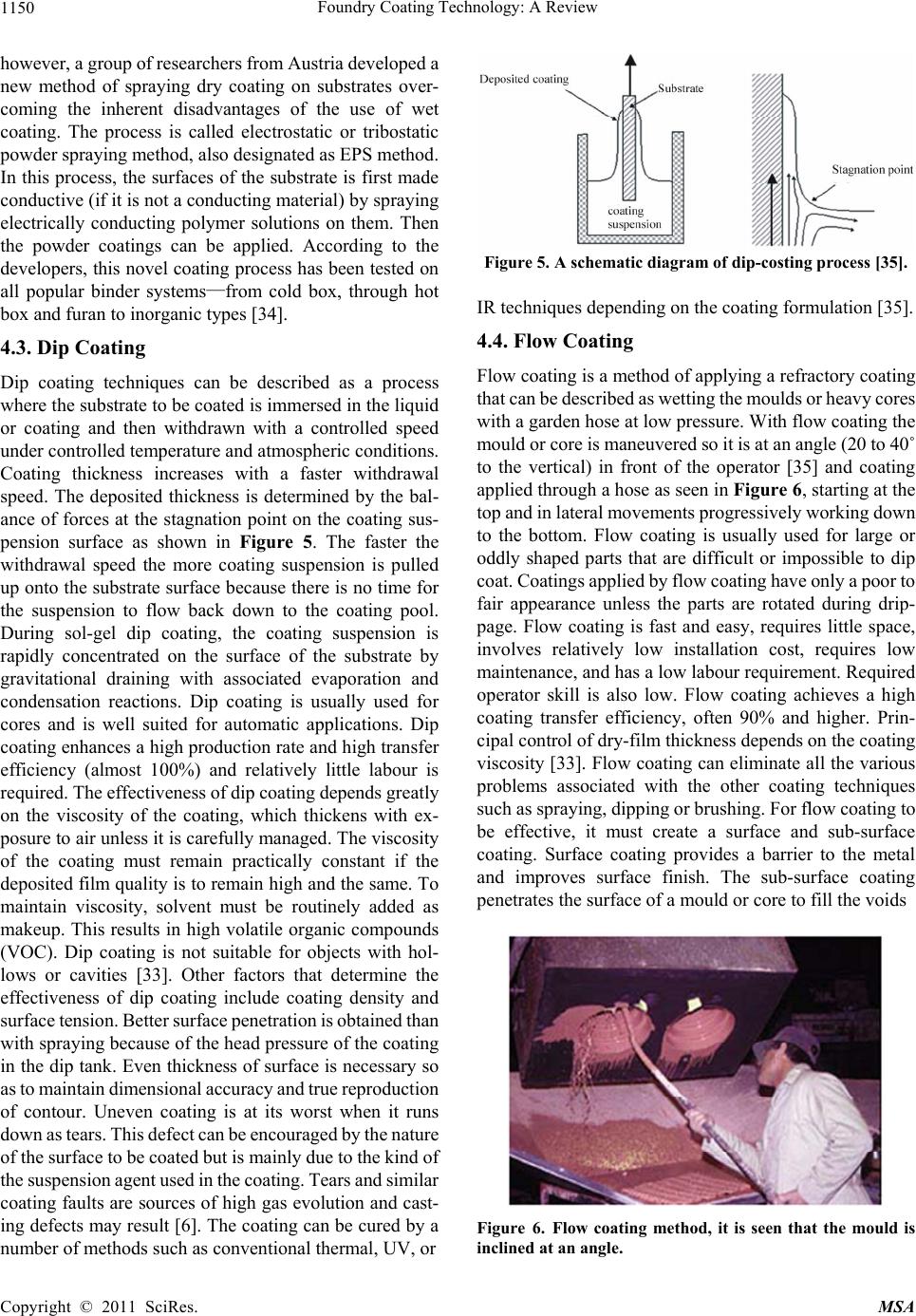 Foundry Coating Technology: A Review 1150 however, a group of researchers from Austria developed a new method of spraying dry coating on substrates over- coming the inherent disadvantages of the use of wet coating. The process is called electrostatic or tribostatic powder spraying method, also designated as EPS method. In this process, the surfaces of the substrate is first made conductive (if it is not a conducting material) by spraying electrically conducting polymer solutions on them. Then the powder coatings can be applied. According to the developers, this novel coating process has been tested on all popular binder systems—from cold box, through hot box and furan to inorganic types [34]. 4.3. Dip Coating Dip coating techniques can be described as a process where the substrate to be coated is immersed in the liquid or coating and then withdrawn with a controlled speed under controlled temperature and atmospheric conditions. Coating thickness increases with a faster withdrawal speed. The deposited thickness is determined by the bal- ance of forces at the stagnation point on the coating sus- pension surface as shown in Figure 5. The faster the withdrawal speed the more coating suspension is pulled up onto the substrate surface because there is no time for the suspension to flow back down to the coating pool. During sol-gel dip coating, the coating suspension is rapidly concentrated on the surface of the substrate by gravitational draining with associated evaporation and condensation reactions. Dip coating is usually used for cores and is well suited for automatic applications. Dip coating enhances a high production rate and high transfer efficiency (almost 100%) and relatively little labour is required. The effectiveness of dip coating depends greatly on the viscosity of the coating, which thickens with ex- posure to air unless it is carefully managed. The viscosity of the coating must remain practically constant if the deposited film quality is to remain high and the same. To maintain viscosity, solvent must be routinely added as makeup. This results in high volatile organic compounds (VOC). Dip coating is not suitable for objects with hol- lows or cavities [33]. Other factors that determine the effectiveness of dip coating include coating density and surface tension. Better surface penetration is obtained than with spraying because of the head pressure of the coating in the dip tank. Even thickness of surface is necessary so as to maintain dimensional accuracy and true reproduction of contour. Uneven coating is at its worst when it runs down as tears. This defect can be encouraged by the nature of the surface to be coated but is mainly due to the kind of the suspension agent used in the coating. Tears and similar coating faults are sources of high gas evolution and cast- ing defects may result [6]. The coating can be cured by a number of methods such as conventional thermal, UV, or Figure 5. A schematic diagram of dip-costing process [35]. IR techniques depending on the coating formulation [35]. 4.4. Flow Coating Flow coating is a method of applying a refractory coating that can be described as wetting the moulds or heavy cores with a garden hose at low pressure. With flow coating the mould or core is maneuvered so it is at an angle (20 to 40˚ to the vertical) in front of the operator [35] and coating applied through a hose as seen in Figure 6, starting at the top and in lateral movements progressively working down to the bottom. Flow coating is usually used for large or oddly shaped parts that are difficult or impossible to dip coat. Coatings applied by flow coating have only a poor to fair appearance unless the parts are rotated during drip- page. Flow coating is fast and easy, requires little space, involves relatively low installation cost, requires low maintenance, and has a low labour requirement. Required operator skill is also low. Flow coating achieves a high coating transfer efficiency, often 90% and higher. Prin- cipal control of dry-film thickness depends on the coating viscosity [33]. Flow coating can eliminate all the various problems associated with the other coating techniques such as spraying, dipping or brushing. For flow coating to be effective, it must create a surface and sub-surface coating. Surface coating provides a barrier to the metal and improves surface finish. The sub-surface coating penetrates the surface of a mould or core to fill the voids Figure 6. Flow coating method, it is seen that the mould is inclined at an angle. Copyright © 2011 SciRes. MSA 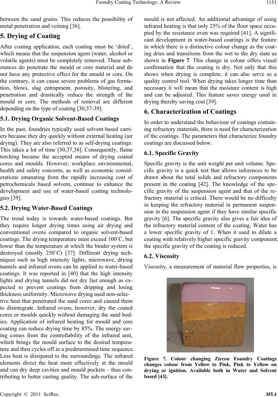 Foundry Coating Technology: A Review1151 between the sand grains. This reduces the possibility of metal penetration and veining [36]. 5. Drying of Coating After coating application, each coating must be ‘dried’, which means that the suspension agent (water, alcohol or volatile agents) must be completely removed. These sub- stances do penetrate the mould or core material and do not have any protective effect for the mould or core. On the contrary, it can cause severe problems of gas forma- tion, blows, slag entrapment, porosity, blistering, and penetration and drastically reduce the strength of the mould or core. The methods of removal are different depending on the type of coating [30,37-39]. 5.1. Drying Organic Solvent-Based Coatings In the past, foundries typically used solvent-based carri- ers because they dry quickly without external heating (air drying). They are also referred to as self-drying coatings. This takes a lot of time [30,37,38]. Consequently, flame torching became the accepted means of drying coated cores and moulds. However, workplace environmental, health and safety concerns, as well as economic consid- erations emanating from the rapidly increasing cost of petrochemicals based solvent, continue to enhance the development and use of water-based coating technolo- gies [39]. 5.2. Drying Water-Based Coatings The trend today is towards water-based coatings. But they require longer drying times using air drying and conventional ovens compared to organic solvent-based coatings. The drying temperature must exceed 100˚C, but lower than the temperature at which the binder system is destroyed (mostly 250˚C) [37]. Different drying tech- niques such as high intensity lights, microwave, drying tunnels and infrared ovens can be applied to water-based coatings. It was reported in [40] that the high intensity lights and drying tunnels did not dry fast enough as ex- pected to prevent coatings from dripping and losing thickness uniformity. Microwave drying used non-selec- tive heat that penetrated the sand cores and caused them to disintegrate. Infrared ovens, however, dry the coated cores or moulds quickly without damaging the sand bod- ies. Application of infrared heating for mould and core coating can reduce drying time by 85%. The energy sav- ing comes from the controllability of the infrared unit, which brings the mould surface to the desired tempera- ture and then cycles off in a predetermined time sequence. Less heat is dissipated to the surroundings. The infrared elements direct the heat more effectively at the mould and can dry deep cavities and mould pockets – thus con- tributing to better casting quality. The sub-surface of the mould is not affected. An additional advantage of using infrared heating is that only 25% of the floor space occu- pied by the resistance oven was required [41]. A signifi- cant development in water-based coatings is the feature in which there is a distinctive colour change as the coat- ing dries and transitions from the wet to the dry state as shown in Figure 7. This change in colour offers visual confirmation that the coating is dry. Not only that this shows when drying is complete, it can also serve as a quality control tool. When drying takes longer time than necessary it will mean that the moisture content is high and can be adjusted. This feature saves energy used in drying thereby saving cost [39]. 6. Characterization of Coatings In order to understand the behaviour of coatings contain- ing refractory materials, there is need for characterization of the coatings. The parameters that characterize foundry coatings are discussed below. 6.1. Specific Gravity Specific gravity is the unit weight per unit volume. Spe- cific gravity is a quick test that allows inferences to be drawn about the total solids and refractory components present in the coating [42]. The knowledge of the spe- cific gravity of the suspension agent and that of the re- fractory material is critical. There would be no difficulty in keeping the refractory material in permanent suspen- sion in the suspension agent if they have similar specific gravity [6]. The specific gravity also gives a fair idea of the refractory material content of the coating. Water has a lower specific gravity of 1. When it used to dilute a coating with relatively higher specific gravity component; the specific gravity of the coating is reduced. 6.2. Viscosity Viscosity, a measurement of material flow properties, is Figure 7. Colour changing Zircon Foundry Coatings changes colour from Yellow to Pink, Pink to Yellow on drying or ignition. Available both in Water and Solvent based [43]. Copyright © 2011 SciRes. MSA 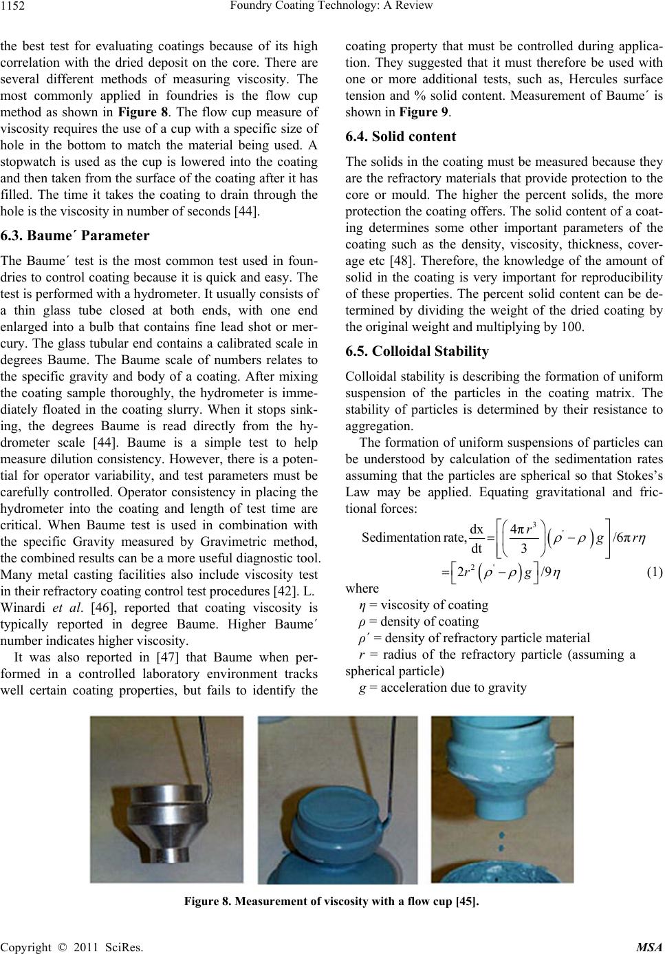 Foundry Coating Technology: A Review Copyright © 2011 SciRes. MSA 1152 coating property that must be controlled during applica- tion. They suggested that it must therefore be used with one or more additional tests, such as, Hercules surface tension and % solid content. Measurement of Baume´ is shown in Figure 9. the best test for evaluating coatings because of its high correlation with the dried deposit on the core. There are several different methods of measuring viscosity. The most commonly applied in foundries is the flow cup method as shown in Figure 8. The flow cup measure of viscosity requires the use of a cup with a specific size of hole in the bottom to match the material being used. A stopwatch is used as the cup is lowered into the coating and then taken from the surface of the coating after it has filled. The time it takes the coating to drain through the hole is the viscosity in number of seconds [44]. 6.4. Solid content The solids in the coating must be measured because they are the refractory materials that provide protection to the core or mould. The higher the percent solids, the more protection the coating offers. The solid content of a coat- ing determines some other important parameters of the coating such as the density, viscosity, thickness, cover- age etc [48]. Therefore, the knowledge of the amount of solid in the coating is very important for reproducibility of these properties. The percent solid content can be de- termined by dividing the weight of the dried coating by the original weight and multiplying by 100. 6.3. Baume´ Parameter The Baume´ test is the most common test used in foun- dries to control coating because it is quick and easy. The test is performed with a hydrometer. It usually consists of a thin glass tube closed at both ends, with one end enlarged into a bulb that contains fine lead shot or mer- cury. The glass tubular end contains a calibrated scale in degrees Baume. The Baume scale of numbers relates to the specific gravity and body of a coating. After mixing the coating sample thoroughly, the hydrometer is imme- diately floated in the coating slurry. When it stops sink- ing, the degrees Baume is read directly from the hy- drometer scale [44]. Baume is a simple test to help measure dilution consistency. However, there is a poten- tial for operator variability, and test parameters must be carefully controlled. Operator consistency in placing the hydrometer into the coating and length of test time are critical. When Baume test is used in combination with the specific Gravity measured by Gravimetric method, the combined results can be a more useful diagnostic tool. Many metal casting facilities also include viscosity test in their refractory coating control test procedures [42]. L. 6.5. Colloidal Stability Colloidal stability is describing the formation of uniform suspension of the particles in the coating matrix. The stability of particles is determined by their resistance to aggregation. The formation of uniform suspensions of particles can be understood by calculation of the sedimentation rates assuming that the particles are spherical so that Stokes’s Law may be applied. Equating gravitational and fric- tional forces: 3 ' dx 4π Sedimentation rate,/6π dt 3 r g r 2' 2rg/9 (1) where η = viscosity of coating Winardi et al. [46], reported that coating viscosity is typically reported in degree Baume. Higher Baume´ number indicates higher viscosity. ρ = density of coating ρ´ = density of refractory particle material r = radius of the refractory particle (assuming a spherical particle) It was also reported in [47] that Baume when per- formed in a controlled laboratory environment tracks well certain coating properties, but fails to identify the g = acceleration due to gravity Figure 8. Measurement of viscosity with a flow cup [45]. 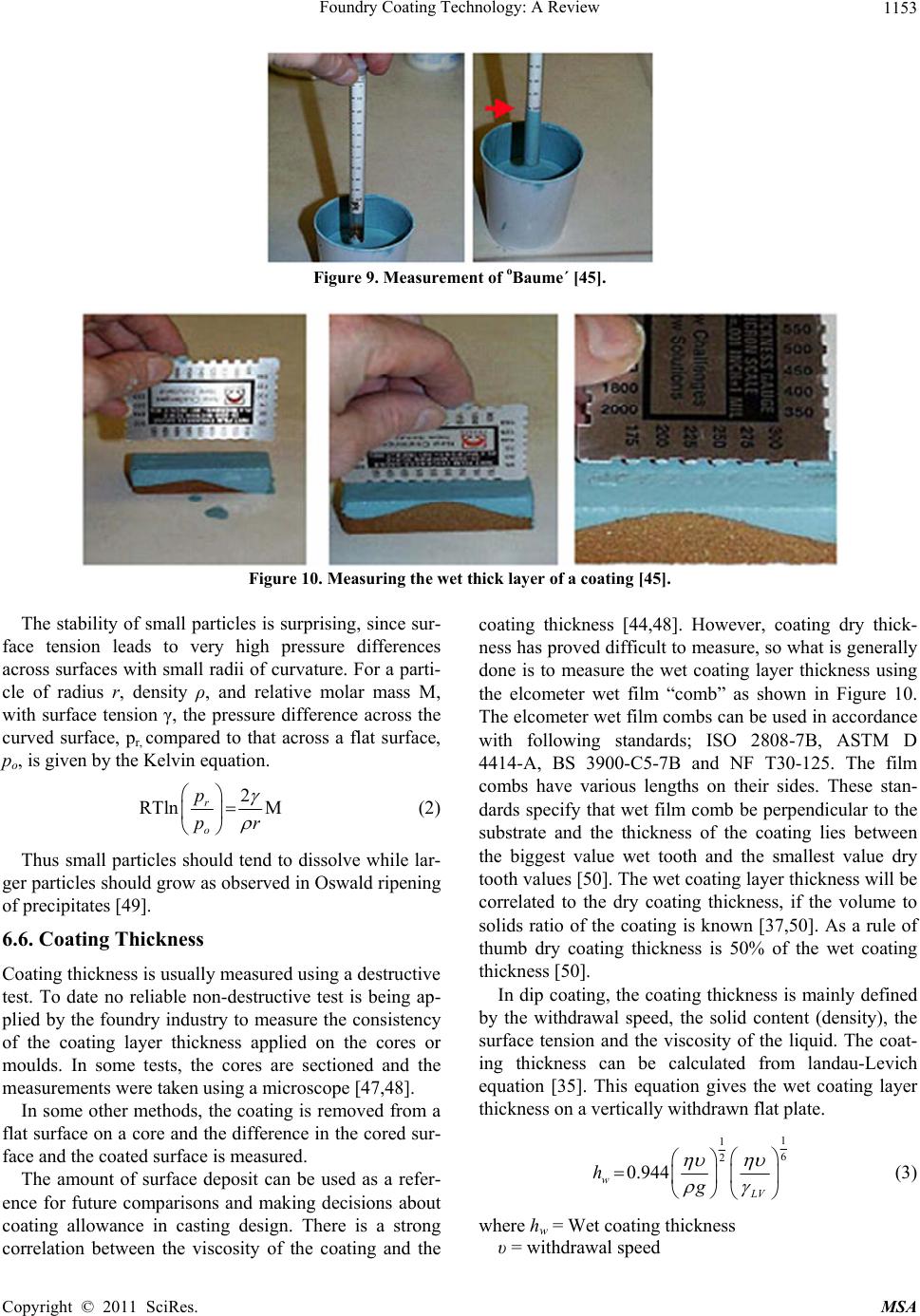 Foundry Coating Technology: A Review1153 Figure 9. Measurement of oBaume´ [45]. Figure 10. Measuring the wet thick layer of a coating [45]. The stability of small particles is surprising, since sur- face tension leads to very high pressure differences across surfaces with small radii of curvature. For a parti- cle of radius r, density ρ, and relative molar mass M, with surface tension γ, the pressure difference across the curved surface, pr, compared to that across a flat surface, po, is given by the Kelvin equation. 2 RTln M r o p pr (2) Thus small particles should tend to dissolve while lar- ger particles should grow as observed in Oswald ripening of precipitates [49]. 6.6. Coating Thickness Coating thickness is usually measured using a destructive test. To date no reliable non-destructive test is being ap- plied by the foundry industry to measure the consistency of the coating layer thickness applied on the cores or moulds. In some tests, the cores are sectioned and the measurements were taken using a microscope [47,48]. In some other methods, the coating is removed from a flat surface on a core and the difference in the cored sur- face and the coated surface is measured. The amount of surface deposit can be used as a refer- ence for future comparisons and making decisions about coating allowance in casting design. There is a strong correlation between the viscosity of the coating and the coating thickness [44,48]. However, coating dry thick- ness has proved difficult to measure, so what is generally done is to measure the wet coating layer thickness using the elcometer wet film “comb” as shown in Figure 10. The elcometer wet film combs can be used in accordance with following standards; ISO 2808-7B, ASTM D 4414-A, BS 3900-C5-7B and NF T30-125. The film combs have various lengths on their sides. These stan- dards specify that wet film comb be perpendicular to the substrate and the thickness of the coating lies between the biggest value wet tooth and the smallest value dry tooth values [50]. The wet coating layer thickness will be correlated to the dry coating thickness, if the volume to solids ratio of the coating is known [37,50]. As a rule of thumb dry coating thickness is 50% of the wet coating thickness [50]. In dip coating, the coating thickness is mainly defined by the withdrawal speed, the solid content (density), the surface tension and the viscosity of the liquid. The coat- ing thickness can be calculated from landau-Levich equation [35]. This equation gives the wet coating layer thickness on a vertically withdrawn flat plate. 1 1 6 2 0.944 w LV hg (3) where hw = Wet coating thickness υ = withdrawal speed Copyright © 2011 SciRes. MSA 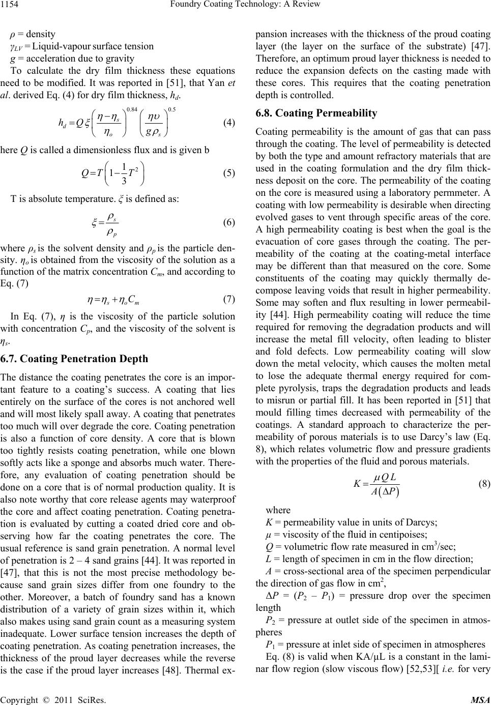 Foundry Coating Technology: A Review 1154 ρ = density γLV = Liquid-vapour surface tension g = acceleration due to gravity To calculate the dry film thickness these equations need to be modified. It was reported in [51], that Yan et al. derived Eq. (4) for dry film thickness, hd. 0.84 0.5 s d os hQ g (4) here Q is called a dimensionless flux and is given b 2 1 13 QT T (5) T is absolute temperature. ξ is defined as: s p (6) where ρs is the solvent density and ρp is the particle den- sity. ηo is obtained from the viscosity of the solution as a function of the matrix concentration Cm, and according to Eq. (7) s om C (7) In Eq. (7), η is the viscosity of the particle solution with concentration Cp, and the viscosity of the solvent is ηs. 6.7. Coating Penetration Depth The distance the coating penetrates the core is an impor- tant feature to a coating’s success. A coating that lies entirely on the surface of the cores is not anchored well and will most likely spall away. A coating that penetrates too much will over degrade the core. Coating penetration is also a function of core density. A core that is blown too tightly resists coating penetration, while one blown softly acts like a sponge and absorbs much water. There- fore, any evaluation of coating penetration should be done on a core that is of normal production quality. It is also note worthy that core release agents may waterproof the core and affect coating penetration. Coating penetra- tion is evaluated by cutting a coated dried core and ob- serving how far the coating penetrates the core. The usual reference is sand grain penetration. A normal level of penetration is 2 – 4 sand grains [44]. It was reported in [47], that this is not the most precise methodology be- cause sand grain sizes differ from one foundry to the other. Moreover, a batch of foundry sand has a known distribution of a variety of grain sizes within it, which also makes using sand grain count as a measuring system inadequate. Lower surface tension increases the depth of coating penetration. As coating penetration increases, the thickness of the proud layer decreases while the reverse is the case if the proud layer increases [48]. Thermal ex- pansion increases with the thickness of the proud coating layer (the layer on the surface of the substrate) [47]. Therefore, an optimum proud layer thickness is needed to reduce the expansion defects on the casting made with these cores. This requires that the coating penetration depth is controlled. 6.8. Coating Permeability Coating permeability is the amount of gas that can pass through the coating. The level of permeability is detected by both the type and amount refractory materials that are used in the coating formulation and the dry film thick- ness deposit on the core. The permeability of the coating on the core is measured using a laboratory permmeter. A coating with low permeability is desirable when directing evolved gases to vent through specific areas of the core. A high permeability coating is best when the goal is the evacuation of core gases through the coating. The per- meability of the coating at the coating-metal interface may be different than that measured on the core. Some constituents of the coating may quickly thermally de- compose leaving voids that result in higher permeability. Some may soften and flux resulting in lower permeabil- ity [44]. High permeability coating will reduce the time required for removing the degradation products and will increase the metal fill velocity, often leading to blister and fold defects. Low permeability coating will slow down the metal velocity, which causes the molten metal to lose the adequate thermal energy required for com- plete pyrolysis, traps the degradation products and leads to misrun or partial fill. It has been reported in [51] that mould filling times decreased with permeability of the coatings. A standard approach to characterize the per- meability of porous materials is to use Darcy’s law (Eq. 8), which relates volumetric flow and pressure gradients with the properties of the fluid and porous materials. QL K A P (8) where K = permeability value in units of Darcys; µ = viscosity of the fluid in centipoises; Q = volumetric flow rate measured in cm3/sec; L = length of specimen in cm in the flow direction; A = cross-sectional area of the specimen perpendicular the direction of gas flow in cm2, ΔP = (P2 – P1) = pressure drop over the specimen length P2 = pressure at outlet side of the specimen in atmos- pheres P1 = pressure at inlet side of specimen in atmospheres Eq. (8) is valid when KA/µL is a constant in the lami- nar flow region (slow viscous flow) [52,53][ i.e. for very Copyright © 2011 SciRes. MSA 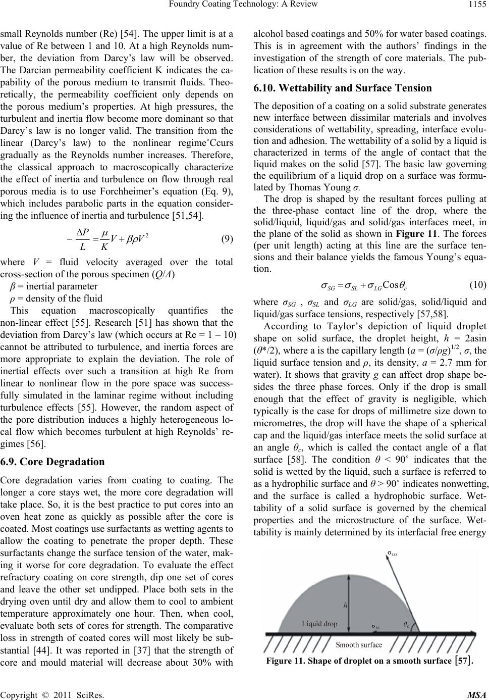 Foundry Coating Technology: A Review1155 small Reynolds number (Re) [54]. The upper limit is at a value of Re between 1 and 10. At a high Reynolds num- ber, the deviation from Darcy’s law will be observed. The Darcian permeability coefficient K indicates the ca- pability of the porous medium to transmit fluids. Theo- retically, the permeability coefficient only depends on the porous medium’s properties. At high pressures, the turbulent and inertia flow become more dominant so that Darcy’s law is no longer valid. The transition from the linear (Darcy’s law) to the nonlinear regime˚Ccurs gradually as the Reynolds number increases. Therefore, the classical approach to macroscopically characterize the effect of inertia and turbulence on flow through real porous media is to use Forchheimer’s equation (Eq. 9), which includes parabolic parts in the equation consider- ing the influence of inertia and turbulence [51,54]. 2 PVV LK (9) where V = fluid velocity averaged over the total cross-section of the porous specimen (Q/A) β = inertial parameter ρ = density of the fluid This equation macroscopically quantifies the non-linear effect [55]. Research [51] has shown that the deviation from Darcy’s law (which occurs at Re = 1 – 10) cannot be attributed to turbulence, and inertia forces are more appropriate to explain the deviation. The role of inertial effects over such a transition at high Re from linear to nonlinear flow in the pore space was success- fully simulated in the laminar regime without including turbulence effects [55]. However, the random aspect of the pore distribution induces a highly heterogeneous lo- cal flow which becomes turbulent at high Reynolds’ re- gimes [56]. 6.9. Core Degradation Core degradation varies from coating to coating. The longer a core stays wet, the more core degradation will take place. So, it is the best practice to put cores into an oven heat zone as quickly as possible after the core is coated. Most coatings use surfactants as wetting agents to allow the coating to penetrate the proper depth. These surfactants change the surface tension of the water, mak- ing it worse for core degradation. To evaluate the effect refractory coating on core strength, dip one set of cores and leave the other set undipped. Place both sets in the drying oven until dry and allow them to cool to ambient temperature approximately one hour. Then, when cool, evaluate both sets of cores for strength. The comparative loss in strength of coated cores will most likely be sub- stantial [44]. It was reported in [37] that the strength of core and mould material will decrease about 30% with alcohol based coatings and 50% for water based coatings. This is in agreement with the authors’ findings in the investigation of the strength of core materials. The pub- lication of these results is on the way. 6.10. Wettability and Surface Tension The deposition of a coating on a solid substrate generates new interface between dissimilar materials and involves considerations of wettability, spreading, interface evolu- tion and adhesion. The wettability of a solid by a liquid is characterized in terms of the angle of contact that the liquid makes on the solid [57]. The basic law governing the equilibrium of a liquid drop on a surface was formu- lated by Thomas Young σ. The drop is shaped by the resultant forces pulling at the three-phase contact line of the drop, where the solid/liquid, liquid/gas and solid/gas interfaces meet, in the plane of the solid as shown in Figure 11. The forces (per unit length) acting at this line are the surface ten- sions and their balance yields the famous Young’s equa- tion. Cos SG SL LGc (10) where σSG , σSL and σLG are solid/gas, solid/liquid and liquid/gas surface tensions, respectively [57,58]. According to Taylor’s depiction of liquid droplet shape on solid surface, the droplet height, h = 2asin (θ*/2), where a is the capillary length (a = (σ/ρg)1/2, σ, the liquid surface tension and ρ, its density, a = 2.7 mm for water). It shows that gravity g can affect drop shape be- sides the three phase forces. Only if the drop is small enough that the effect of gravity is negligible, which typically is the case for drops of millimetre size down to micrometres, the drop will have the shape of a spherical cap and the liquid/gas interface meets the solid surface at an angle θc, which is called the contact angle of a flat surface [58]. The condition θ < 90˚ indicates that the solid is wetted by the liquid, such a surface is referred to as a hydrophilic surface and θ > 90˚ indicates nonwetting, and the surface is called a hydrophobic surface. Wet- tability of a solid surface is governed by the chemical properties and the microstructure of the surface. Wet- tability is mainly determined by its interfacial free energy Figure 11. Shape of droplet on a smooth surface[57]. Copyright © 2011 SciRes. MSA 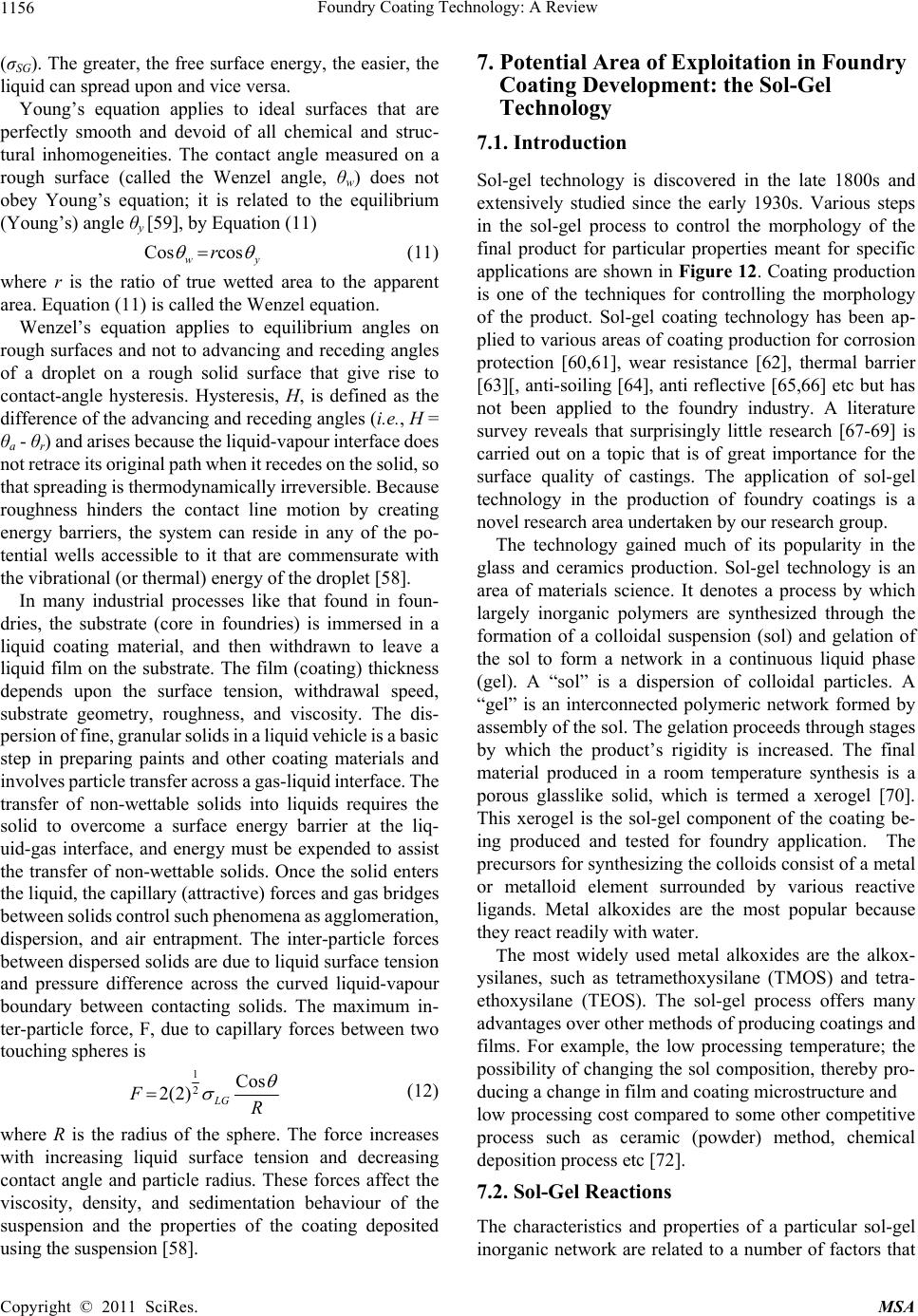 Foundry Coating Technology: A Review Copyright © 2011 SciRes. MSA 1156 y 7. Potential Area of Exploitation in Foundry Coating Development: the Sol-Gel (σSG). The greater, the free surface energy, the easier, the liquid can spread upon and vice versa. Technology Young’s equation applies to ideal surfaces that are perfectly smooth and devoid of all chemical and struc- tural inhomogeneities. The contact angle measured on a rough surface (called the Wenzel angle, θw) does not obey Young’s equation; it is related to the equilibrium (Young’s) angle θy [59], by Equation (11) 7.1. Introduction Sol-gel technology is discovered in the late 1800s and extensively studied since the early 1930s. Various steps in the sol-gel process to control the morphology of the final product for particular properties meant for specific applications are shown in Figure 12. Coating production is one of the techniques for controlling the morphology of the product. Sol-gel coating technology has been ap- plied to various areas of coating production for corrosion protection [60,61], wear resistance [62], thermal barrier [63][, anti-soiling [64], anti reflective [65,66] etc but has not been applied to the foundry industry. A literature survey reveals that surprisingly little research [67-69] is carried out on a topic that is of great importance for the surface quality of castings. The application of sol-gel technology in the production of foundry coatings is a novel research area undertaken by our research group. Cos cos w r (11) where r is the ratio of true wetted area to the apparent area. Equation (11) is called the Wenzel equation. Wenzel’s equation applies to equilibrium angles on rough surfaces and not to advancing and receding angles of a droplet on a rough solid surface that give rise to contact-angle hysteresis. Hysteresis, H, is defined as the difference of the advancing and receding angles (i.e., H = θa - θr) and arises because the liquid-vapour interface does not retrace its original path when it recedes on the solid, so that spreading is thermodynamically irreversible. Because roughness hinders the contact line motion by creating energy barriers, the system can reside in any of the po- tential wells accessible to it that are commensurate with the vibrational (or thermal) energy of the droplet [58]. The technology gained much of its popularity in the glass and ceramics production. Sol-gel technology is an area of materials science. It denotes a process by which largely inorganic polymers are synthesized through the formation of a colloidal suspension (sol) and gelation of the sol to form a network in a continuous liquid phase (gel). A “sol” is a dispersion of colloidal particles. A “gel” is an interconnected polymeric network formed by assembly of the sol. The gelation proceeds through stages by which the product’s rigidity is increased. The final material produced in a room temperature synthesis is a porous glasslike solid, which is termed a xerogel [70]. This xerogel is the sol-gel component of the coating be- ing produced and tested for foundry application. The precursors for synthesizing the colloids consist of a metal or metalloid element surrounded by various reactive ligands. Metal alkoxides are the most popular because they react readily with water. In many industrial processes like that found in foun- dries, the substrate (core in foundries) is immersed in a liquid coating material, and then withdrawn to leave a liquid film on the substrate. The film (coating) thickness depends upon the surface tension, withdrawal speed, substrate geometry, roughness, and viscosity. The dis- persion of fine, granular solids in a liquid vehicle is a basic step in preparing paints and other coating materials and involves particle transfer across a gas-liquid interface. The transfer of non-wettable solids into liquids requires the solid to overcome a surface energy barrier at the liq- uid-gas interface, and energy must be expended to assist the transfer of non-wettable solids. Once the solid enters the liquid, the capillary (attractive) forces and gas bridges between solids control such phenomena as agglomeration, dispersion, and air entrapment. The inter-particle forces between dispersed solids are due to liquid surface tension and pressure difference across the curved liquid-vapour boundary between contacting solids. The maximum in- ter-particle force, F, due to capillary forces between two touching spheres is The most widely used metal alkoxides are the alkox- ysilanes, such as tetramethoxysilane (TMOS) and tetra- ethoxysilane (TEOS). The sol-gel process offers many advantages over other methods of producing coatings and films. For example, the low processing temperature; the possibility of changing the sol composition, thereby pro- ducing a change in film and coating microstructure and 1 2Cos 2(2) LG FR (12) low processing cost compared to some other competitive process such as ceramic (powder) method, chemical deposition process etc [72]. where R is the radius of the sphere. The force increases with increasing liquid surface tension and decreasing contact angle and particle radius. These forces affect the viscosity, density, and sedimentation behaviour of the suspension and the properties of the coating deposited using the suspension [58]. 7.2. Sol-Gel Reactions The characteristics and properties of a particular sol-gel inorganic network are related to a number of factors that  Foundry Coating Technology: A Review 1157 Figure 12. Various steps in the sol-gel process to control the final morphology of the product [71]. affect the rate of hydrolysis and condensation reactions, such as, pH, temperature and time of reaction, reagent concentrations, catalyst nature and concentration, H2O/Si molar ratio (R), aging (structure modifications with time depending on time and temperature, solvent and pH con- ditions) temperature and time, and drying. Of the factors listed above, pH, nature and concentration of catalyst, H2O/Si molar ratio (R), and temperature have been iden- tified as the most important. Thus controlling these fac- tors, it is possible to vary the structure and properties of the sol-gel derived inorganic network over wide ranges. At the functional group level, three reactions are used to describe the sol-gel process: hydrolysis, water condensa- tion and alcohol condensation. Generally speaking, the hydrolysis reaction, through the addition of water, replaces alkoxides groups (-OR) with hydroxyl groups (OH). Subsequent condensation reactions involving the silanol groups (Si-OH), which are hydroxylated species, produce siloxane bonds (Si-O-Si) under release of water (oxolation), whereas the reaction between a hydroxide and an alkoxide leads to siloxane bonds (Si-O-Si) under release of an alcohol (alkoxola- tion). ≡ Si – OR + H2O ≡ Si – OH + ROH This process is called hydrolysis ≡ Si – OH + HO – Si ≡ ≡ Si – O – Si ≡ + H2O This condensation process is called oxolation ≡ Si – OR + HO – Si ≡ ≡ Si – O – Si ≡ + ROH This condensation process is called alkoxolation Under most conditions, condensation starts before hy- drolysis is complete. However, conditions such as, pH, H2O/Si molar ratio (R), and catalyst can force completion of hydrolysis before condensation begins. Additionally, because water and alkoxides are immiscible, a mutual solvent such as an alcohol is utilized. With the presence of this homogenizing agent, alcohol, hydrolysis is facili- tated due to the miscibility of the alkoxides and water. As the number of the siloxane bonds increases, the individ- ual molecules are bridged and jointly aggregate in the sol. When the sol particles aggregate, or inter-knit into a network, a gel is formed. Upon drying, trapped volatiles (water, alcohol, etc.) are driven off and the network shrinks as further condensation can occur. The first step of the hydrolysis of the Silicon alkoxides can occur by acid-catalysed or base-catalysed processes. Mineral acids (HCl) and ammonia are most generally used; however, other catalysts are acetic acid, KOH, amines, KF and HF. It can generally be said that sol-gel derived silicon oxide networks, under acid catalysed conditions, yield primarily linear or randomly branched polymers which entangle and form additional branches resulting in gelation. On the other hand, silicon oxides networks derived under base-catalysed conditions yield more highly branched clusters which do not interpene- trate prior to gelation and thus behave as discrete clusters having larger sol particles and large pores between the interconnected particles. Hence the choice of acid or base catalysis has a substantial influence on the nature of the gel which is formed [49,73]. 7.3. Application of Sol-Gel Process in Foundry Coating Formulation The application of sol-gel coating process in foundry coating production is a novel area of research undertaken by the authors at Technical University of Denmark, DTU and the coating producers at Danish Technological Insti- tute, DTI along with the expertise of the industrial part- ners [48,74]. Chemically bonded sand cores are dip coated with the sol-gel coatings containing different filler materials. The core-coating interactions are investigated Copyright © 2011 SciRes. MSA  Foundry Coating Technology: A Review 1158 using advanced microscopy and spectroscopy. During casting, the thermal behaviour of the coated cores is monitored using a data acquisition soft ware. The mod- eled results for commercial casting modeling and simu- lating soft ware are correlated to experimental results accordingly. After casting, the surface and subsurface quality of the castings are examined with a 3 D optical surface roughness measuring microscope and a scanning electron microscope respectively. The results so far ob- tained show a significant potential in the sol-gel process towards, improvement of the surface quality of casting. 8. Conclusions This is a review about foundry coating technology. It includes but not limited to the coating components, methods of application and characterization parameters. New area of innovation for further development and im- provement of foundry coating technology was also in- troduced. Following the ongoing discussions, this review has thrown more light in the foundry coating technology. The information in this report will help foundries to identify the right parameters to enhance the performance of their coatings to produce castings with excellent sur- face finish. On the other hand foundry coating manufac- turers will find this report highly resourceful for the im- provement of their various existing products. 9. Acknowledgements The authors wish to acknowledge the Danish Agency for Science, Technology and Innovation for their financial support for the ongoing project. REFERENCES [1] T. A. Burns, “The Foseco Foundryman's Hanbook,” Per- gamon Press, Staffordshire, 1986. [2] I. D. Kascheev, N. Yu. Novozhilov, E. V. Tsarevskii, V. A. Perepelitsyn, V. A. Ryabin and N. F. Seliverstov, “Re- fractory Coatings for Foundry Moulds and Cores,” Journal of Refractories and Ceramics, Vol. 23, 1982, pp. 36-139. [3] AFS, “Moulding Methods and Materials,” 1st Edition, The Ameriacan Foundrymen’s Society, Illonois, 1962. [4] S. D. Chastain, “A Sand Casting Manual for the Small Foundry,” Jacksonvile Publishers, Florrida, Vol. 1, 2004. [5] L. Horvath, “Coatings Go Beyond Appearance to Provide Quality Control,” 2010. http://www.Foundrymag.com/Classes/Article/articledraw. Aspx. [6] F. W. Pursall, “Coatings for Moulds and Cores,” K. Straus, Ed., Applied Science in the Casting of Metals, Pergamon Press, Oxford, 1970. [7] R. E. Moore, “Refractories, Structure and Properties,” Encyclopedia of Materials: Science and Technology, 2001, pp. 8079-8099. [8] F. L. Pirkle, D. A. Podmeyer, “Zircon: Origin and Uses,” Society for Mining, Metallurgy and Exploration, Vol. 292. http://cam.usf.edu/CAM/exhibitions/1998_12_McCollum /supplemental_didactics/62.Zircon.pdf [9] J. Hlavac, “Melting Temperatures of Refractory Oxides,” Pure and Applied Chemistry, Vol. 54, No. 3, 1982, pp. 681-688. doi:10.1351/pac198254030681 [10] C. E. Houssa, “Minerals in Plastics,” Bulletin de la Societe Royale des sciences de liege, Vol. 72, 2003, pp. 71-80. [11] J. R. Brown, “The Foseco Foundryman’s Handbook”, Pergamon Press, Oxford, 2000. [12] S. Derbyshire, “Coating Composition,” US patent, 4279, 946, 1981. http://www.freepatentsonline.com/4279946 [13] J. J. Horak, “Core and Mould Wash,” US patent 075, 1990. http://www.freepatentsonline.com/1990075 [14] G. D. Ulrich and D. W. Molesky, “Silica Fillers from Silicon Powder,” US Patent 4, 755, 368, 1988. http://www.osti.gov/energycitations/product.biblio [15] N. A. Waterman, R. Trubshaw and A. M. Pye, “Filled thermoplastic Materials Part 1: Fillers and Compounds,” International journal of Materials in Engineering Appli- cations, Vol. 1, No. 2, 1978, pp. 74-79. doi:10.1016/S0141-5530(78)90036-5 [16] K. W. Jang, W. S. Kwon, M. J. Yim and K. Paik, “Effects of Silica Filler and Diluent on Materials Properties of Non-Conductive Paste and thermal Cycling reliability of Flip Chip Assembly,” Microelectronics and packaging Society, Vol. 10, 2003, pp. 1-9. [17] P. L. Jain, “Principle of Foundry Technology,” 4th Edition, McGraw-Hill, New Delhi, 2006. [18] F.O. Traenkner, “Surface Treatments of Moulds,” US Patent 2,618,032, 1952. http://www.freepatentsonline.com/2618032 [19] J. W. G. Wells, “Olivine Uses and Beneficiation Meth- ods,” NCSU Minerals Laboratoty Bull, Vol. 2, 1959. http://www.p2pays.org/ref/49/48621 [20] M. Yekeler, U. Ulusoy and C. Hicyilmaz, “Effect of Par- ticle Shape and Roughness of Talc Mineral Around by Different Mills on the Wettability and Floatability,” Powder Technology, Vol. 140, No. 12, 2004, pp. 68-78. doi:10.1016/j.powtec.2003.12.012 [21] Z. S. Aćimović-Pavlović, A. K. Prstić and L. D. Andrić, “The Characterization of Talc-Based Coating for Appli- cation for Al-Si Alloy Casting,” Chemical Industry and Chemical Engineering Quarterly, Vol. 13, No. 1, 2007, pp. 38-40. [22] K. S. Ariffin, “Talc and Pyrophylite Group–2:1 Phyl- losilicate,” EBS 425–Mineral Perindustria, pp. 1-21, 2000. http://mineral.eng.usm.my/web%20halaman%20mineral/ Talc%20and%20pyrohyllite [23] D. Gan, S. Lu, C. Song and Z. Wang, “Physical Properties of Poly(Ether Ketone Ketone)/Mica Composites: Effect of Filler Content,” Materials Letters, Vol. 48, No. 5, 2001, pp. 299-302. doi:10.1016/S0167-577X(00)00318-9 [24] M. Zone, “Mica,” 2010. Copyright © 2011 SciRes. MSA  Foundry Coating Technology: A Review1159 http://www.Mineralszone.com/minerals/mica.Html. [25] W. B. Parkes, “Clay-Bonded Foundry Sand,” ASP, Eng- land, 1971. [26] A. Astruc, E. Joliff, J. F. Chailan, E. Aragon, C. O. Petter and C. H. Sampaio, “Incorporation of Kaolin Fillers into an Epoxy/Polyamidoamine Matrix for Coatings ,” Pro- gress in Organic Coatings, Vol. 65, No. 1, 2009, pp. 158- 168. doi:10.1016/j.porgcoat.2008.11.003 [27] W. M. Bundy and J. N. Ishley, “Kaolin in paper filling and coating,” Scholars Portal Journals, Vol. 5, No. 1, 1991, pp. 397-420. doi: 10.1016/0169-1317(91)90015-2 [28] B. W. Rowland, “Modified Clay,” US patent 2,307,239, 2006. http://www.google.com/patents? [29] M. Swartzlander, “Refractory Coating: Making the Right Choice,” Modern Casting, 1992. http://www.allbusiness.com/manufacturing/fabricated-me tal-product-manufacturing/340970-1.html [30] J. Koller and B. Schmitt, “The Challenge: Decrease the Drying Time for Wash Coatings on Sand Moulds and Cores,” The EPRI Center for Materials Production. CMP-091. http://www.p2pays.org/ref/09/08993 [31] J. L. Leblane, “Rubber-Filler Interactions and Rheological Properties in Filled Compounds,” Progress in Polymer Scence, Vol. 27, No. 4, 2002, pp. 627-687. doi:10.1016/S0079-6700(01)00040-5 [32] EPA “Self-Audit and Inspection Guide: Organic Finishing of Metals,” 2010. http://www.Paintcenter.org/ctc/applimeth.Cfm. [33] C. J. Brinker, G. C. Frye, A. J. Hurd and C. S. Ashley, “Ashley Fundamentals of Sol-Gel Dip Coating,” Thin Solid Films, Vol. 201, No. 5, 1991, pp. 97-108. doi:10.1016/0040-6090(91)90158-T [34] A. C. Psimenos and G. Eder, “PCT-Pure Coating Tech- nology,” 2011. http://kongre.tudoksad.org.tr/assets/Uploads/31.GunterEd er-word.pdf. [35] YTCA’s, “Anti-Reflection Coating Technology,” 2010. http://www.ytca.com/dip_coating. [36] S. Brannon, M. McElrath, R. Reddy and S. R. Counselor, “Navigating the Ripples of Flow Coating,” Modern Cast- ing, pp. 29-31, 2009. [37] Gietech BV ir Henderieckx, “Coatings for Chemical Bounded Sand,” 2005. http://www.gietech.be/LinkClick.aspx?fileticket=l6MCLo ftoMI%3D&tabid=111&mid=539 [38] Y. P. Yakunin, G. A. Ponomarevn and E. V. Shtyrenkov, “Experience in the Preparation of Self-Drying Sand-Bur- ning Resistant Coatings for Foundry Moulds and Cores,” US Patent UDC 678.026.3. [39] J. Kroker, “Casting solutions,” 2010. http://www.ductile.org/magazine/2003_3/nbriefs.htm [40] Case Study, “Aluminium Foundry replaces TCA with Water-based Coatings,” 2010 http://www.p2pays.org/ref/05/04239.htm. [41] Canadian Foundry Association, “Guide to Energy Effi- ciency Opportunities in Canadian Foundries,” 2003. http://oee.rncan.gc.ca/cipec/ieep/newscentre/foundry/2/2_ 3_5.cfm?attr=29. [42] Cast TIP, “Controlling Refractory Coatings,” Modern Casting, 2010. http://www.thefreelibrary.com/Controlling+refractory+co atings.-a022 [43] Shamlax Meta-chem Private, “Colour Changing Zircon Foundry Coatings,” 2003. http://www.tradeindia.com/fp442828/Color-Changing-Zir con-Foundry-Coatings.html [44] S. G. Baker, “Evaluating Refractory Coatings: a Practical Approach,” Modern Casting, Vol. 92, 2002, pp. 21-23. [45] N. Hodgkinson, “Improved Ductile Iron Casting Quality Through Optimized Coating Technology,” The Ductile Iron News, 2004. http://www.ductile.org/magazine/2004_1/coating.htm [46] L. Winardi and R. D. Griffin, “Effects of Coating Drying Methods on LOI, Gas Evolution and Core Permeabil- ity,”AFS Transactions Paper, Vol. 08-047, 2008. [47] S. N. Ramrattan and M. K. Joyce, “Final Report-Refractory Coating Control,” http://amc.aticorp.org/reports/wmu2009.pdf. [48] U. C. Nwaogu, T. Poulsen, R. Stage, C. Bischoff and N. S. Tiedje, “New Sol-Gel Refractory Coatings on Chemi- cally-Bonded Sand Cores for Foundry Applications to Improve Casting Surface Quality,” Science and Coatings Technology, Vol. 205, No. 16, 2011. doi:10.1016/j.surfcoat.2011.02.042 [49] J. D. Wright and N. A. J. M. Sommerdijk, “Sol-Gel Ma- terials Chemistry and Applications,” CRC Press, London, 2001. [50] BAMR (Pty), “Elcometer Wet Film Combs,” 2011. http://www.bamr.co.za/elcometer%203238%20long%20e dge%20wet%20film%20comb.shtml. [51] X. Chen, “Permeability Measurement and Numerical Modelling for Refractory Porous Materials,” American Foundry Society Transactions Paper, Vol. 08-133, 2008. [52] W. A. Anderson, “Permeability Relationships Using Darcy Permeability, Vacuum Decay, Pressure Decay, and Pore Size Distribution Methods on Graphitic Materials,” Carbon, Vol. 4, No. 1, 1966, pp. 107-114. doi:10.1016/0008-6223(66)90015-7 [53] T. Sogabe, M. Inagaki and T. Ibuki, “Coating of Graphite by Polyimide and Its Gas Permeability,” Carbon, Vol. 30, No. 3, 1992, pp. 513-516. doi:10.1016/0008-6223(92)90051-W [54] X. H. Wang and Z. Liu, “The Forchheimer Equation in Two-Dimensional Percolation Porous Media,” Physical A: Statical and Theoretical Phycics, Vol. 337, No. 3-4, 2004, pp. 384-388. doi:10.1016/j.physa.2004.01.047 [55] U. M. S. Costa, J. S. Andrade Jr, H. A. Makse and H. E. Stanley, “The Role of Inertia on Fluid Flow through Dis- ordered Porous Media,” Physical A: Statistical Mechanics and Its Applications, Vol. 266, No. 1-4, 1999, pp. 420-424. doi:10.1016/S0378-4371(98)00624-4 [56] H. H. Macedo, U. M. S. Costa and M. P. Almeida, “Tur- Copyright © 2011 SciRes. MSA  Foundry Coating Technology: A Review Copyright © 2011 SciRes. MSA 1160 bulent Effects on Fluid Flow through Disordered Porous Media,” Physical A: Statistical Mechanics and Its Appli- cations, Vol. 299, No. 1-4, 2001, pp. 371-377. doi:10.1016/S0378-4371(01)00257-6 [57] A. W. Neumann and R. J. Good, Surface and Colloid Science, Vol. 2, 1979. [58] Z. Lijun, W. Xuedong, L. Zeng and W. Dan, “Superhy- drophobicity from Microstructured Surface,” Chinese science Bulletin, Vol. 49, No. 17, 2004, pp. 1779-1787. doi:10.1007/bf03183400 [59] R. Asthana and S. S. T. Mileiko, “Wettability and Inter- facial Considerations in Advanced Heat-Resistant Ni-base Composites,” Bulletin of the Polish Academy of Sciences, Technical Sciences, Vol. 54, 2006. [60] P. Kiruthika, R. Subasri, A. Jyothirmayi, K. Sarvani and N. Y. Hebalkar, “Effect of Plasma Surface Treatment on Mechanical and Corrosion Protection Properties of UV-Curable Sol-Gel based GPTS-ZrO2 Coatings on Mild Steel,” Surface and Coatings Technology, Vol. 204, No. 6, 2010, pp. 1270-1276. doi:10.1016/j.surfcoat.2009.10.017 [61] A. L. K. Tan, A. M. Soutar, I. F. Annergreen and Y. N. Liu, “Multilayer Sol-Gel Coatings for Corrosion Protection of Magnesium,” Surface and Coatings Technology, Vol. 198, No. 1-3, 2005, pp. 478-482. doi:10.1016/j.surfcoat.2004.10.066 [62] T. Hübert, S. Svoboda and B. Oertel, “Wear Resistant Alumina Coatings Produced by a Sol-Gel Process,” Sur- face and Coatings Technology, Vol. 201, No. 1-2, 2006, pp. 487-491. doi:10.1016/j.surfcoat.2005.11.014 [63] C. Viazzi, J. P. Bonino and F. Ansart, “Synthesis by sol-gel Route and Characterization of Yttria Stabilized Zircinia Coatings for Thermal Barrier Applications,” Sur- face and Coatings Technology, Vol. 201, No. 7, 2006, pp. 3889-3893. doi:10.1016/j.surfcoat.2006.07.241 [64] K. H. Hass, S. Amberg-Schwab, K. Rose and G. Schottner, “Functionalized Coatings Based on Inorganic-Organic Polymers (ORMOCER ®s) and Their Combination with vapor Deposited Inorganic Thin Films,” Surface and Coatings Technology, Vol. 111, No. 1, 1999, pp. 72-79. doi:10.1016/S0257-8972(98)00711-7 [65] C. Guillén, A. Morales and J. Herrero, “Performance of Sol-Gel SiO2 Coatings onto Glass/SnO2 Superstrates,” Surface and Coating Technology, Vol. 132, No. 1, 2000, pp. 31-35. doi:10.1016/S0257-8972(00)00727-1 [66] D. R. Uhlmann, T. Suratwala, J. K. Davidson, M. Boulton and G. Teowee, “Sol-Gel Coatings on Glass,” Journal of Non-Crystalline Solids, Vol. 318, 1997, pp. 113-122. doi:10.1016/S0022-3093(97)00162-2 [67] T. B. N. Hodgkinson, “Improving Foundry Profitability through the Use of Rheotec* XL Coating,” Foseco Foun- dry Practice, Vol. 240, 2003. [68] T. Birch and D. Bell, “Improved Iron Casting Quality through Application of Advanced Coating Technology,” Foseco Foundry Practice, Vol. 243, 2005. [69] A. Schrey, “NORACEL* w100 - A New Technology to Prevent Veining Defects,” Foseco Foundry Practice, Vol. 246, 2007. [70] J. B. Laughlin, J. L. Sarquis, V. M. Jones and J. A. Cox, “Using Sol-Gel Chemistry to Synthesize a Material with properties Suited for Chemical Sensing,” Journal of Chemical Education, Vol. 77, No. 1, 2000, pp. 77-79. doi:10.1021/ed077p77 [71] M. Niederberger and N. Pinna, “Metal Oxide Nanoparticles in Organic Synthesis,” Formation, Assembly and Appli- cation, Vol. XIII, No. 217, 2009. [72] S. M. Tracey, S. N. B. Hodgson, A. K. Ray and Z. Ghas- semlooy, “The Role and Interactions of Process Parame- ters on the Nature of Alkoxides Derived Sol-Gel Films,” Journal of Materials Processing Technology, Vol. 77, No. 1-3, 1998, pp. 86-94. doi:10.1016/S0924-0136(97)00399-3 [73] K. Mauritz, “Sol-Gel Chemistry,” http://www.psrc.usm.edu/mauritz/solgel.html. [74] U. C. Nwaogu, T. Poulsen, C. Bischoff and N. S. Tiedje, “Influence of New Sol-Gel Refractory Coating on the Casting Properties of Cold Box and Furan Cores for Grey Cast Iron,” The Proceedings of 69th World Foundry Con- gress, Hangzhou, 16-20 October 2010, pp. 648-653. |