Paper Menu >>
Journal Menu >>
 Materials Sciences and Application, 2011, 2, 1027-1032 doi:10.4236/msa.2011.28139 Published Online August 2011 (http://www.SciRP.org/journal/msa) Copyright © 2011 SciRes. MSA 1027 Crack-Tip Stress Analysis at a Bi-Material Interface by Photoelastic, Isopachic and FEA George A. Papadopoulos1*, Elen B. Bouloukou1, Elen G. Papadopoulou2 1National Technical University of Athens, Department of Engineering Science, Section of Mechanics, Zografou campus, Athens, Greece; 2National Technical University of Athens, Department of Mining Engineering and Metallurgy, Laboratory of physical Met- allurgy, Athens, Greece. Email: *gpad@central.ntua.gr, papadel@central.ntua.gr Received April 30th, 2011; revised May 25th, 2011; accepted June 2nd, 2011. ABSTRACT The paper investigates the stress state at the bi-material interface crack-tip by the Photoelastic and Isopachic methods and the Finite Element Analysis (FEA). The principal stresses at the bi-material interface crack-tip are theoretically determined using the combination photoelastic and isopachic fringes. The size and the shape of crack-tip isochromatic and isopachic fringes, at a bi-material interface under static load, are studied. When the crack-tip, which is perpen- dicular to interface, is placed at the interface of the bi-material, the isochromatic and the isopachic fringes depend on the properties of the two materials. Thus, the isochromatic and the isopachic fringes are divided into two branches, which present a jump of values at the interface. The size of the two branches mainly depends on the elastic modulus and the Poisson’s ratio of the two materials. From the combination of the isochromatic and the isopachic fringes, the prin- cipal stresses σ1 and σ2 can be estimated and the contour curves around the crack-tip can be plotted. For the FEA analysis, the program ANSYS 11.0 was used. The bi-material cracked plates were made from Lexan (BCBA) and Plexi- glas (PMMA). Keywords: Crack, Bi-Material, Photoelasticity, Isochromatic, Isopachic, FEA 1. Introduction The study of the behaviour of a transverse crack propa- gating through the mesophase of composites has become a subject of great interest. The problem of crack propaga- tion in a duplex plate was studied by Williams et al. [1-5] and later was approached by Dally and Kobayashi [6] by means of dynamic photoelasticity. Theocaris et al. [7-9] have studied the influence of both the mesophase and the material characteristics of either phase, in biphase plates consisting of different materials, on the stress distribution around the crack tip. They have extended their study to the magnitude and the variation of the crack propagation velocities during fracture in duplex plates under dynamic loading [10]. Also, Theocaris et al. [11,12] have studied the influence of the hard or soft fiber and the mesophase layers in a soft-hard-soft or hard-soft-hard combination of biphase plate subjected to a dynamic tensile load, on the fracture mode and bifurcation process in both phases. Also, theoretical studies on this subject were carried out by Gdouto s et al. [13- 15] and Theo tokoglou et al. [16,17]. The study of the size and the shape of crack-tip caustics at a bi-material interface was carried out by Papadopou- los [18]. Sadowski et al. [19,20] have studied the bi-material interface problem for ceramic materials by FEA. In the present paper, we estimate the principal stresses and its contour curves at the bi-material interface crack-tip from the combination of the isochromatic and the isopachic fringes and the FEA. 2. Crack-Tip Stresses at the Interface Two plates of module E1 and E2 and Poisson’s ratio ν1 and ν2 are perfectly bonded along their common interface (Figure 1). In plate (1) there is a crack perpendicular to the interface. The crack-tip is placed exactly at the inter- face of the two plates. The Airy stress function X(r,θ) for this problem, used by Zak and Williams [5], is: 1 (, )( )Xrr F (1) with: sin1cos 1 sin 1cos 1 Fb cd (2) 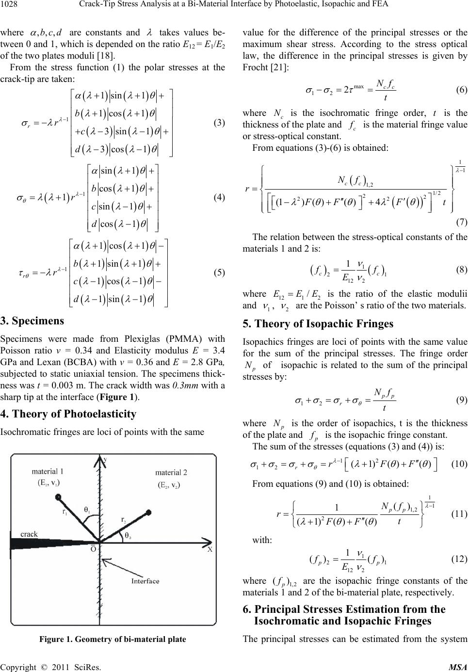 Crack-Tip Stress Analysis at a Bi-Material Interface by Photoelastic, Isopachic and FEA 1028 where ,,,bc d are constants and takes values be- tween 0 and 1, which is depended on the ratio E12 = E1/E2 of the two plates moduli [18]. From the stress function (1) the polar stresses at the crack-tip are taken: 1 1sin 1 1cos1 3sin 1 3cos1 r b r c d (3) 1 sin 1 cos 1 1sin 1 cos 1 b r c d (4) 1 1cos1 1sin 1 1cos1 1sin 1 r b r c d (5) 3. Specimens Specimens were made from Plexiglas (PMMA) with Poisson ratio ν = 0.34 and Elasticity modulus E = 3.4 GPa and Lexan (BCBA) with ν = 0.36 and E = 2.8 GPa, subjected to static uniaxial tension. The specimens thick- ness was t = 0.003 m. The crack width was 0.3mm with a sharp tip at the interface (Figure 1). 4. Theory of Photoelasticity Isochromatic fringes are loci of points with the same Figure 1. Geometry of bi-material plate value fors or the the difference of the principal stresse maximum shear stress. According to the stress optical law, the difference in the principal stresses is given by Frocht [21] : max 12 2cc Nf t (6) where is the isochromatic fringe order, is the obtained: c N ss otgthickne f the plate and c f is the material frine value or stress-optical constant. From equations (3)-(6) is 1 1 1,2 1/2 22 22 (1)()( )4 cc Nf r FFF t (7) The relation between the stress-optical constants of m the aterials 1 and 2 is: 1 2 12 2 1 cc 1 f f E (8) where 121 2 /EEE is the ratio of the elastic modulii and 1 , 2 are the Poisson’ s ratio of the two materials. 5. Theory of Isopachic Fringes Isopachics fringes are loci of points with the same value for the sum of the principal stresses. The fringe order p N of isopachic is related to the sum of the principal sses by: stre 12 p p r Nf t (9) where p N late is the order of isopachics, t is the thickness of the p and p f is the isopachic fringe constant. The sum of theresses (equations (3) and (4)) is: st 12 (1)() ()rFF 12 r (10) From equations (9) and (10) is obtained: 1 1 1,2 2 () 1 (1)() () pp Nf rt FF (11) with: 1 21 12 2 1 () () p p f f E (12) where are the isopachic fringe constants of the Thystem 1,2 () p f materials 1 and 2 of the bi-material plate, respectively. 6. Principal Stresses Estimation from the Isochromatic and Isopachic Fringes e principal stresses can be estimated from the s Copyright © 2011 SciRes. MSA 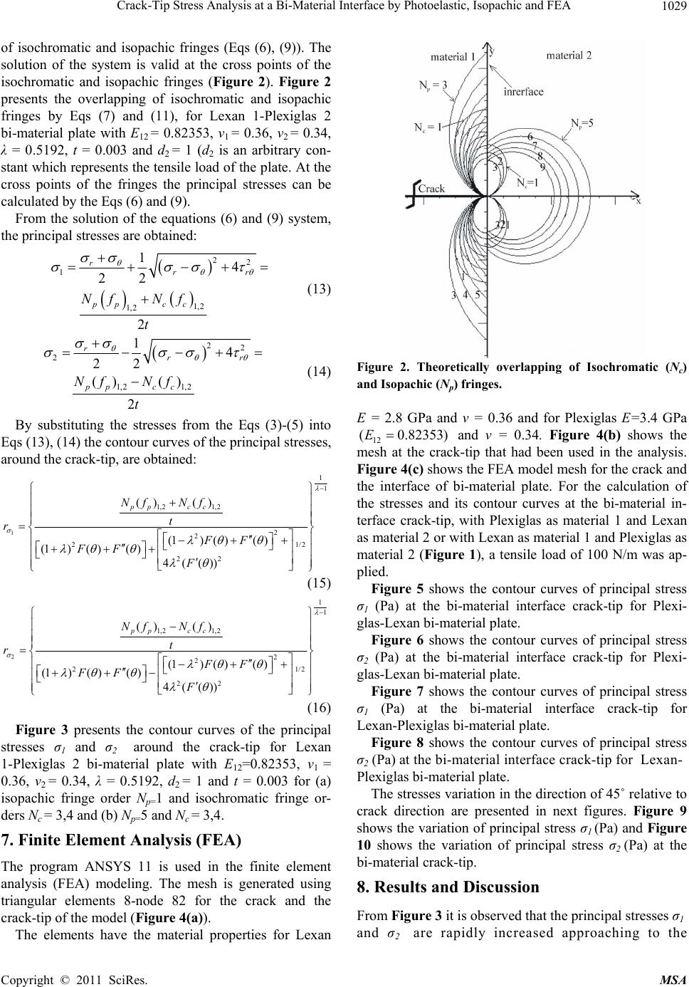 Crack-Tip Stress Analysis at a Bi-Material Interface by Photoelastic, Isopachic and FEA1029 (6) and (9) system, th of isochromatic and isopachic fringes (Eqs (6), (9)). The solution of the system is valid at the cross points of the isochromatic and isopachic fringes (Figure 2). Figure 2 presents the overlapping of isochromatic and isopachic fringes by Eqs (7) and (11), for Lexan 1-Plexiglas 2 bi-material plate with E12 = 0.82353, ν1 = 0.36, ν2 = 0.34, λ = 0.5192, t = 0.003 and d2 = 1 (d2 is an arbitrary con- stant which represents the ten sile load of the plate. At the cross points of the fringes the principal stresses can be calculated by the Eqs (6) and (9). From the solution of the equations e principal stresses are obtained: 22 1 1,2 1,2 1 r 4 22 2 rr pp cc Nf Nf t (13) 22 2 1,21,2 14 22 () () 2 r rr pp cc Nf Nf t (14) By substituting the stresses from the Eqs (3)-(5) into Eqs (13), (14) the contour curves of the principal stresses, around the crack-tip, are obtained: 1 1 1 1,2 1,2 2 2 2 22 () () (1)( )() (1)( )( )4(()) pp cc Nf Nf t r FF FF F 1 /2 (15) 2 1 1 1,2 1,2 2 2 21/2 22 () () (1)()( ) (1)( )()4(()) pp cc Nf Nf t r FF FF F (16) Figure 3 presents the contour curves of the prin st ) finite element roperties for Lexan cipal resses σ1 and σ2 around the crack-tip for Lexan 1-Plexiglas 2 bi-material plate with E12=0.82353, ν1 = 0.36, ν2 = 0.34, λ = 0.5192, d2 = 1 and t = 0.003 for (a) isopachic fringe order Np=1 and isochromatic fringe or- ders Nc = 3,4 and (b) Np=5 and Nc = 3,4. 7. Finite Element Analysis (FEA The program ANSYS 11 is used in the analysis (FEA) modeling. The mesh is generated using triangular elements 8-node 82 for the crack and the crack-tip of the model (Figure 4(a)). The elements have the material p Figure 2. Theoretically overlapping of Isochromatic (Nc) = 2.8 GPa and ν = 0.36 and for Plexiglas E=3.4 GPa and Isopachic (Np) fringes. E 12 ( 0.82353)E and ν = 0.34. Figure 4(b) shows the k-tip that had been used in the analysis. Figure 4(c) shows the FEA model mesh for the crack and the interface of bi-material plate. For the calculation of the stresses and its contour curves at the bi-material in- terface crack-tip, with Plexiglas as material 1 and Lexan as material 2 or with Lexan as material 1 and Plexiglas as material 2 (Figure 1), a tensile load of 100 N/m was ap- plied. Figu mesh at the crac re 5 shows the contour curves of principal stress σ1 r curves of principal stress σ2 r curves of principal stress σ1 of principal stress σ2 he direction of 45˚ relative to cr cussion the principal stresses σ1 (Pa) at the bi-material interface crack-tip for Plexi- glas-Lexan bi-material plate. Figure 6 shows the contou (Pa) at the bi-material interface crack-tip for Plexi- glas-Lexan bi-material plate. Figure 7 shows the contou (Pa) at the bi-material interface crack-tip for Lexan-Plexiglas bi-material plate. Figure 8 shows the contour curves (Pa) at the bi-material interface crack-tip for Lexan- Plexiglas bi-material plate. The stresses variation in t ack direction are presented in next figures. Figure 9 shows the variation of principal stress σ1 (Pa) and Figure 10 shows the variation of principal stress σ2 (Pa) at the bi-material crack-tip. 8. Results and Dis From Figure 3 it is observed that and σ2 are rapidly increased approaching to the Copyright © 2011 SciRes. MSA 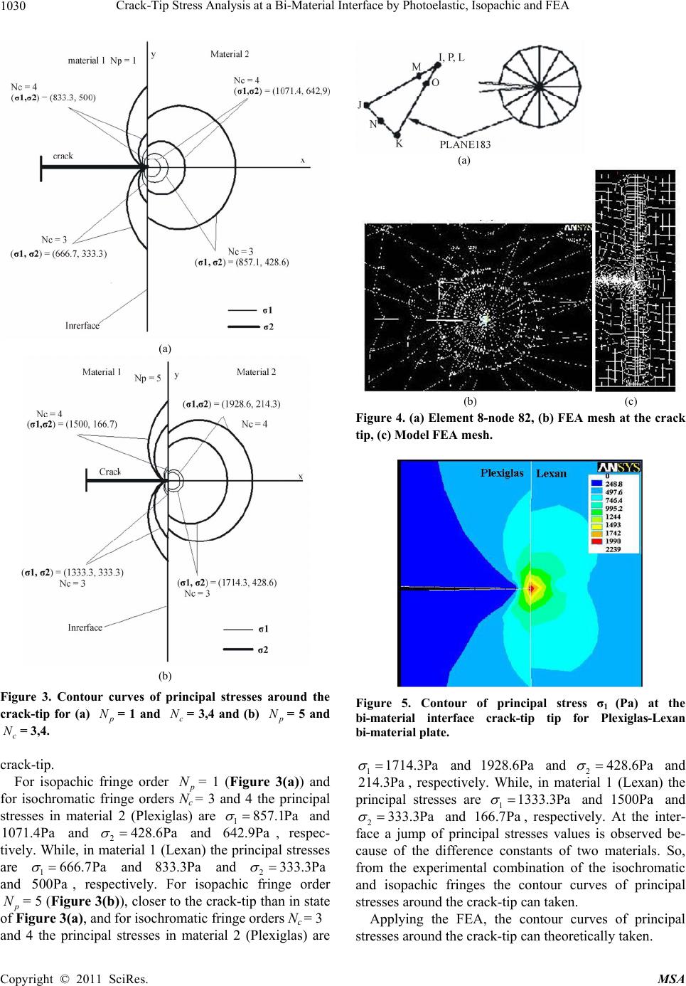 Crack-Tip Stress Analysis at a Bi-Material Interface by Photoelastic, Isopachic and FEA 1030 (a) (b) Figure 3. Contour curves oincipal stresses around the f pr crack-tip for (a) p N = 1 and c N = 3,4 and (b) p N = 5 and c N = 3,4. rack-tip. achic fringe order cFor isop p N Nc = (a) (b) (c) Figure 4. (a) Elemee crack nt 8-node 82, (b) FEA mesh at th tip, (c) Model FEA mesh. Figure 5. Contour of principal stress σ1 (Pa) at the bi-material interface crack-tip tip for Plexiglas-Lexan bi-material plate. and and 1928.6Pa 24 28.6Pa rial 1 (Lexan 11714.3Pa and 214.3Pa , respe principal ctivelyin mate) the stresses are 11333.3Pa . While, and 1500Pa and 2333.3Pa and 166 ively. ter- f principal stsses values is observed be- cause of the difference constants of two materials. So, from the experimental combination of the isochromatic and isopachic fringes the contour curves of principal stresses around the crack-tip can taken. Applying the FEA, the contour curv .7Pa , resp re ectAt the in face a jump o = 1 (Figure 3(a)) and for isochromatic fringe orders 3 and 4 the principal stresses in material 2 (Plexiglas) are 1857.1Pa and 1071.4Pa and 2428.6Pa and 6pec- ile, in man) th are 1666.7 Pa 42.9Pa , res e principal stresses tively. Whaterial 1 (Lex and 833.3Pa and 2333.3Pa and opachi 500Pa , respectively. For isc fringe order p N= 5 (ure 3(b)), closer to the crack-tip than in state igure 3(a), and for isochromatic fringe orders Nc = 3 and 4 the principal stresses in material 2 (Plexiglas) are Fi of F g es of principal stresses around the crack-tip can theoreticall y tak e n. Copyright © 2011 SciRes. MSA 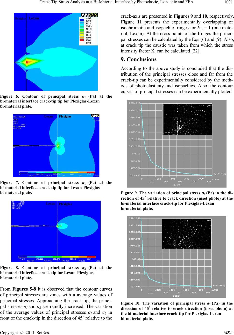 Crack-Tip Stress Analysis at a Bi-Material Interface by Photoelastic, Isopachic and FEA1031 Figure 6. Contour of principal stress σ2 (Pa) at the bi-material interface crack-tip tip for Plexiglas-Lexan bi-material plate. Figure 7. Contour of principal stress σ1 (Pa) at the bi-material interface crack-tip tip for Lexan-Plexiglas bi-material plate. Figure 8. Contour of principal stress σ2 (Pa) the rom Figures 5-8 it is observed that the contour curves study is concluded that the dis- at bi-material interface crack-tip for Lexan-Plexiglas bi-material plate. F of principal stresses are zones with a average values of principal stresses. Approaching the crack-tip, the princi- pal stresses σ1 and σ2 are rapidly increased. The variation of the average values of principal stresses σ1 and σ2 in front of the crack-tip in th e direction of 45˚ relative to the crack-axis are presented in Figures 9 and 10, respectively. Figure 11 presents the experimentally overlapping of isochromatic and isopachic fring es for E12 = 1 (one mate- rial, Lexan). At the cross points of the fringes the princi- pal stresses can be calculated by the Eqs (6) and (9). Also, at crack tip the caustic was taken from which the stress intensity factor KI can be calculated [22]. 9. Conclusions According to the above tribution of the principal stresses close and far from the crack-tip can be experimentally considered by the meth- ods of photoelasticity and isopachics. Also, the contour curves of principal stresses can be experimentally plotted Figure 9. The variation of principal stress σ1 (Pa) in the di- rection of 45˚ relative to crack direction (inset photo) at the bi-material interface crack-tip for Plexiglas-Lexan bi-material plate. Figure 10. The variation of principal stress σ2 (Pa) in the bi-material plate. direction of 45˚ relative to crack direction (inset photo) at the bi-material interface crack-tip for Plexiglas-Lexan Copyright © 2011 SciRes. MSA 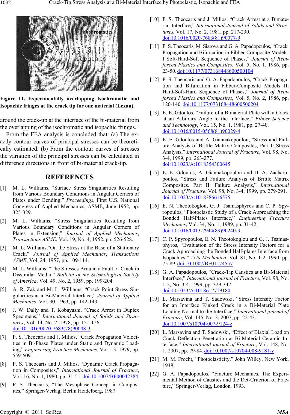 Crack-Tip Stress Analysis at a Bi-Material Interface by Photoelastic, Isopachic and FEA Copyright © 2011 SciRes. MSA 1032 [10] P. S. Theocaris and J. Milios, “Crack Arrest at a Bimate- rial Interface,” International Journal of Solids and Struc- tures, Vol. 17, No. 2, 1981, pp. 217-230. doi:10.1016/0020-7683(81)90077-9 [11] P. S. Theo caris, M. Siar ova and G . A . Papadopo Propagation and Bifurcation in Fibbeulos, “Crack r-Composite Models: I Soft-Hard-Soft Sequence of Phases,” Journal of Rein- forced Plastics and Composites, Vol. 5, No. 1, 1986, pp. 23-50. doi:10.1177/073168448600500104 [12] P. S. Theocaris and G. A. Papadopoulos, “Crack Propaga- tion and Bifurcation in Fibber-Composite Models II: Hard-Soft-Hard Sequence of Phases,” Journal of Rein- forced Plastics and Composites, Vol. 5, No. 2, 1986, pp. 120-140. doi:10.1177/073168448600500204 [13] E. E. Gdoutos, “Failure of a Bimaterial Plate with a Crack at an Arbitrary Angle to the Interface,” Fib Figure 11. Experimentally overlapping Isochromatic Isopachic fringes at the crack tip for one material (Lexan). [1] M. L. Williamularities Resulting from Various BAngular Corners of oundary Conditions in Angular Corners of eismological Societ of Applied olids and Struc- and around the crack-tip at the interface of the bi- material fromber Science and Technology, Vol. 15, No. 1, 1981, pp. 27-40. doi:10.1016/0015-0568(81)90029-4 [14] E. E. Gdoutos and A. Giannakopoulou, “Stress an ure Analysis of Brittle Matrix Composites, P the overlapping of the isochrom ati c and is opachic fringes. From the FEA analysis is concluded that: (a) The ex- actly contour curves of principal stresses can be theoreti-d Fail- art I: Stress cally estimated. (b) From the contour curves of stresses the variation of the principal stresses can be calculated in difference directions in front of bi-material crack-tip. REFERENCES Analysis,” International Journal of Fracture, Vol. 98, No. 3-4, 1999, pp. 263-277. doi:10.1023/A:1018354300645 [15] E. E. Gdoutos, A. Giann poulos, “Stress and Failure An akopoulou and D. A. Zacharo- alysis of Brittle Matrix Composites. Part II: Failure Analysis,” International Journal of Fracture, Vol. 98, No. 3-4, 1999, pp. 279-291. doi:10.1023/A:1018386616575 [16] E. N. Theotokoglou, G. J. Tsamasphyros and C. P. Spy- ropoulos, “Photoelastic Study of s, “Surface Stress Sing oundary Conditions in Plates under Bending,” Proceedings, First U.S. National Congress of Applied Mechanics, ASME, June 1952, pp. 325-329. [2] M. L. Williams, “Stress Singularities Resulting from Various B a Crack Approaching the Bonded Half-Plates Interface,” Engineering Fracture Mechanics, Vol. 34, No. 1, 1989, pp. 31-42. doi:10.1016/0013-7944(89)90240-3 [17] C. P. Spyropoulos, E. N. Theotokoglou and G phyros, “Evaluation of the Stress In Plates in Extension,” Journal of Applied Mechanics, Transactions ASME, Vol. 19, No. 4, 1952, pp. 526-528. [3] M. L. Williams,“On the Stress at the Base of a Stationary Crack,” Journal of Applied Mechanics, Transaction . J. Tsamas- tensity Factors for a Crack Approaching the Bonded Half-plates Interface from Isopachics,” Acta Mechanica, Vol. 81, No. 1-2, 1990, pp. 75-89. doi:10.1007/BF01174557 [18] G. A. Papadopoulos, “Crack-Tip Caustics at a Bi-Material Interface,” International journal o s y ASME, Vol. 24, 1957, pp. 109-114. [4] M. L. Williams, “The Stresses Around a Fault or Crack in Dissimilar Media,” Bulletin of the Sf Fracture, Vol. 98, No. of America, Vol. 49, No. 2, 1959, pp. 199-204. [5] A. R. Zak and M. L. Williams, “Crack Point Stress Sin- gularities at a Bi-Material Interface,” Journal 1-2, No. 3-4, 1999, pp. 329-342. doi:10.1023/A:1018617719180 [19] L. Marsavina and T. Sadowski, “ for an Interface Kinked CrackStress Intensity Factor in a Bi-Material Plate Mechanics, Vol. 30, 1963, pp. 142-143. [6] J. W. Dally and T. Kobayashi, “Crack Arrest in Duplex Specimens,” International Journal of SLoading Normal to the Interface,” International journal of Fracture, Vol. 145, No. 3, 2007, pp. 22-43. doi:10.1007/s10704-007-9124-z [20] L. Marsavina and T. Sadowski, “Effect of Bi Crack Deflection Penetration at Bi-M tures, Vol. 14, No. 2, 1978, pp. 121-126. doi:10.1016/0020-7683(78)90048-3 [7] P. S. Theocaris and J. Milios, “Crack Prop ties in Bi-Phase Plates under Static axial Load on aterial Ceramic In- agation Veloci- and Dynamic mposites,” International Journal of Fracture Load- terface,” International journal of Fracture, Vol. 148, No. 1, 2007, pp. 79-84. doi:10.1007/s10704-008-9181-y [21] M. M. Frocht, “Photoelasticity,” John Willey, New York, 1948. ing,” Engineering Fracture Mechanics, Vol. 13, 1979, pp. 559-609. [8] P. S. Theocaris and J. Milios, “Dynamic Crack Propaga- tion in Co, [22] G. A. Papadopoulos, “Fracture Mechanics. The Experi- mental Vol. 16, No. 1, 1980, pp. 31-51. doi:10.1007/BF00042384 [9] P. S. Theocaris, “The Mesophase Concept in Compos- ites,” Springer-Verlag, Berlin Heidelberg, 1987. Method of Caustics and the Det-Criterion of Frac- ture,” Springer-Verlag, London, 1993. |

