Optics and Photonics Journal
Vol.06 No.08(2016), Article ID:70320,9 pages
10.4236/opj.2016.68B026
Application of Optical Motion Capture Technology in Power Safety Entitative Simulation Training System
Huimeng Zhang1, Lanxiang Wang2, Shenghui Chu1, Shuo Chen1, Hao Meng1*, Guozhong Liu1*
1College of Instrument Science and Opto-Electronics Engineering, Beijing Information Science & Technology University, Beijing, China
2Beijing Kedong Electric Power Control System Co., Ltd., Beijing, China


Received 4 July 2016; accepted 22 August 2016; published 25 August 2016

ABSTRACT
The safety production is critical to stable development of Chinese electric power industry. With the development of electric power enterprises, the requirements of its employees are also becoming higher and higher. In this paper, an optical motion capture system based on the virtual reality technology is proposed to meet the requirements of the power enterprise for the qualified business ability. Electric power equipment, power equipment model entitative operating environment and the human model are established by electric power simulation unit, ZigBee technology and OpenGL graphics library. The problem of missing feature points is solved by applying the human model driven algorithm and the Kalman filtering algorithm. The experimental results show that it is more accurate to use Kalman filtering algorithm to extract the feature point in tracking process of actual motion capture and real-time animation display. The average absolute error of 3D coordinates is 1.61 mm and the average relative error is 2.23%. The system can improve trainees’ sense of experience and immersion.
Keywords:
Motion Capture, Kalman Filtering, Power Safety Training System, 3D Human Body Mode, VR

1. Introduction
The safety production of electric power enterprise is an important guarantee for the development of the power industry. Hence the power companies put in a lot of manpower and material resources to expand and explore new ideas and new methods while improving their own training of staff security. Traditional electrical safety training focuses mainly on organizing training courses and seminars, etc. Theoretical lectures and multimedia courseware are utilized to organize regularly trainees to observe and practice in the job site to improve the perceptual and practical ability. However, these ways are usually high cost and ineffective. Although onsite training has a good effect, a lot of equipment is electrically operated. There is a risk and uncertainty for the trainees in the actual operation with great limitations.
With the development of Virtual Reality (VR) technology [1], simulation systems using VR technology configure virtual environments, and improve the realism of the training scenes. Simulation training software cannot simulate the real power system environments; meanwhile it is a poor sense of the experience and immersion. With the optical motion capture system and electrical equipment entitative simulation training system, the trainees can feel immersive and the ability of simulation training system can be enhanced. Owing to the immersive simulation training, the system can upgrade the training intelligence level and training efficiency.
2. Constitution and Working Principle of the Power Safety Entitative Simulation Training System
2.1. Constitution of the System
The block diagram of the entitative simulation training system is shown in Figure 1, including N simulation power equipment, optical motion capture units, the host of training system and wireless units. The host of training system transmits the data with simulation power equipment through the wireless units and has an ability of real-time acquiring the working state of simulation power equipment. The host of training system acquires all dynamic or static three-dimensional coordinates of the feature points, such as the infrared reflective balls on trainees’ body by using cable transmission network. The data with the receiving equipment’s state information will be analyzed to obtain the consistency interpretation and description of trainees’ action.
2.2. Optical Motion Capture Units
The schematic diagram of the power safety entitative training system based on optical motion capture [2] is shown in Figure 2 and Figure 3.
Eight motion capture infrared cameras are fixed around the training scene. And the infrared reflective balls are also fixed on the electric power equipment and joint positions of the trainees’ work clothes (shoulder, elbow and hip, knee and ankle, etc.) and the caps. The rule of the camera’s position selection is to ensure that each infrared reflective ball can be simultaneously captured by two or more cameras.
3. Key Algorithm of the Motion Capture Unit
3.1. Establishment of the Virtual 3D Human Body Model and Driving Mechanism
The three-dimensional human body model appearance of this system uses OpenGL [3] graphics library in Visual Studio programming environment to establish the model by multiple cubes. The 14 tracking feature points match the joints of body model as shown in Figure 4.
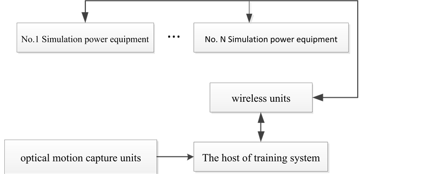
Figure 1. Block diagram of power safety training system.
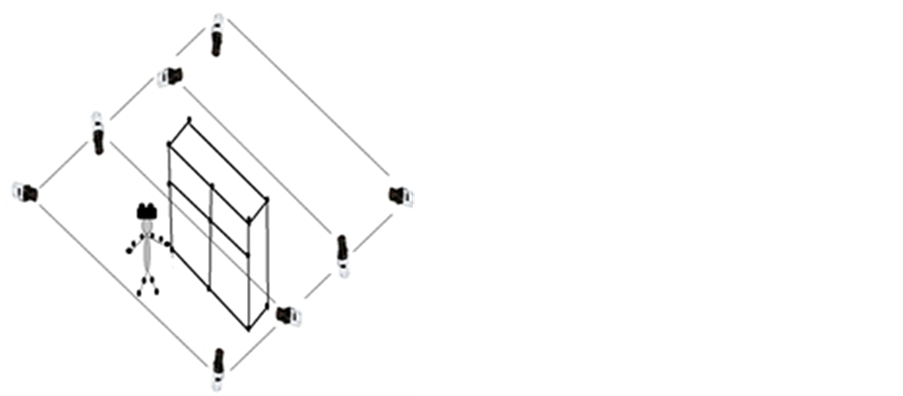
Figure 2. Diagram of motion capture unit.
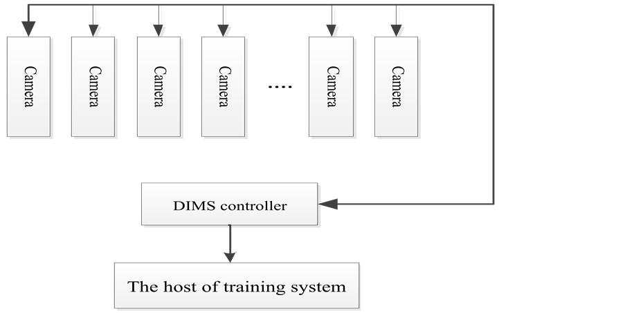
Figure 3. Block diagram of motion capture unit.
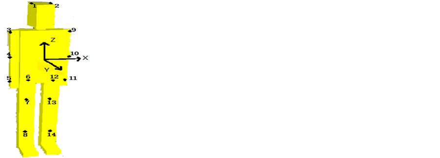
Figure 4. 3D Human model.
In the initial condition, the model of the human body is erect in the experimental scheme, facing the positive direction of Y axis, standing along the positive direction of Z axis.
Anatomy of the human body joint angles is on the basis of the definition of joint surrounding the different axes, sagittal axis (Y axis), frontal axis (X axis), vertical axis (Z axis), and different basic tangent plane, sagittal plane (YZ plane), frontal face (XZ plane), horizontal (XY plane).The calculation method to deal with three dimensional joint angle of the body can be determined by applying space analytic geometry.
(X, Y, Z) is used as the 3D coordinate measurement point in this paper. X, Y, Z axis are respectively used as the three basic axes of the rotary joints. The X, Y, Z axis direction of unit vector is respectively described by  ,
,  ,
,  . The surface of the human body is expressed as S1 (
 is the normal vector of the plane). The sagittal
plane of the human body is expressed as S2 ( is the normal vector of the plane).The frontal plane of human body is expressed as S3 (
 is the normal vector of the plane).
In addition, the calculation of adduction and expand of the upper arm, forearm pronation and supination, according to the actual situation calculation to a joint axis plane of the vector method.
For example, vertical plane with to the upper arm:
 (1)
(1)
Vertical plane with forearm:
 (2)
(2)
Taking shoulder joint as an example to show the calculation method of the joint angle, the angle of the shoulderis defined [4] in Figure 5. These angles can be calculated by the vector of the upper arm in the projection of the basic plane of the human body and the angle of the related basic axis.
 (3)
(3)
Specific calculation method: the flexion and extension angle of the upper arm is the angle between  projection on the sagittal plane (S2) and the vertical axis
  . The adduction and expand angle of the upper armis the angle between
  projection on the frontal plane (S3) and the vertical axis
  . The horizontal adduction and expand angle of the upper arm is the angle between
  projection on the horizontal plane (S3) and the vertical axis
  .
.
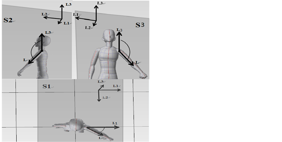
Figure 5. Definition of shoulder angle.
3.2. Kalman Filtering Tracking Algorithm for Feature Points
In the 1960s, Kalman published a famous paper on the recursive algorithm of linear filtering for discrete systems [5]. In the past decades, with the rapid development of the computer technology, Kalman filtering has been widely used in tracking, navigation, signal processing and the field of automatic control and derived a lot of improved algorithm [6]-[8].
In this system, the state vectors of the 14 feature points, (x, y, z) and , indicate three dimensional coordinates and speed in space,
  is the measurement vector [9]. The mathematical model established by Kalman filter is as follows:
State equation: (4)
(4)
Measurement equation: (5)
(5)
In the Equation (5), when the moment is k, X(k) is the state of the system, U(k) is the controlled variable (the controlled variable is 0 in the system), A is the state transition matrix, B is the system parameters of controlled variable and W(k) is the system process noise. In the Formula (6), when the moment is k, Z(k) is measurement value, H is the measurement matrix and V(k) is the system measurement noise. It is assumed that the process noise is not correlated with the measurement noise and satisfied with white noise which has normal distribution.
 (6)
(6)
In the system:
 (7)
(7)
 (8)
(8)
In the Equation (8),  is the sampling interval from k − 1 to k. The frame of the capture motion camera is 60,
 .
.
The image sequence is continuous and the motion capture cameras have higher sampling rate, the distance of feature points is small and continuous in adjacent frames, hence the feature points can be approximately regarded to have uniform motion. Consequently, the state equation and measurement equation of the system are expressed as the Equations (10) and (11).
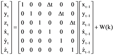 (9)
(9)
 (10)
(10)
Kalman filtering is a prediction process, but also a feedback process. In the Kalman filtering, the state of the next moment is predicted by the state of the previous time and the measurement values of the time to update the parameters in the system. In a conclusion, Kalman filtering system can be divided into two steps: prediction and updating. The process of Kalman filtering can be described by the Equations (12) and (13).
 (11)
(11)
 (12)
(12)
Through these equations, the prediction state of the system can be obtained. The measured value of the system can be obtained by combining with the predicted state, with the predicted state and the measured value to update the Kalman filter system. The Equations (14), (15) and (16) are updating equations.
 (13)
(13)
The equation of Kalman Gain (Kg(k)):
 (14)
(14)
The covariance (P (k|k)) of K moment optimal state estimate:
 (15)
(15)
In the actual tracking process, there will be situations of lost identity and disorder. For this, the system is added to the algorithm of restricting feature points by geometric relation method. In the Figure 3, there are 14 feature points. The feature of the head is shown as the points 1 and 2, the shoulder is points 3 and 9, the arm is points 3, 4 and 5 (and also 9, 10 and 11), the leg is points 7 and 13 (and also 13 and 14).The relative position between them is relatively fixed in the motion capture process. The human model can be divided into three parts: the head, trunk and legs. If the point of the head (1 or 2) is lost, the relative position relationship of the other point of head could be used to calculate the lost point’s possible range. And these data is compared with the prediction result of Kalman filtering to obtain a value. If the value is less than a certain threshold, it can be considered that the predictions match the lost or occlusion point.
4. Experimental Results and Analysis
Based on OpenGL graphics library the human body, electrical equipment and operating environment model are established as shown in. In Figure 6, the cabinet is an equipment model of the electrical switchgear. And the ground marker is the safety walk path.
In this system, the software is designed by using the VS2013 and open source visual library, Open CV. Open CV has many image processing and computer vision algorithms, and provides normal Kalman tracking algorithm function.
The function uses the 14 feature points’ data of a process by a trainee walking in the operating scene. The data includes a total of 500 frames. And the sampling interval is  s. The system noise and measurement noise is
white noise with the variance Q = 1.5 and R = 0.1. As shown in Figure 7 and Figure 8 the tracking results are effective.
From Tables 1-3, the average absolute error of coordinate tracking point is 1.61 mm and average relative error is 2.23%. The movement of the human body model has a relatively accurate tracking result.
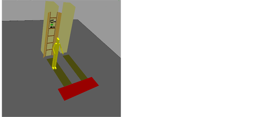
Figure 6. Panorama of models.
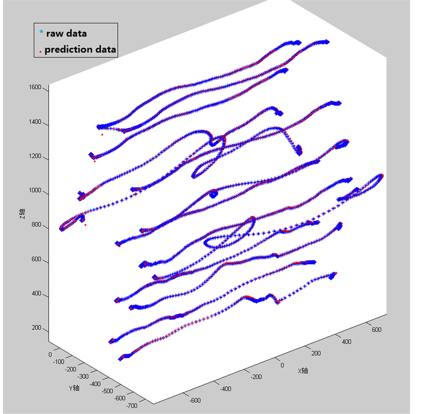
Figure 7. Results of tracking points.
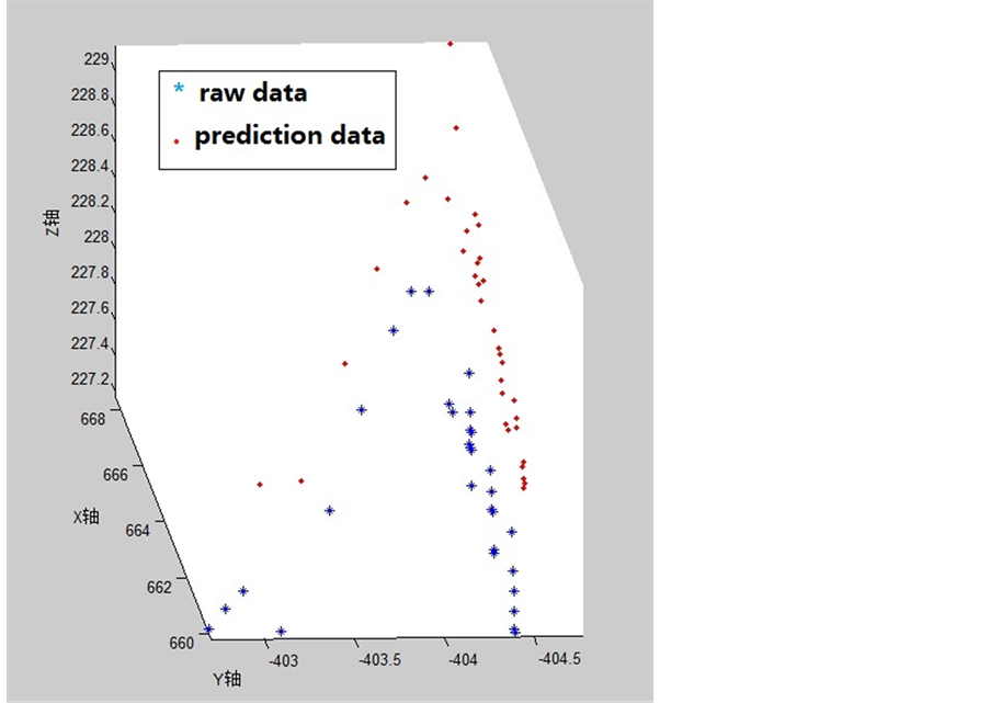
Figure 8. Results of characteristic point.

Table 1. Average relative error of tracking results.
Table 2. Maximum absolute error of tracking results.
Table 3. Average absolute error of tracking results.
5. Conclusion
According to the needs of the electric power enterprise’s development, an electricity safety entitative training system based on optical capture technology is designed in this paper. The constitution, the principle of the system, motion capture unit design and Kalman filtering algorithm are introduced. The experimental results show that the average absolute error of Kalman filtering algorithm capturing the three-dimensional coordinates of the feature points is 1.61 mm; the average absolute errors of X, Y, Z direction are respectively 3.08 mm, 0.85 mm, 0.89 mm; the average relative error is 2.23%, and the relative errors of the X, Y, Z direction are respectively 2.43%, 2.78%, 1.49%. Although the average absolute error and relative error is relatively high due to the fast- moving in the X direction, the result can basically meet the tracking requirements for the feature points.
Cite this paper
Huimeng Zhang,Lanxiang Wang,Shenghui Chu,Shuo Chen,Hao Meng,Guozhong Liu, (2016) Application of Optical Motion Capture Technology in Power Safety Entitative Simulation Training System. Optics and Photonics Journal,06,155-163. doi: 10.4236/opj.2016.68B026
References
- 1. Chen, J., Sun, F.L. and Lu, D. (1998) Review of Virtual Reality. Journal of Tianjin Polytechnic University, No. 2, 93-98.
- 2. Dyer, S., Martin, J. and Zulauf, J. (1995) Motion Capture White Paper. Technical Report, Silicon Graphics, 11-12.
- 3. Cui, J. (2008) The Creation of 3D Scene Based on Open GL. Beijing University of Chemical Technology.
- 4. Cui, B.Y. and Jin, Z.L. (2011) Statics Analysis and Structure Parameter Design of Robot Shoulder Joint Based on Orthogonal Mechanism. Optics and Precision Engineering, No. 1, 77-82.
- 5. Kalman, R.E. (1960) A New Approach to Linear Filtering and Prediction Problem. Transaction of the ASME—Journal of Basic Engineering, 35-45.
- 6. LeBreux, M., Désilets, M. and Lacroix, M. (2013) An Unscented Kalman Filter Inverse Heat Transfer Method for the Prediction of the Ledge Thickness inside high-Temperature Metallurgical Reactors. International Journal of Heat and Mass Transfer, 571.
- 7. Wang, X.C., Y.Z. and Zhao, K.C. (2013) Determination of Vision-Based Relative State by Modified Unscented Kalman Filter. Optics and Precision Engineering, No. 4, 1032-1039.
- 8. Gao, Z.M., Wang, S.Y., Zheng, Z.H. and Zheng, D.K. (2011) Improved Kalman Filter Algorithm for Maneuvering Target Tracking. Journal of Air Force Early Warning Academy, No. 5, 339-342, 346.
- 9. Zhao, Q.J., Tu, D.W., Gao, J. and Huang, Z.H. (2008) Kalman Filter Based Vision Predicting and Object Tracking Method and Its Application. Optics and Precision Engineering, No. 5, 937-942.
NOTES

*Corresponding authors.