Journal of Electromagnetic Analysis and Applications
Vol. 5 No. 5 (2013) , Article ID: 31747 , 6 pages DOI:10.4236/jemaa.2013.55036
Modal Resistance of Spiral Antenna
![]()
1Electromagnetics and Microwave Laboratory, Department of Electrical and Computer Engineering, Texas A&M University, College Station, USA; 2Fujitsu Laboratories of America, Inc., Sunnyvale, USA.
Email: tkchen@us.fujitsu.com, ghuff@tamu.edu
Copyright © 2013 Teng-Kai Chen, Gregory H. Huff. This is an open access article distributed under the Creative Commons Attribution License, which permits unrestricted use, distribution, and reproduction in any medium, provided the original work is properly cited.
Received November 26th, 2012; revised December 28th, 2012; accepted January 10th, 2013
Keywords: Spiral Antennas; Modal Resistance; Quasi-Static Analysis
ABSTRACT
This paper proposes a quasi-static conformal mapping analysis to analytically evaluate the input resistance of Archimedean spiral antenna at its radiation region. The deviation from the original constructs of band theory for two-wire spiral antennas leads to the concept of common slot-line mode radiation. The per-unit-length capacitance and the characteristic impedance of the quasi-TEM fundamental propagating mode in periodic coplanar waveguide (PCPW) structure are obtained in terms of spiral parameters including substrate properties. This formula enables little computational effort on the computation of input resistance at the radiation mode of balanced-excited two-arm Archimedean spiral antennas. The numerical simulation demonstrates the accuracy of derived formulas both in free space and when a dielectric layer is presented.
1. Introduction
The Archimedean spiral continues to be a widely studied antenna topology thanks to its broadband impedance and radiation characteristics. These have been investigated experimentally and computationally since their initial development in the late 1950s [1,2], and a number of numerical methods have been developed and utilized in the decades following their introduction to model these broadband attributes. Examples of this include the method of moments based on a thin-wire assumption [3,4], finite-volume time-domain (FVTD) [5], finite-difference time-domain (FDTD) [6,7], finite element method (FEM) [8,9], time-domain finite-element method (TDFEM) [10], and similarly constructed commercial full-wave solvers [11-14].
While these methods have no doubt been collectively successful in their own right, the pursuit of a physically descriptive and rigorous analytical analysis of the Archimedean spiral antenna has in many ways received less attention. This is especially true with regards to the input resistance of the structure. A semi-circular model was first proposed in 1960 [2] for this purpose, and the solution for an infinite number of equiangular spirals was obtained in 1961 [15]. Since then, the development of analytical solutions has seemingly been limited by the geometric complexity presented by the spiral antenna and the many variations it can embody.
It is commonly accepted that the basic operation of the Archimedean spiral can be accurately explained using band theory [1]. This theory states that for the two-wire spiral transmission line with negligible wire width the radiation occurs in annular regions where currents in the neighboring arms are in-phase. The lossy transmissionline model in [16] applies this concept using the radiation resistance of loop antennas as a means to capture the impedance behavior. By extending this explanation to include microstrip [17], stripline [11], and other printed antenna topologies where wire width can no longer be considered negligible, the current distribution will reside on the edge of the conductor and the power will radiated when the two neighboring current distributions are inphase. This leads to the concept of common slot-line mode radiation for the spiral antenna. When the common slotline mode radiation occurs, the field distribution and its structure are similar to the propagating coplanar waveguide mode, for which a closed-form analytical solution can be obtained using conformal mapping. The purpose of this work is to therefore provide physical insight into the radiation mechanism of the two-arm Archimedean spiral antenna and derive an efficient analytical solution for quick results in the design phase.
In this work, a conformal mapping approach is proposed to derive quasi-static closed-form solutions for the characteristic impedances of PCPW, which is used to characterize the input resistance of the balanced two-arm Archimedean spiral antenna operating in its radiation region. For completeness, the radiating mechanism of spiral antenna is reviewed first along with its geometry. This leads to the development of a model for the PCPW assuming the conductor is of negligible thickness. The mapping between physical and finite image domains is discussed next as a more straightforward approach towards deriving the input resistance of the spiral. A comparison is then made with full-wave electromagnetic solutions to validate the accuracy of this approach over a wide range of design parameters. A brief summary on the conformal mapping and resulting characterization of the spiral concludes the discussion.
2. Archimedean Spiral Antenna
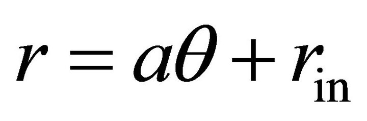
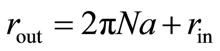
Figure 1 shows the two-arm planar gap-fed Archimedean spiral antenna considered in this work. It is center-fed with a tapered section based on the Dyson-style balun [18] to reduce the capacitive loading at the central feed location. The boundaries of the two metal arms are defined by four spiral curves using well-known Expression (1), where r is the radius of the spiral curve, θ is the winding angle in radians, 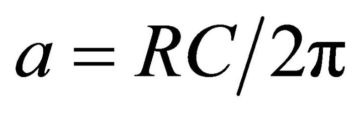 is the radius change rate of the spiral, RC is the radius change for one turn of a spiral arm, and rin is the inner radius of the spiral. The same values of a and rin are applied on these four curves, and the outer taper of the arm into a point is given by a circular curve defined using an offset angle θoff with the outer radius rout in (2) and N turns of the spiral.
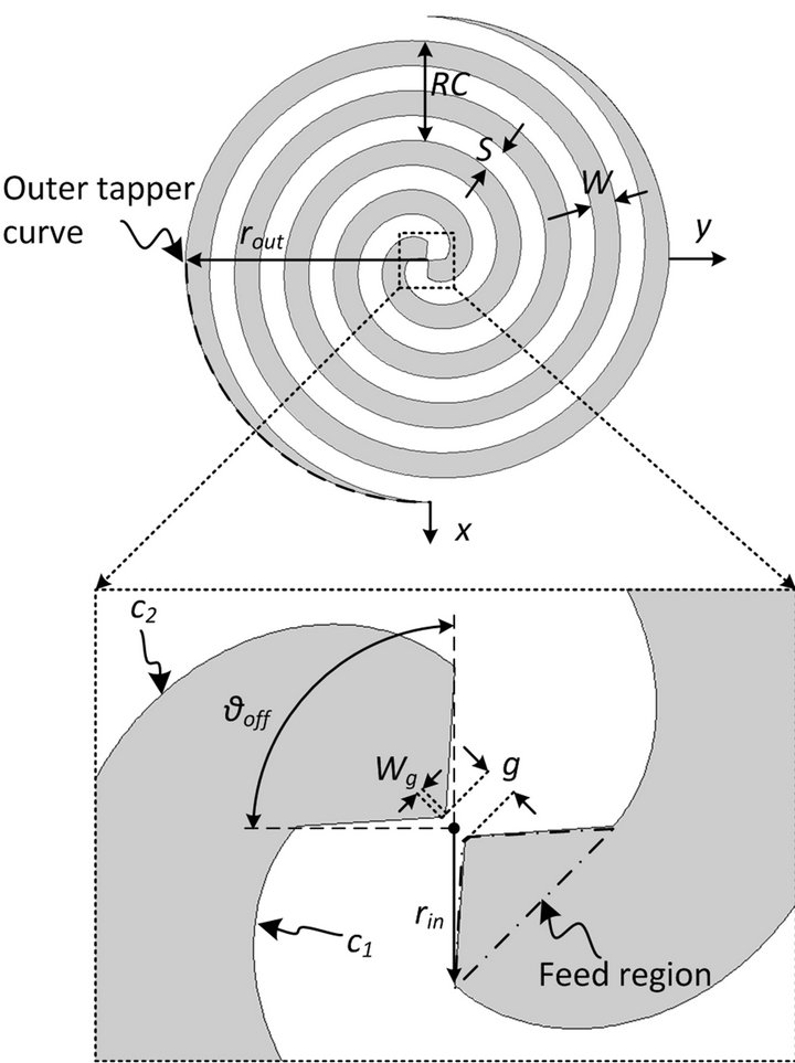
Figure 1. Layout of the two-arm gap-fed Archimedean spiral antenna in free space with non-negligible metal width and tapered-down arm terminations.
 (1)
(1)
 (2)
(2)
Using c1 and c2 to describe the two edge curves of one arm of the spiral requires  and
and  The width of the metal strip can then be defined as (3) and the resulting slot width can be obtained by noting that
 . The metallization ratio can then be defined by (4).
 (3)
(3)
 (4)
(4)
These parameters are well-defined in other works related to the spiral but they have been included here for continuity of nomenclature in later sections, to provide a quick reference for their physical meaning.
The feed region expanded in the bottom of Figure 1 has a gap length g with gap width Wg. More importantly, the design of this feed section remains critical to achieving the desired performance from the spiral antenna. It is discussed here since a simplified gap-fed excitation across g can provide an accurate prediction of radiation patterns (when compared to measured results), but discrepancies are often encountered when using this feed to predict the input resistance. This has historically been attributed to the presence of a feed cable and mutual coupling [19], which often shifts the measured impedance of the test antennas below the theoretically predicted impedance.
Hence, a theoretical self-complementary impedance can be obtained by numerical simulation (for example, in [19]) but difficulties are faced in measuring this same value—the experimental observations in [18,20] illustrate this shift. This suggests that the modeling of the feed structure must be included in the calculation in order to verify with the measured results for impedance [20], or careful consideration must be taken to minimize the capacitive loading it can create. In this work, the ratio of the gap width to gap length  is made as small as possible in an effort to reduce the gap capacitance and reduce its effect on the antenna’s impedance.
Although there is no rigorous mathematical description attached to the Band Theory, the theory states that for a two-wire spiral antenna with negligible wire-width, the radiation occurs in annular regions where currents in the neighboring arms are in-phase. The active region where this radiation occurs is similar to a loop antenna whose circumference on the spiral plane corresponds to one wavelength at the operating frequency f in (5), where rrad is the radius of the radiation region, λg is the guided wavelength propagating along the spiral arm, vp is the guided phase velocity, c is the speed of light, and εreff is the effective dielectric constant that the propagating wave experiences (if a dielectric substrate is present).
 (5)
(5)
3. Periodic Coplanar Waveguide Model
The Band Theory for two-wire spirals can be extended to include microstrip [17], stripline [11], and other printed antenna topologies where metal width can no longer be considered negligible. It is well-known that the current distribution resides on the edges of the metal strips in these transmission lines and a slot-line mode propagates between the arms. The spiral shape creates a path difference between the outer curve and inner curve of one spiral arm, so following the principles of the Band Theory, it can be deduced that the power radiates when the two neighboring current distributions on the same metal strip are in-phase. This is similar to common mode radiation. Figure 2 shows the cross-section of a nominal spiral (top) and the field distribution on these arms when the two neighboring currents on one spiral arm are in-phase (bottom).
Hence, when radiation occurs from the common slotline mode, both the field distribution and its physical structure are similar to the propagating TEM coplanar waveguide mode. With multiple turns, the interdigitated Arm 1 and Arm 2 shown in Figure 2 (bottom) appear as a periodic structure. This leads to the analysis of periodic coplanar waveguide (PCPW). Using the symmetry of the electric field distribution, a set of perfect electric conductor (PEC) walls and perfect magnetic conductor (PMC)
Figure 2. Cross-sectional view of a two-arm Archimedean spiral antenna along yz-plane (top) and the electric field distribution (bottom) when radiation occurs, which is similar to the coplanar waveguide mode but with periodicity along the spiral cross section (named periodic coplanar waveguide (PCPW) mode).
walls can be placed at the middle plane of the slot and the metal strip, respectively. The notional electric field distribution shown in Figure 2 is explicitly valid only for an infinite number of arms with equal current and field distributions. A similar distribution can be assumed for a finite number of arms over the frequencies where common mode radiation occurs.
3.1. Conformal Mapping Analysis in Free Space
The conformal mapping analysis is performed here to calculate the characteristic impedance of PCPW transmission line. The quasi-static assumption can provide an accurate prediction across a wide frequency band [21,22] where RF and microwave spiral antennas operate. The quasi-TEM wave propagation will be maintained by ensuring  for Archimedean spiral and PCPW. The metal strips have negligible thickness and are perfect electrical conductors. The per-unit-length (P.U.L.) capacitance C0 is the only unknown parameter required to obtain the quasi-static characteristics [23]. Conformal mapping techniques are used here since the potential functions and the capacitances between corresponding conductors are preserved after mapping to a simpler domain for which solutions are easily obtained. The general mapping processes used in this work can be found in [24,25]. The characteristic impedance Z0 of the propagating wave in PCPW when the two neighboring currents are in-phase can be obtained by (6), where ε0 is the permittivity in free space and
  is called a complete elliptic integral of first kind with the modulus k0 expressed in (7).
 (6)
(6)
 (7)
(7)
3.2. Conformal Mapping Analysis in a Dielectric Slab
The spiral antenna embedded in a dielectric slab is examined because of the author’s previous research on stripline-fed Archimedean spiral antennas [11]. For the sake of clarity, a single-layered substrate-embedded PCPW is sufficient to explain conformal mapping steps, while the theory presented below is applicable to the general case of multilayered structures or PCPW on top of substrates. Note that the CPW have less field overlap with surface wave modes at low frequencies where the phase velocity of the surface wave mode is much higher than the CPW mode [26].
Figure 3 shows the cross sectional view of spiral antenna embedded in a dielectric slab with thickness of 2h and dielectric constant of εr. The total P.U.L. capacitance C of substrate-embedded PCPW can be evaluated by the partial capacitance approximation [27] and modeling the air-dielectric interface as a PMC. The accuracy of this approximation [28] is limited to εr being greater than that of background medium. The P.U.L. capacitance C1 can then be obtained using (8) and the modulus in (9), where  is the Jacobian elliptic function with a variable z and a modulus k.
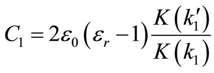 (8)
(8)
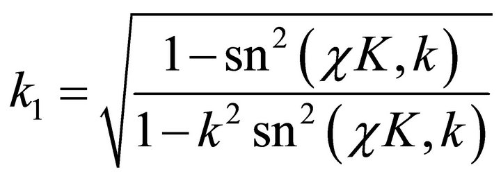 (9)
(9)
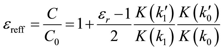
The effective dielectric constant εreff and the characteristic impedance Z0 for the quasi-TEM propagating mode in PCPW can then be derived in (10) and (11), respectively.
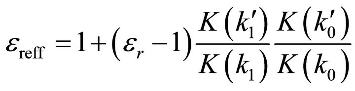 (10)
(10)
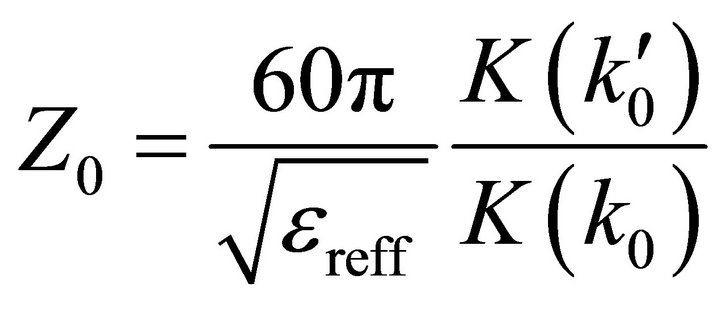 (11)
(11)
4. Measurement and Discussion
The two-arm gap-fed Archimedean spiral antenna in Figure 4 was fabricated and measured for further verification of the PCPW model and conformal mapping results. The prototype antenna has metallization ratio of  with the radius change of RC = 35 mm per turn. The outer radius of spiral is 75.9 mm and consists of two turns. The antenna was fabricated on a square
  substrate with
  and a thickness of h = 1.5748 mm [29]. The backside of fabriccated antenna has no conductor plane. The infinite balun design proposed in [18] is adopted as a feed, which requires a large metal arm to carry the feeding cable with less impact on antenna properties. The dummy cable on the other arm is necessary to remain the symmetry of spiral structure, as shown in Figure 4. The length of coaxial cable is 914.4 mm for de-embedding the measured point to the input terminal of spiral antenna.
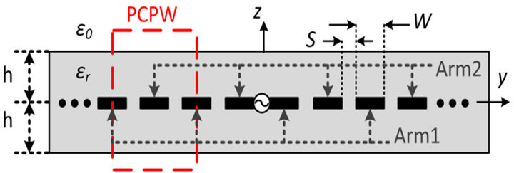
Figure 3. Cross sectional view of a two-arm Archimedean spiral antenna embedded in a dielectric slab.
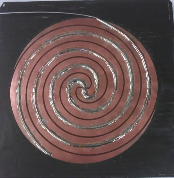
Figure 4. Fabricated prototype antenna without back conductor plane.
The conformal mapping analysis presented in previous section can be easily extended to the case of spiral antenna on the top of substrate, whose P.U.L. capacitance C1 becomes half of (8) and effective dielectric constant is
 (12)
(12)
The characteristic impedance of spiral antenna can be obtained by substituting (12) into (11). The calculated impedance for the fabricated antenna is 75.7854 Ω.
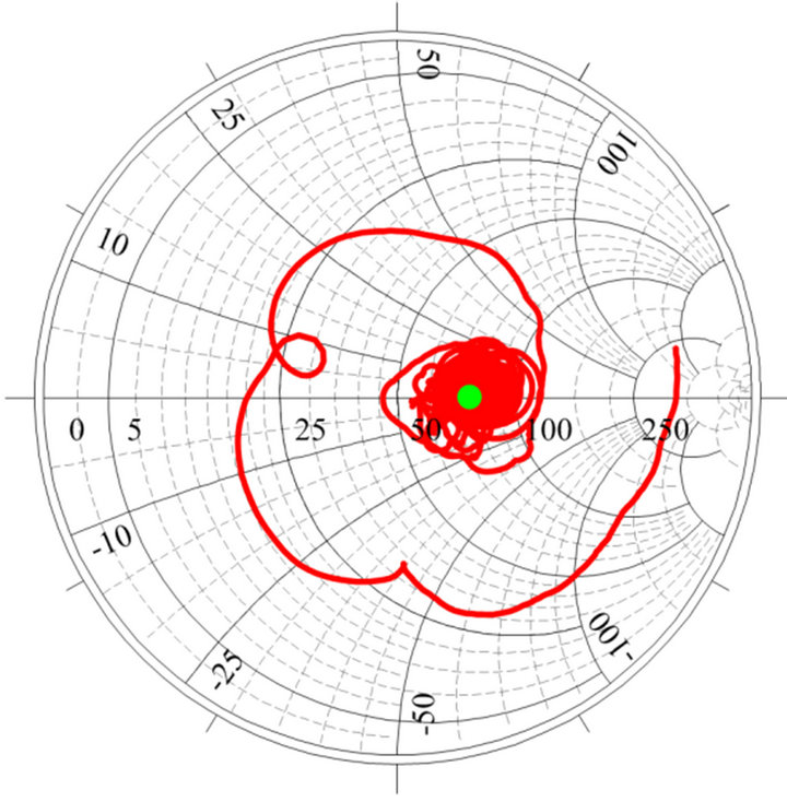
Figure 5 shows the measured and simulated impedances from 500 MHz to 8 GHz, both of which are around the calculated impedance of 75.7854 Ω (green point) above 1 GHz. The average measured and simulated impedances from 1 GHz to 8 GHz are 74.707 Ω and 72.157 Ω, respectively. As expected, the deviation of impedance curve is attributed primarily to the differences between the ideal model of spiral antenna and fabrication of the prototype (soldering of cables, adhesion of tape to foam, ragged surface of copper, and etc.). The experimental result is however in reasonable good agreement with the calculated results.
5. Conclusion
A simple model and analytical closed-form expressions for the modal resistance of an Archimedean spiral antenna have been obtained. This is the first time that quasi-static analysis is performed on spiral antenna to predict its input resistance operating in its radiation region, allowing physical insight when the spiral arm width
 (a)
(a)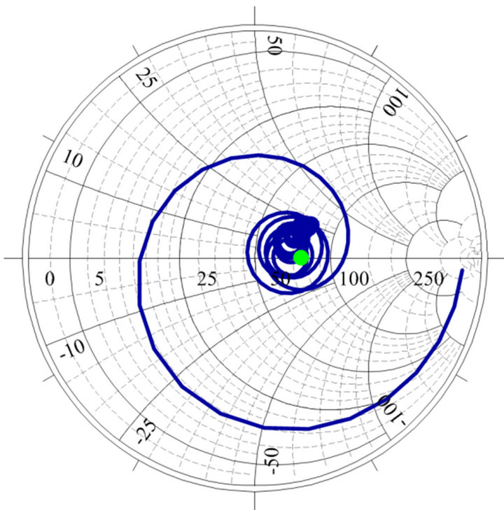 (b)
(b)
Figure 5. Measured input impedance (red line) after deembedded calibration of cable and simulated input impedance without infinite balun (blue line), where the green point shows the conformal mapping result of the spiral antenna.
is non-negligible and non-self-complementary. These expressions provide an accurate prediction for the impedance in free space or the band-average impedance with present substrates. The accuracy of the expressions has been verified by measurement and numerical simulation.
REFERENCES
- J. Kaiser, “The Archimedean Two-Wire Spiral Antenna,” IRE Transactions on Antennas and Propagation, Vol. 8, No. 3, 1960, pp. 312-323. doi:10.1109/TAP.1960.1144840
- W. Curtis, “Spiral Antennas,” IRE Transactions on Antennas and Propagation, Vol. 8, No. 3, 1960, pp. 298- 306. doi:10.1109/TAP.1960.1144850
- H. Nakano, “Helical and Spiral Antennas: A Numerical Approach,” John Wiley & Sons, New York, 1987.
- H. Nakano, K. Hirose, I. Ohshima and J. Yamauchi, “An integral Equation and Its Application to Spiral Antennas on Semi-Infinite Dielectric Materials,” IEEE Transactions on Antennas Propagation, Vol. 46, No. 2, 1998, pp. 267-274. doi:10.1109/8.660972
- C. Fumeaux, D. Baumann and R. Vahldieck, “FiniteVolume Time-Domain Analysis of a Cavity-Backed Archimedean Spiral Antenna,” IEEE Transactions on Antennas Propagation, Vol. 54, No. 3, 2006, pp. 844- 851. doi:10.1109/TAP.2006.869935
- C. W. Penney and R. J. Luebbers, “Input Impedance, Radiation Pattern, and Radar Cross Section of Spiral Antennas Using FDTD,” IEEE Transactions on Antennas Propagation, Vol. 42, No. 9, 1994, pp. 1328-1332. doi:10.1109/8.318663
- H. Nakano, H. Yasui and J. Yamauchi, “Numerical Analysis of Two-Arm Spiral Antennas Printed on a Finite-Size Dielectric Substrate,” IEEE Transactions on Antennas Propagation, Vol. 50, No. 3, 2002, pp. 362- 370. doi:10.1109/8.999628
- R. Li and G. Ni, “Numerical Analysis of 4-Arm Archimedian Printed Spiral Antenna,” IEEE Transactions on Magnetics, Vol. 33, No. 2, 1997, pp. 1512-1515. doi:10.1109/20.582548
- T. Ozdemir, J. L. Volakis and M. W. Nurnberger, “Analysis of Thin Multioctave Cavity-Backed Slot Spiral Antennas,” IEE Prodeedings H Microwaves, Antennas and Propagation, Vol. 146, No. 6, 1999, pp. 447-454.
- L. Zheng and J.-M. Jin, “Modeling and Simulation of Broad-Band Antennas Using the Time-Domain Finite Element Method,” IEEE Transactions on Antennas Propagation, Vol. 53, No. 12, 2005, pp. 4099-4110. doi:10.1109/TAP.2005.859905
- T.-K. Chen and G. H. Huff, “Stripline-Fed Archimedean Spiral Antenna,” IEEE Antennas Wireless Propagation Letters, Vol. 10, 2011, pp. 346-349. doi:10.1109/LAWP.2011.2141971
- D. J. Muller and K. Sarabandi, “Design and Analysis of a 3-Arm Spiral Antenna,” IEEE Transactions on Antennas Propagation, Vol. 55, No. 2, 2007, pp. 258-266. doi:10.1109/TAP.2006.889798
- C. Liu, Y. Lu, C. Du, J. Cui and X. Shen, “The Broadband Spiral Antenna Design Based on Hybrid BackedCavity,” IEEE Transactions on Antennas Propagation, Vol. 58, No. 6, 2010, pp. 1876-1882. doi:10.1109/TAP.2010.2041147
- M. N. Afsar, W. Yong and R. Cheung, “Analysis and Measurement of a Broadband Spiral Antenna,” IEEE Antennas Propagation Magazine, Vol. 46, No. 1, 2004, pp. 59-64. doi:10.1109/MAP.2004.1296145
- B. Cheo, V. Rumsey and W. Welch, “A Solution to the Frequency-Independent Antenna Problem,” IRE Transactions on Antennas Propagation, Vol. 9, No. 6, 1961, pp. 527-534. doi:10.1109/TAP.1961.1145057
- M. Lee, B. A. Kramer, C.-C. Chen and J. L. Volakis, “Distributed Lumped Loads and Lossy Transmission Line Model for Wideband Spiral Antenna Miniaturization and Characterization,” IEEE Transactions on Antennas Propagation, Vol. 55, No. 10, 2007, pp. 2671-2678. doi:10.1109/TAP.2007.905823
- M. Kim, H. Choo and I. Park, “Two-Arm Microstrip Spiral Antenna for Multi-Beam Pattern Control,” Electronics Letters, Vol. 41, No. 11, 2005, pp. 627-629. doi:10.1049/el:20051110
- J. Dyson, “The Equiangular Spiral Antenna,” IRE Transactions on Antennas Propagation, Vol. 7, No. 2, 1959, pp. 181-187. doi:10.1109/TAP.1959.1144653
- Z. Lou and J.-M. Jin, “Modeling and Simulation of Broad-Band Antennas Using the Time-Domain Finite Element Method,” IEEE Transactions on Antennas Propagation, Vol. 53, No. 12, 2005, pp. 4099-4110. doi:10.1109/TAP.2005.859905
- M. McFadden and W. R. Scott, “Analysis of the Equiangular Spiral Antenna on a Dielectric Substrate,” IEEE Transactions on Antennas Propagation, Vol. 55, No. 11, 2007, pp. 3163-3171. doi:10.1109/TAP.2007.908838
- S. S. Bedair and I. Wolff, “Fast, Accurate and Simple Approximate Analytic Formulas for Calculating the Parameters of Supported Coplanar Waveguides for (M)MIC’s,” IEEE Transactions on Microwave Theory and Techniques, Vol. 40, No. 1, 1992, pp. 41-48. doi:10.1109/22.108321
- G. Ghione and C. U. Naldi, “Coplanar Waveguides for MMIC Applications: Effect of Upper Shielding, Conductor Backing, Finite-Extent Ground Planes, and Line-toLine Coupling,” IEEE Transactions on Microwave Theory and Techniques, Vol. 35, No. 3, 1987, pp. 260-267. doi:10.1109/TMTT.1987.1133637
- R. E. Collin, “Foundations for Microwave Engineering,” 2nd Edition, Wiley-IEEE Press, New York, 2000.
- T. A. Driscoll and L. N. Trefethen, “Schwarz-Christoffel Mapping,” Cambridge University Press, Cambridge, 2002. doi:10.1017/CBO9780511546808
- I. S. Gradshteĭn and I. M. Ryzhik, “Table of Integrals, Series and Products,” 7th Edition, Academic Press, Oxford, 2007.
- M. Riaziat, R. Majidi-Ahy and I. J. Feng, “Propagation Modes and Dispersion Characteristics of Coplanar Waveguides,” IEEE Transactions on Microwave Theory and Techniques, Vol. 38, No. 3, 1990, pp. 245-251. doi:10.1109/22.45333
- C. Erli and S. Y. Chou, “Characteristics of Coplanar Transmission Lines on Multilayer Substrates: Modeling and Experiments,” IEEE Transactions on Microwave Theory and Techniques, Vol. 45, No. 6, 1997, pp. 939- 945. doi:10.1109/22.588606
- G. Ghione and M. Goano, “Revisiting the Partial-Capacitance Approach to the Analysis of Coplanar Transmission Lines on Multilayered Substrates,” IEEE Transactions on Microwave Theory and Techniques, Vol. 51, No. 9, 2003, pp. 2007-2014. doi:10.1109/TMTT.2003.815873
- RT/Duroid® Laminates: Rogers Corporation, Rogers, CT.