Journal of Electromagnetic Analysis and Applications
Vol. 3 No. 9 (2011) , Article ID: 7465 , 7 pages DOI:10.4236/jemaa.2011.39061
Novel Globular Magnetic Actuator Group Capable of Free Movement in a Complex Pipe
![]()
Faculty of Engineering, Tohoku Gakuin University, Tagajo, Japan.
E-mail: yaguchi@tjcc.tohoku-gakuin.ac.jp
Received July 11th, 2011; revised August 10th, 2011; accepted August 21st, 2011.
Keywords: Magnetic Actuator Group, Globular Type, Magnetic Connection, Reversible Motion, Shape-Memory-Alloy
ABSTRACT
Finding damage inside pipes is important for the inspection of complex pipes used in nuclear power plants and chemical plants. A number of studies have investigated the mechanisms of an actuator with an electric cable to provide locomotion through various devices in complex pipes. An in-pipe robot capable of movement in narrow complex pipes has not yet been developed. In the present paper, we propose a globular magnetic actuator group that exhibits a very high thrust force and is capable of free reversible motion in complex pipes. Two actuators of the same size and characteristics are coupled by the magnetic connection method, which generates almost no mechanical loss. The globular magnetic actuator group capable of reversible motion through elongation and contraction of eight shape-memory-alloy (SMA) coils was fabricated. Experimental results indicate that the prototype actuator group is able to climb at a rate of 29 mm/s in a straight pipe while pulling a load mass of 48 g. In addition, the average speeds for two patterns of movement in a complex pipe with several curved sections and step sections were measured. The prototype actuator group is able to move in a complex pipe at an average speed of over 30 mm/s. This actuator group has several possible applications, including inspection using a micro-camera and pipe maintenance.
1. Introduction
In order to quickly find damage to chemical plants, nuclear reactors, and other such installations, an actuator capable of free movement in a complex pipe is required. Safety issues have encouraged the use of such actuators in recent years for a variety of tasks, including inspection, maintenance, and cleaning. On the other hand, there is increasing demand for in-piping actuators, which can be used to insert electrical wires into the complex pipe structure of newly constructed buildings. Several studies have investigated possible mechanisms for movement within pipes [1-7].
However, a freely movable actuator in a complex pipe of small inner diameter with several curved sections and step sections has not yet been investigated. As such, the authors proposed [8] a new globular magnetic actuator that is capable of free movement in a complex pipe having an inner diameter of 25 mm. There are potential problems in the design of the actuator, and it is necessary to increase the propulsion force of the total system in order to install additional components, such as a micro-camera and a transmitter. The propulsion force of the total system is expected to be doubled by connecting two actuators having the same characteristics.
The present paper proposes a globular magnetic actuator group that is capable of free reversible movement in a complex pipe. Two actuators of the same size and characteristics were coupled by the magnetic connection method, which generates almost no mechanical loss. Furthermore, we introduce reversible motion of the globular magnetic actuator group through on-off control of the input current in eight shape-memory-alloy (SMA) coils.
Experimental results reveal that the propulsion force of the two actuators is twice that compared of a single actuator. The possibility of increasing the propulsion force of the total system N times by connecting N single actuators is then demonstrated. In addition, this actuator group is able to move freely in a complex pipe with several curved sections and step sections.
The results indicate the feasibility of the realization of a highly mobile actuator group capable of reversible movement in complex pipes of small diameter.
2. Globular Magnetic Actuator Group Capable of Free Reversible Movement in a Complex Pipe
Figure 1 shows globular magnetic actuators A and B, which have the same size and characteristics. The actuators are combined using the magnetic connection method. Each actuator is composed of a hollow acrylic ball in diameter 20 mm with a groove, a propulsion module inserted in the acrylic ball, the four shape-memory-alloy (SMA) coils A, B, C and D, two caps attached at tips of the acrylic balls, two-layer compound materials A and B, four copper conductors attached to the compound material, and an acrylic pole as shown Figure 2. The SMA coil is in the shape of a spring with an outer diameter of 0.4 mm and a length of 14 mm when the SMA coil is fully contracted. The outer diameter of the SMA wire used to form the SMA coil is 0.15 mm. This SMA coil has an electrical resistance of 400 Ω per unit length. Accordingly, the electrical resistance of this SMA coil is 5.6
Ω. The compound material used to support the actuator group in the pipe is composed of a natural rubber and a thin plastic sheet. The compound material has a length of 40 mm and a width of 7 mm. The thickness of the rubber is 1.2 mm, and the thickness of the plastic sheet is 0.2 mm.
The propulsion module of each actuator consists of two identical permanent magnets, two acrylic pipes, a translational spring, and an electromagnet, as shown in Figure 1. A permanent magnet was attached to an acrylic pipe having an outer diameter of 8 mm, and the acrylic pipe was attached to the acrylic ball. A mass-spring system composed of the electromagnet and the translational spring was inserted into the acrylic ball. The translational spring is constructed of stainless steel and has an outer diameter of 7 mm, a free length of 12 mm, and a spring constant of k = 880 N/m. The permanent magnet is a cylindrical NdFeB magnet and is magnetized in the axial direction. The magnet is 7 mm in diameter and 3 mm in

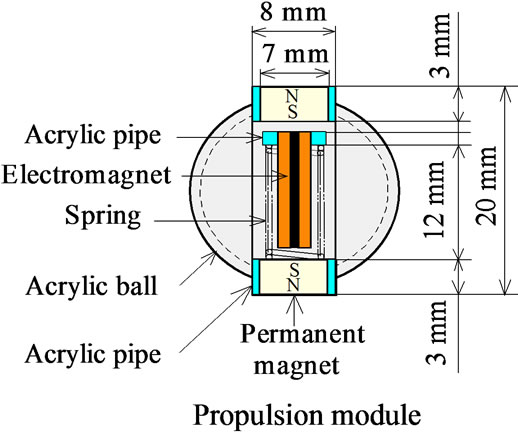
Figure 1. Two globular magnetic actuators having the same shape and characteristics.
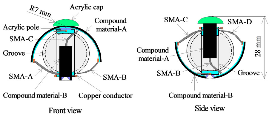
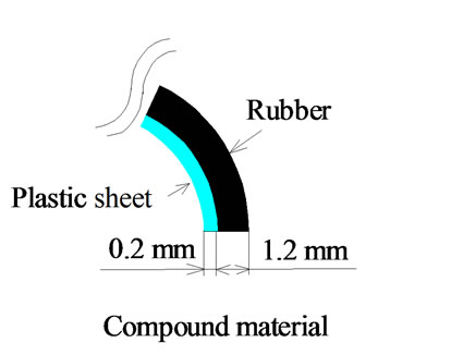

Figure 2. Structure of globular magnetic actuator-A.
height. The surface magnetic flux density as measured by a teslameter is 345 mT. The electromagnet consists of an iron core of 2.2 mm in diameter with 350 turns of 0.14 mm diameter copper wire. The electrical resistance of the electromagnet is 5 W. The gap between the iron core and the permanent magnet in the static condition is 2 mm. The total mass of the globular magnetic actuator group is 18 g.
The two actuators were coupled by the magnetic connection method, as shown in Figures 1 and 3. The magnetic connection component is composed of a steel rod with an outer diameter of 1.7 mm and a length of 7.6 mm, and two plastic circular plates with an outer diameter of 7 mm and a thickness of 0.8 mm. This circular plate has a hole with a groove to connect electrical wires. The magnetic connection rod and the permanent magnets attached to both edges of the individual actuator are combined magnetically. The constraint force due to this method is a very strong in the longitudinal direction and has very weak in the lateral direction, as shown in Figure 3. For this magnetic connection, the constraint force in the longitudinal direction is 0.98 N. On the other hand, the connection of the two actuators is easily canceled by a force of 0.03 N acting at the tip of a steel rod.
3. Principle of Locomotion
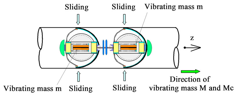
We think that the actuator group moves by using the inertia force of each vibrating mass, m. The principle of locomotion is as follows.
1) As shown in Figure 4(a), the supporting force of the compound material is not changed due to the inertia force of a vibrating mass, m, when the vibrating mass, m, vibrates in the positive z direction. The actuator group is able to slide when the inertia force of the vibrating mass, m, is larger than the frictional force between the compound material and the wall of the pipe.
2) On the other hand, as shown in Figure 4(b), the tip of the compound material is locked to the inner wall of the pipe when the vibrating mass, m, moves in the negative z direction. In this case, the frictional force between the compound material and the wall of the pipe becomes quite large compared with the inertia force of the vibrating mass, m. Therefore, the actuator group is not able to move.
3) The frictional force between the compound material and the wall of the pipe inside alternately changes during one period of vibration. As a result, the actuator is able to move only in one direction of the z coordinate.
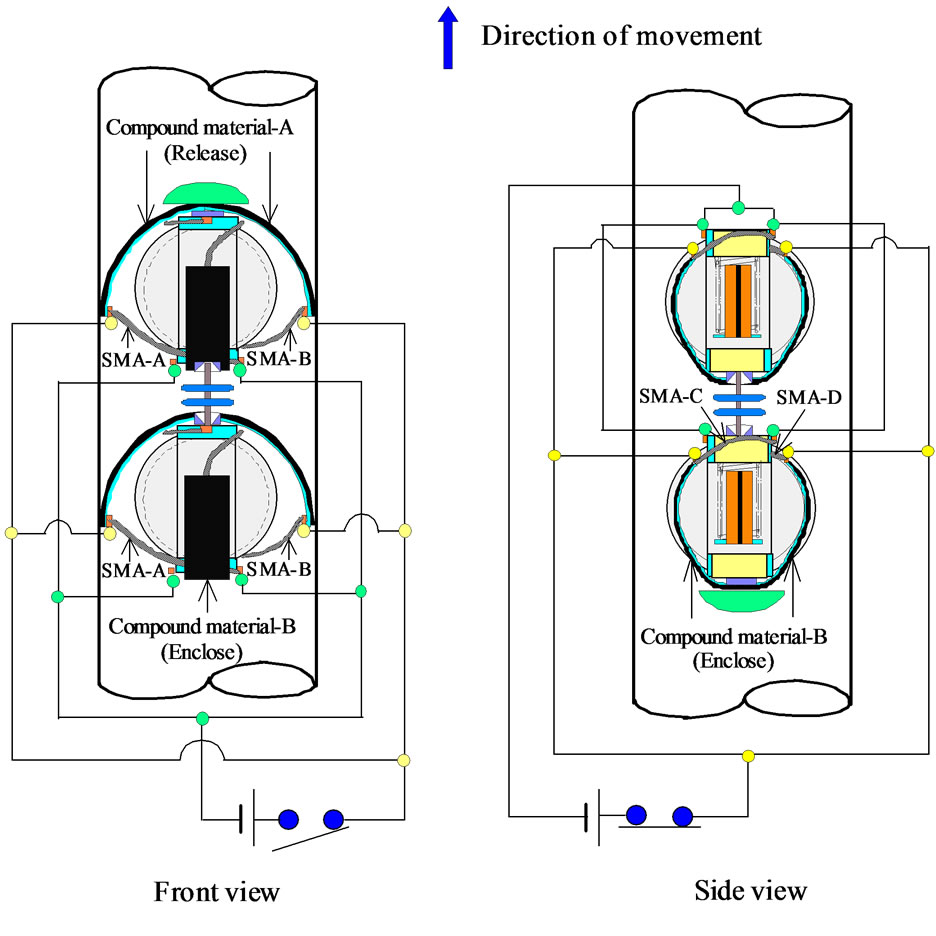
4. Principle of Reversible Motion
Figure 5 shows an outline of the reversible motion for the globular magnetic actuator group. The SMA coils are heated when the direct current is electrified by means of the SMA coils though connection with the DC power supply. Therefore, the SMA coils contract. The compound material B is completely enclosed due to contrac-
 (a)
(a)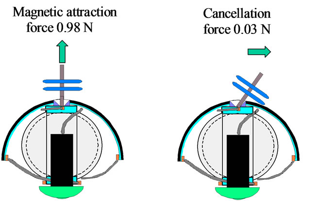 (b)
(b)
Figure 3. Schematic diagram of magnetic connection. (a) Actuator with magnetic connection; (b) expanded view of magnetic connection.
 (a)
(a)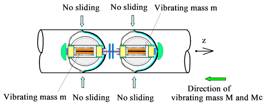 (b)
(b)
Figure 4. Principle of locomotion. (a) Movement case; (b) no-movement case.
 (a)
(a)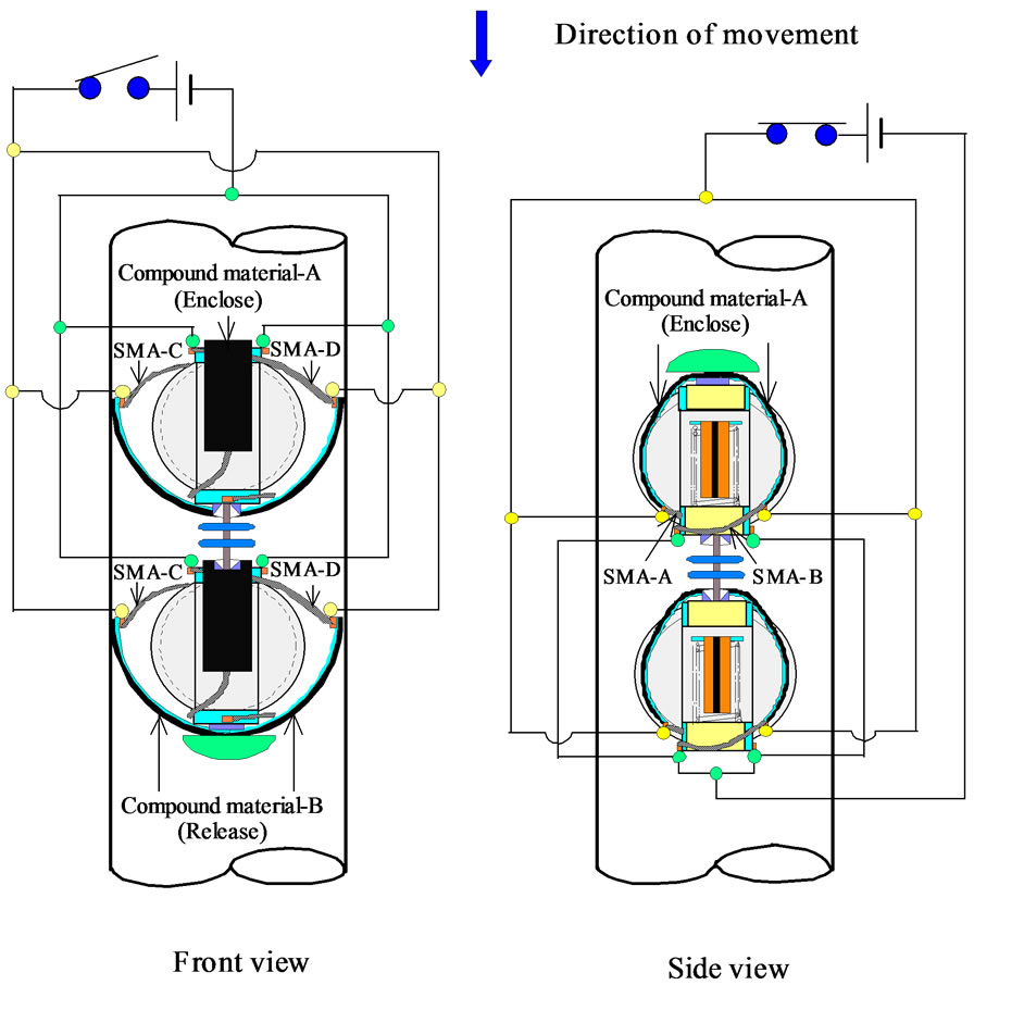 (b)
(b)
Figure 5. Method of reversible motion due to control of input current into SMA coils. (a) Straight upward; (b) straight downward.
tion of SMA coils C and D of the individual actuator when a direct current of 0.2 A is applied to SMA coils C and D. The generating force per SMA coil is 0.25 N. The globular magnetic actuator group is able to move straight upward, as shown in Figure 5(a).
On the other hand, the compound material A is completely enclosed when the direct current of 0.2 A is applied to SMA coils A and B of the individual actuator. SMA coils C and D are cooled by air-cooling when the supply of the direct current into SMA coils C and D is stopped. After a few seconds, the compound material B of the individual actuator is released by the elastic restoration force of the material itself. As a result, the globular magnetic actuator group is able to move straight downward in Figure 5(b). The acrylic ball has a groove of 8 mm in width and 2 mm in depth, because the compound material and inner wall of the pipe are not in contact when the compound material was completely enclosed.
The eight SMA coils were connected to the DC power supply, and the electromagnet was connected to an amplifier, as shown in Figure 6. Five electrical wires with outer diameters of 0.1 mm were used to control the movement direction of the globular magnetic actuator group.
5. Locomotion Characteristics of the Globular Magnetic Actuator Group
An experimental test was conducted using the apparatus shown in Figure 7. The resonance frequency of the magnetic actuator as measured by the experimental apparatus was 132 Hz. In the present paper, the effective value of an alternating current into the electromagnets of the actuator group is 0.4 A, unless otherwise noted.
The solid line in Figure 8 indicates the relationship between inner diameter of the straight pipe and the vertical upward speed of the globular magnetic actuator group capable of reversible motion for the case in which the width of the compound material was 7 mm. The broken line in Figure 8 indicates the results for the single actuator for the case in which the effective value of the alternating current into the electromagnet is 0.2 A. The moving characteristic of the globular magnetic actuator group indicates good performance over a wide range of inner diameters of from 23 mm to 30 mm. The measurement of the moving speed for the actuator was then carried out

Figure 6. Connection of eight SMA coils and electromagnet.
Figure 7. Experimental apparatus.
Figure 8. Relationship between inner diameter of straight pipe and vertical upward speed.
using the compound material with a width of 7 mm.
Figure 9 shows the relationship between the tilt angle α of the pipe, as shown in Figure 7, and the speed of the globular magnetic actuator group with respect to the straight pipe having an inner diameter of 23 mm, 25 mm, and 27 mm. The tilt angle α was varied from –90˚ (straight downward) to 90˚ (straight upward). The maximum vertical upward speed was 73 mm/s for the case in which the inner diameter of the pipe was 25 mm.
Figure 10 shows the relationship between the load mass and the vertical upward speed of the actuator group for a straight pipe having an inner diameter of 23 mm, 25 mm, and 27 mm. In this case, the mass was divided into two halves, which were applied to actuators A and B using two strings. This figure indicates that the globular magnetic actuator group was able to climb at a rate of 29 mm/s when pulling the load mass of 48 g through a pipe having an inner diameter of 25 mm, indicating moderately high performance. In this figure, the broken line shows the results of the single actuator for the case in which the effective value of the alternating current into the electromagnet is 0.2 A. The propulsion force of the two actuators is twice that of the single actuator. The propulsion force of the total system obtained by connecting an actuator constructed of N single actuators increases N times.

Figure 9. Relationship between tilt angle and speed.
Figure 10. Relationship between load mass and vertical upward speed.
6. Locomotion Characteristics of the Globular Magnetic Actuator Group in a Complex Pipe
Figure 11 shows a schematic diagram of a complex pipe with several curved sections and step sections of 1.5 mm in the pipe. In addition, the diameter of the curved section and the diameter of the entrance section are different. A complex pipe with such a configuration is often used as joints of water supplies, cooling pipes, and heat exchangers. This complex pipe was constructed by combining two polyvinyl chloride U-joint pipes. The measurement distance was set as 110 mm with the one curved section and the two straight sections.
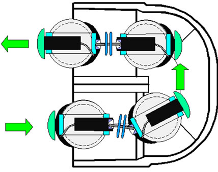
The average speed was measured for two patterns of movement in the horizontal direction, as shown in Figure 12. Compared to pattern I, in pattern II, the body of the globular magnetic actuator group in the pipe is rotated 90 degrees.
The experimental results show that, for both patterns, the average speed of the magnetic actuator group exceeds 30 mm/s by using the magnetic connection method demonstrated in this paper.
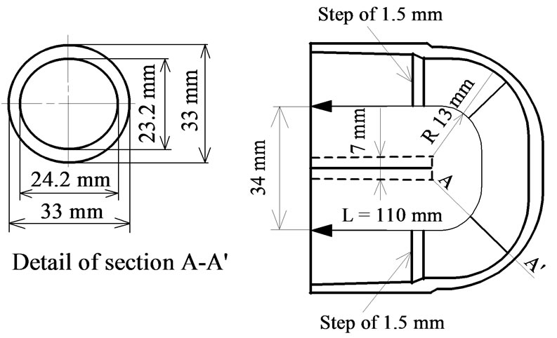
Figure 11. Schematic diagram of complex pipe.
 (a)
(a)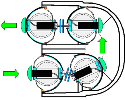 (b)
(b)
Figure 12. Two patterns of movement in complex pipe.
7. Conclusions
A globular magnetic actuator group capable of free movement in a complex pipe has been proposed and tested. In addition, we proposed a reversible motion of the globular magnetic actuator group due to on-off control of the input current into eight SMA coils. The experimental result indicates that the globular magnetic actuator group was able to climb at a rate of 29 mm/s when pulling a load mass of 48 g through a pipe having an inner diameter of 25 mm. The average speed was measured for two patterns of movement in a complex pipe. The results demonstrated that the globular magnetic actuator group was able to move in a complex pipe at an average speed of over 30 mm/s. The results of the present study demonstrated that the propulsion force of the total system of globular magnetic actuators can be increased N times by connecting N actuators. The propulsion force can be increased considerably by combining several actuators in series. In addition, the group of actuators can be easily driven using simple equipment, such as a generator and an amplifier. The proposed globular magnetic actuator system has several possible applications, including inspection using a micro-camera and pipe maintenance.
8. Acknowledgements
This work was supported in part by Grants-in-Aid for Scientific Research (C) (23560509), Japanese Ministry of Education (2011-2014).
REFERENCES
- Y. Kondo and S. Yokota, “Fluid Power Systems Involving the Use of an Electro-Rheological Fluid,” Transactions of the Japan Society of Mechanical Engineers, Vol. 64, No. 617, 1998, pp. 300-306.
- H. Saito, K. Sato, K. Kudo and K. Sato, “Fundamental Study of Mover Travel Inside a Small Diameter Pipe,” Transactions of the Japan Society of Mechanical Engineers, Vol. 66, No. 641, 2000, pp. 346-353.
- K. Suzumori, M. Takata and S. Wakimoto, “A Miniature Inspection Robot Negotiating Pipe of Widely Varying Diameter,” Journal of Robotics and Mechatoronics, Vol. 15, No. 5, 2003, pp. 555-560.
- Q. Pan and S. Guo, “A Paddling Type of Microrobot in Pipe,” Proceedings of IEEE International Conference on Robotics and Automation, Kobe, 12-17 May 2009, pp. 2995-3000.
- M. Ohno, T. Hamano and S. Kato, “Modeling and Fabrication of a Mobile Inspection Microrobot Driven by a Pneumatic Bellows Actuator for Long Pipes,” Journal of Robotics and Mechatoronics, Vol. 18, No. 1, 2006, pp. 11-17.
- M. Ohno, T. Hamano and S. Kato, “Modeling and Fabrication of a Mobile Inspection Microrobot Driven by a Pneumatic Bellows Actuator for Long Pipes,” International Journal of Advanced Robotic Systems, Vol. 7, No. 1, 2010, pp. 85-90.
- H. Yaguchi, K. Ishikawa and T. Zamma, “A Novel Cableless Magnetic Actuator Capable of Reversible Motion in a Thin Pipe,” IEEE Transactions on Magnetics, Vol. 45, No. 10, 2009, pp. 4530-4533. doi:10.1109/TMAG.2009.2021568
- H. Yaguchi and N. Sato, “Globular Magnetic Actuator Capable of Freely Movement in a Complex Pipe,” IEEE Transactions on Magnetics, Vol. 46, No. 6, 2010, pp. 1350-1355. doi:10.1109/TMAG.2010.2040712