Journal of Electromagnetic Analysis and Applications
Vol. 2 No. 4 (2010) , Article ID: 1682 , 6 pages DOI:10.4236/jemaa.2010.24034
Computation and Analysis of Propellant and Levitation Forces of a Maglev System Using FEM Coupled to External Circuit Model
![]()
College of Electrical Engineering, Zhejiang University, Hangzhou, China.
Email: shiyouyang@yahoo.com
Received December 31st, 2009; revised February 12th, 2010; accepted February 15th, 2010.
Keywords: Maglev System, Propellant Force, Levitation Force, Numerical Computation, Finite Element Method
ABSTRACT
This paper studies the propellant and levitation forces of a prototype maglev system where the propellant forces are provided by a linear motor system. For this purpose, the mathematical model and method using finite element method coupled to external circuit model is developed. The details of the propellant and levitation forces for a prototype maglev system under different operating conditions are investigated, and some directions are given for practical engineering applications.
1. Introduction
Due to the exclusive salient advantage of non-contact surfaces, an ever-increasing effort has been dedicated to the application of the magnetic levitation technology in engineering disciplines such as maglev trains [1], maglev carriers [2], maglev bearings [3], maglev vibration isolators [4], and so on. One of the key problems in the use of maglev technologies is the accurate and efficient determination of the propellant and levitation forces. Strictly speaking, the electromagnetic field of a maglev system is a complex three dimensional one involving movement components. To predict precisely the transient electromagnetic phenomena of this kind of problems, the complications such as the saturation of iron materials and the relative movement of the moving components must be taken into account properly. Moreover, in a maglev system, the electromagnetic phenomena are jointly generated by the propellant, the levitation and the guiding systems. Thus, one needs to consider all of these issues in the numerical simulations. In addition, the use of power electronic devices in the front end of the linear synchronous motor makes the situation even more serious since a voltage source must also be modeled. Therefore, one needs to resort to the numerical techniques of electromagnetic field computations.
Generally speaking, to address the aforementioned issues of the electromagnetic problem of a maglev system, it is essential to use three dimensional finite element methods [5]. However, the heavy computational burden for the implementation of 3D finite element method is numerically unaffordable for most application cases. In this point of view, the 2D time stepping finite element method [6] is proposed to couple to external circuit model to study the transient performances of a maglev system with the goal of developing an efficient and accurate numerical tool for the computations of the propellant and levitation forces of a maglev system.
2. Mathematical Models and Methods
2.1 Finite Element Model
The transient electromagnetic fields in the propellant and levitation systems are determined using 2D time-stepping finite element method. To determine the field distribution at each time step in a Maglev system, the 2D transverse section spanning one pole pitch of the linear synchronous motor is studied. As shown in Figure 1, the solution domain is comprised of the stator winding, the stator core, of the linear motor; the rotor core, and the winding of the levitation magnet/the rotor. With the displacement current being neglected, the field is governed by
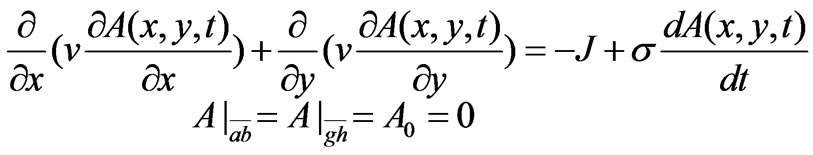 (1)
(1)
where, n is the reluctivity, s is the conductivity, J is the
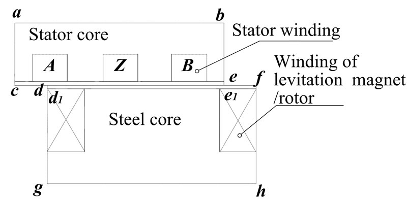
Figure 1. The Schematic diagram of the studied model
source current density, A(x,y,t) is the magnetic vector potential.
For a moving conductor with a velocity v, the induced electric density is
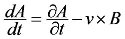 (2)
(2)
Using the Galerkin approach to discretize (1), one obtains
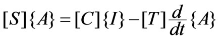 (3)
(3)
where,
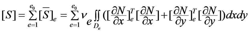 ,
,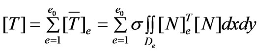 ,
,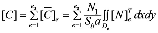 .
.
where, a is the number of the parallel branches of the winding, N1 is the number of total serial turns in one coil, Sb is the slot area, [N]e is the shape function of the finite element method.
2.2 External Circuit Models
In general, the source current density in (1) is unknown. Thus, the external electric circuit model is coupled to the finite element formulation in this paper to consider the voltage source. Moreover, the end effect of the propellant and levitation systems is also modeled in this circuit formulation. Figure 2 depicts schematically the equivalent circuit model of the winding of one phase. Mathematically, the external circuit model, including the electromotive force e, the leakage inductance Le, and resistance R of the windings, is
 (4)
(4)
where, [u] = [-uf ua ub uc ud]T, [I] = [if ia ib ic id]T, [R] = diag [rf ra rb rc rd], [Le] = diag [Lsf Lsa Lsb Lsc Lsd] is the leakage inductance considering the end effect of the machine and levitation magnet, subscript f denotes the winding of the levitation system/the rotor of the linear motor.
To express e in terms of A(x,y,t), one has
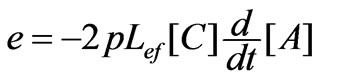 (5)
(5)
where Lef is the effective length of the core of the propellant and levitation systems.
2.3 Coupling of Finite Element and External Circuit Models
Integrating (3) and (5) as a whole, one reads
 (6)
(6)
2.4 Temporal Discretization
Applying Crank-Nicolson algorithm to (6) with respect to the time variable, one obtains the following equation set of the time-stepping finite element coupled to external circuit model
 (7)
(7)
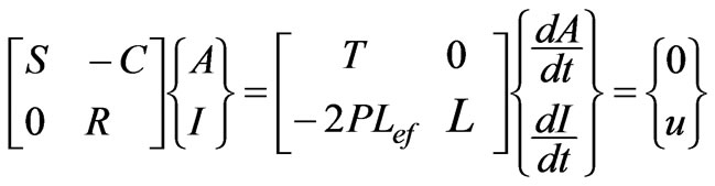
Rearranging (7) into a symmetric form, one has
 (8)
(8)
where,  , h is the size of the time step.
2.5 Treatment of the Relative Movement of Different Components in a Maglev System
To consider the relative movement of a maglev system, the moving boundary is used [7] in this paper. The moving

Figure 2. The equivalent circuit of one phase winding
boundaries are the boundaries connecting the stator and rotor meshes of the propellant system, and will vary with the movement. The nodes in the stator side and their counterparts in the rotor side satisfy either periodic or semi-periodic boundary conditions. For example, for a specific relative position of the stator and rotor as depicted in Figure 1, the moving boundary conditions are
 (9)
(9)
2.6 Numerical Computation of the Propellant and Levitation Forces
Once the electromagnetic field is determined in each time step, the corresponding propellant and levitation forces of the maglev system in that time instant can be determined from
 (10)
(10)
In the case study, fx is the propellant force, and fz the levitation force.
3. Numerical Results
To predict the transient performances of a maglev system, the computer codes using the proposed models and methods are developed by the authors. The codes are programmed in Fortran language.
3.1 Validation
To validate the proposed mathematical model and method as well as the computer codes, they are firstly used to compute the no-load propellant and levitation forces of a prototype Maglev train in Shanghai commercial Maglev Line. The mesh of total 4784 nodes and 9197 elements as shown in Figure 3 is used in this case study. The differences between the computed levitation and propellant forces and the exact ones for both forces are less than 5%. Obviously, this case study has positively confirmed the robustness and feasibility of the proposed model and method for solving the electromagnetic fields of a Maglev system problem.
3.2 The Study of Propellant and Levitation Forces of a Prototype Maglev System
After the accuracy and feasibility of the proposed model and method are confirmed, the transient performances of the propellant and levitation forces of a prototype Maglev system under different operating conditions are studied. Firstly, the effect of the torque angle of the linear motor on the propellant and levitation forces is investigated. As shown in Figure 4, the torque angle is defined as the angle

Figure 3. The meshes of one pole pitch region used for validations

Figure 4. The schematic diagram of the torque angle
in electrical degrees between the axes of the magnetic fields generated by the stator winding (windings A, Z, B in Figure 1) and by the rotor winding. The value of this angle will determine the initial relative position of the stator and rotor, i.e., the periodic and semi-periodic boundary conditions of Equation (9). Figures 5-7 show the computed transient propellant and levitation forces in cases of different torque angles, and Figure 8 depicts the relationship of the averaged propellant and levitation forces with torque angles. It is should be pointed out that

Figure 5. The transient propellant and levitation forces at d = 0°
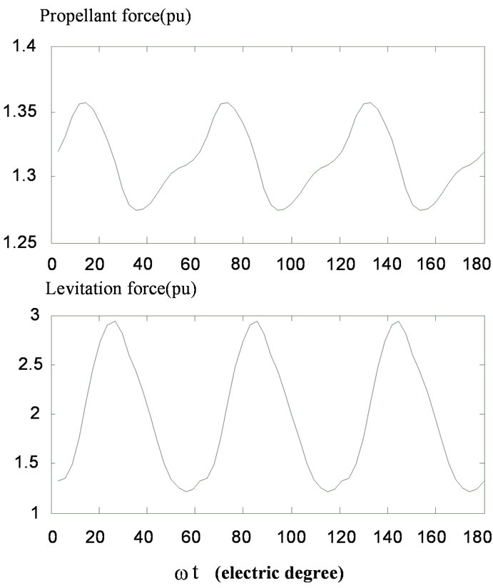
Figure 7. The transient propellant and levitation forces at d = 60°
the forces as given in these figures are normalized to their rated values. From these numerical results, it is obviously that 1) The torque angle of the linear motor has a significant effect on both the propellant and levitation forces;
2) The averaged propellant and levitation forces will change periodically with the torque angle.
Therefore, the running state of a Maglev system can be controlled by changing the torque angle of the linear motor.
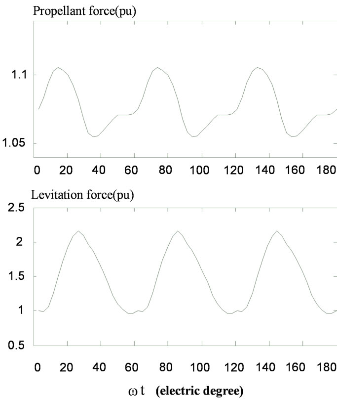
Figure 6 The transient propellant and levitation forces at d = 20°
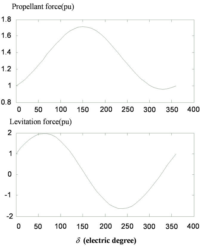
Figure 8. The averaged propellant and levitation forces under different power angle
Since the front end of the linear motor is generally a steady electronic device, typical a PWM source for high precise motion control, the high frequency harmonics are unavoidable in engineering applications of a Maglev system. In this regard, the effects of harmonics on the propellant and levitation forces are then studied using the proposed numerical model and method. In the computer simulation, the harmonic voltages are formulated as
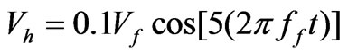 (11)
(11)
where Vf and ff are, respectively, the amplitude and frequency of the fundamental voltage of the source.
In the numerical implementation, the torque angle of the linear motor is set to different values. Figures 9 and 10 depict, respectively for torque angle d = 0° and d = 10°, the differences of the transient propellant and levitation forces of the prototype maglev system between the normal operating condition and the aggregation of harmonic voltages and currents. From these numerical results, it is clear that:
1) The averaged values of the differences of the transient propellant and levitation forces for one period will approach zero, this means that the harmonics of the sources have almost no effect on the steady state performances of the Maglev system;
2) In view of the transient propellant and levitation forces, the aggregation of harmonic voltages and currents will result in that the forces oscillate around their rated values, resulting in degradation in the transient performances of the Maglev system;
3) Relatively, the effect of a small harmonics on the levitation forces can be neglected compared to that on the
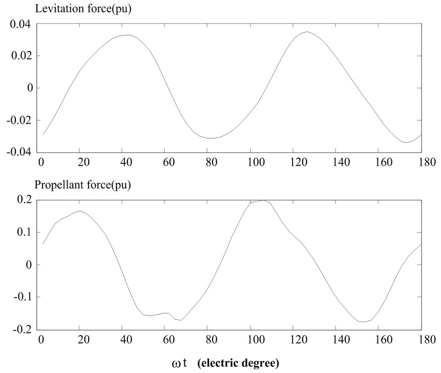
Figure 9. The differences of the transient propellant and levitation forces between the normal operating condition and the aggregation of harmonic voltages and currents at d = 0°
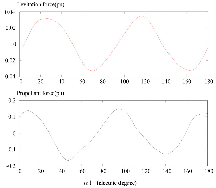
Figure 10. The differences of the transient propellant and levitation forces between the normal operating condition and the aggregation of harmonic voltages and currents at d=10°
propellant forces.
4. Conclusions
A model and method for computing the transient propellant and levitation forces of a Maglev system, with relative error being smaller than 5%, is proposed based on time stepping finite element method coupling to external circuit models. In addition to having the advantages to consider complications such as the relative movement of different components of the linear electrical machines, the saturation of iron materials, the proposed model and method can also take into account the interaction of an external voltage source which is very common with the increasing use of power electronics devices in the front end of general electromagnetic devices. Based on the computer simulation of this case study, for a maglev system, it is concluded that:
1) The torque angle of the linear motor has a significant effect on both the propellant and levitation forces;
2) The averaged propellant and levitation forces will change periodically with the torque angle;
3) The addition of small harmonics in the sources has almost no effect on the steady performances;
4) However, the aggregation of small harmonic voltages and currents in the sources will result in degradation in the transient performances.
5. Acknowledgements
This work is supported by the Science and Technology Department of Zhejiang Province under Grant No. 2008C31021.
REFERENCES
- Y. G. Guo, W. Xu, J. G. Zhu, H. Y. Lu and Y. Wang, “Design and Analysis of a Linear Induction Motor for a Prototype HTS Maglev Transportation System,” Proceedings of 2009 IEEE International Conference on Applied Superconductivity and Electromagnetic Devices, Chengdu, 25-27 September 2009, pp. 81-84.
- M. Morishita, T. Azukizawa, S. Kanda, N. Tamura and T. Yokoyama, “A New MAGLEV System for Magnetically Levitated Carrier System,” IEEE Transactions on Vehicular Technology, Vol. 38, No. 4, November 1989, pp. 230-236.
- Y.-M. Choi, M. G. Lee, D.-G. Gweon and J. Jeong, “A New Magnetic Bearing Using Halbach Magnet Arrays for a Magnetic Levitation Stage,” Review of Scientific Instruments, Vol. 80, No. 4, April 2009.
- K. Watanabe, S. Hara, Y. Kanemiteu, T. Haga, K. Yano, T. Mizuno and R. Katamura, “Combination of H∞ and PI Control for an Electromagnetically Levitated Vibration Isolation System,” Proceedings of the 35th Conference on Decision and Control, Kobe, 11-13 December 1996, pp. 1223-1228.
- M. Rizzo, A. Savini and J. Turowski, “3-D Finite Element Analysis of a Linear Reluctance Motor by Using Difference Scalar Potential, IEEE Transactions on Magnetics, Vol. 32, No. 3, May 1996, pp. 1533-1536.
- L. Y. Xu and W. N. Fu, “Evaluation of Third Harmonic Component Effects in Five-Phase Synchronous Reluctance Motor Drive Using Time Stepping Finite Element Method,” Proceedings of Industry Applications Conference, Rome, Vol. 1, 8-12 October 2000, pp. 531-538.
- R. Y. Tang, Y. Hu, Z. H. Lu, S. Y. Yang and L. J. Maio, “Computation of Transient Electromagnetic Torque in a Turbogenerator under the Cases of Different Sudden Short Circuits,” IEEE Transactions on Magnctics, Vol. 26, No. 2, March 1990, pp. 1042-1045.