Journal of Biomedical Science and Engineering
Vol.7 No.6(2014), Article ID:46024,12 pages DOI:10.4236/jbise.2014.76039
Chaos-Based Encryption of ECG Signals: Experimental Results
Gutenbert Kenfack, Alain Tiedeu
LETS, GRETMAT, National Advanced School of Engineering, University of Yaoundé I, Yaoundé, Cameroon
Email: kenfackwamba@yahoo.com, alain.tiedeu@gmail.com
Copyright © 2014 by authors and Scientific Research Publishing Inc.
This work is licensed under the Creative Commons Attribution International License (CC BY).
http://creativecommons.org/licenses/by/4.0/


Received 4 April 2014; revised 7 May 2014; accepted 14 May 2014
ABSTRACT
In this work, we suggest a system for chaos-based encryption of electrocardiographic signals. It uses simple electronics organized around a colpitts chaotic oscillator. The system has been designed, implemented and tested. The encrypted signal has been decrypted and compared to the original ECG signal. Experimental results were analysed and proved encouraging.
Keywords:ECG, Colpitts Oscillator, Chaos, Encryption, Decryption

1. Introduction
The need for ECG signal encryption cannot be overemphasized. In many countries, patient records often need to move from expert to expert on one hand. On the other hand, increasingly, portable ECG recorders allowing patients to make their own recording are used. These recordings are then regularly reported to a medical centre for analysis. Recently, in order to reduce the cost and to improve the service, electronic forms of medical records have been sent over networks from the laboratories to medical centres or to doctor’s offices. A form of remote assistance can thus be developed between countries with deficiency of specialists, including underdeveloped countries, and cardiology experts in the world. In all these cases, the ECG signal has to be encrypted to protect privacy.
Since the proof by Percorra et al. [1] of synchronization of chaotic oscillators, many researchers have devised and proposed diverse applications in secure communications. Basically, the works of the authors tackling this important problem in the literature can be roughly divided into two groups: the authors that use synchronization and those that do not use it. Just as its name implies, synchronization of chaos denotes a process in which two (or many) chaotic systems achieve a common dynamical behaviour after a transient duration. Here, the common behaviour may be a complete coincidence of the chaotic trajectories, or just a phase locking.
From the study by Kolumbàn et al. [2] , many notions of synchronization have been proposed for chaotic systems, the strongest and most widely-used of which is identical synchronization, where the state of the receiver system converges asymptotically to that of the transmitter [3] . More recently, two weaker notions of synchronization, called generalized synchronization [1] , [4] and phase synchronization [5] , [6] have been introduced.
The chaotic synchronization techniques which have been published to date are quite sensitive to both noise and distortion in the channel which makes signal recovery very difficult.
Mindful of the fact that synchronisation is very sensitive to noise, some authors have tried a number of techniques excluding any need for synchronization. The first of this type is chaos shift keying (CSK) [7] [8] . CSK is a method of digital modulation. Depending on the current value of the N-ary message symbol, the signal xi(t), (i = 1, ···N) from one of N chaos generators with different characteristics is transmitted. The main drawback of the CSK is that the threshold level required by the decision circuit depends on the signal to noise ratio (SNR). A special case of CSK is the chaotic on-off keying (COOK) [9] . COOK uses one chaotic oscillator, which is switched on or off according to a binary message symbol to be transmitted. The major disadvantage of the CSK system, namely that the threshold value of the decision circuit depends on the noise level, also appears in COOK. This means that by using COOK it is possible to maximize the distance between the elements of the signal set, but the threshold level required by the decision circuit depends on the SNR (Signal on Noise Ratio).
However, the threshold value can be kept constant and the distance can be doubled by applying the differential CSK (DCSK) [10] [11] . In DCSK, the two channels are formed by time division. For every message symbol, the reference signal is first transmitted, followed by the modulated reference carrying the message symbol. The principal drawback of DCSK arises from the fact that every information bit is transmitted by two sample functions because the bit rate is halved. In the literature, authors [12] [13] proposed frequency modulation DCSK (FM-DCSK) to tackle this problem. The peculiarity of this scheme is that the transmitted energy per bit belonging to one symbol, is kept constant. Both in the DCSK and FM-DCSK techniques, every information bit is transmitted by two sample functions, where the first part serves as a reference, while the second part carries the information. The modulator works in the same way as in DCSK, the only difference being that not the chaotic, but the FM modulated signal is the input of the DCSK modulator. The drawback of standard FM-DCSK system is the fact that only one information-bearing is transmitted after the reference signal.
Several different methods have been proposed in the literature to increase the data rate of DCSK, of which one of the most efficient is the quadratic chaos shift keying (QCSK) [14] [15] scheme. The basic idea underlying the QCSK scheme is the generation of chaotic signals which are orthogonal over a specified time interval. This allows the creation of a basis of chaotic functions from which arbitrary constellations of chaotic signals can be constructed. For instance, in QCSK, a linear combination of two chaotic basis functions is used to encode four symbols. The key point for exploiting this idea in a communication system is that one must be able to generate the chaotic basis functions starting from a single chaotic signal. The same concept holds for conventional digital communication schemes such as QPSK, where the quadrature component can be obtained from the phase one by means of a simple phase shifter. The main drawback of this method is its high complexity.
Among several systems proposed, one of the best performances has been achieved by the differential chaos shift keying (DCSK) scheme and its variation utilizing frequency modulation, and that is FM-DCSK.
Schemes based on the use of the chaos synchronization principle, all suffer from some common weakness [16] :
• It is difficult to determine the synchronization time; therefore, the message during the transient period will be lost.
• Noise throughout the transmission significantly affects the intended synchronization. This means the synchronization noise intensity should be small compared to the signal level, or the desired synchronization will not be achieved.
• Technically, it is difficult to implement two well-matched analog chaotic systems, which are required in synchronization, and if this is not required (i.e., with certain robustness) then the opponent can also easily achieve the same synchronization for attack.
A close look at the two groups of methods reveals some drawbacks. The main drawback of the first group of methods boils down to inaccuracy in synchronization. For the second group it is the fact that the decrypted signal is rather estimated which increases imprecision during recovery of the hidden signal.
In this work, we propose an encryption and decryption method for ECG signal, using simple electronics and whose principles and elements of novelty are described below. Our method is based on four important concepts that are encryption by adding the chaos to information to be hidden, multiplexing, demultiplexing and subtraction. In the literature, some authors have used methods of transmission to non-coherent receiver. We used this principle of non-coherent receiver. However, by multiplexing the signals, we use the same channel to carry the encrypted message and the reference signal. This differs from other non coherent receiver methods proposed in the literature where the coding of the information is done without putting itself on line as it is the case with coherent receiver systems. Our approach also differs from masking method encountered in coherent receiver system. Indeed, with such a system, encryption is also done by addition of course, but it requires the use of another chaotic oscillator at the reception and once synchronized, it serves as a reference for information retrieval. By carrying the reference signal, we bypass the stress of synchronization often difficult to perform when using another chaotic generator at the reception. The system is therefore free from the setbacks inherent to coherent system. Moreover, unlike in the other non-coherent systems presented in the literature where the recovered signal is only estimated, in our case, the decrypted ECG signal is deducted by the encrypted one. This adds to the accuracy of the proposed scheme. It should also be noted that the multiplexed signal is chaotic, composite and therefore cannot be synthesized by any pirate. This adds to the security.
In the next section, we shall describe the general organization of the system. Section III is devoted to experimental setting and result description followed by discussion of these results. This gives way to conclusion and a list of references.
2. Description of the EDS
The general organization of the Encryption-Decryption-System (EDS) is given in Figure 1. It is made of the ECG generator unit, an encryption unit and the decryption unit.
2.1. ECG Generator Unit
In this work, we used the ECG generator that was developed in our laboratory by Tchimnoue et al. [17] and that we succinctly described below. The generator is built around a 16F84A microcontroller (MC) manufactured by MICROCHIP. The ECG generation is as follows. A single period of an ECG signal sampled at 255 Hz and digitized at 8 bits is stored in a Flash memory of the MC. The MC repeatedly sends at a 255 Hz speed these data to the DAC0808 digital-to-analog converter whose output is used by our system after it has transited by a voltage divider across resistor R6 to bring the voltage level of the signal generated to 3 mV peak-to-peak. The circuitry is represented in Figure 2.
2.2. Encryption Unit
This unit is organized around two main sub-units which are the chaotic generator and the encrypting and multiplexing subunit.
2.2.1. The Chaotic Generator
The chaotic generator is a Colpitts oscillator. It is made of an LC circuit at the collector of NPN bipolar junction transistor, a voltage divider whose elements are two capacitors (C1 and C2) connected to a bipolar junction transistor (BJT) output. In this oscillator, the non linear component of the circuit is the BJT Q2N2222. The circuit we used is represented in Figure 3.
Under certain circumstances that are discussed in [18] , the voltage across any of the two capacitors exhibits chaotic behaviour. This signal is used to encrypt the ECG in the EDS.
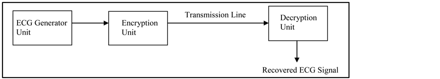
Figure 1. General organization of the EDS.
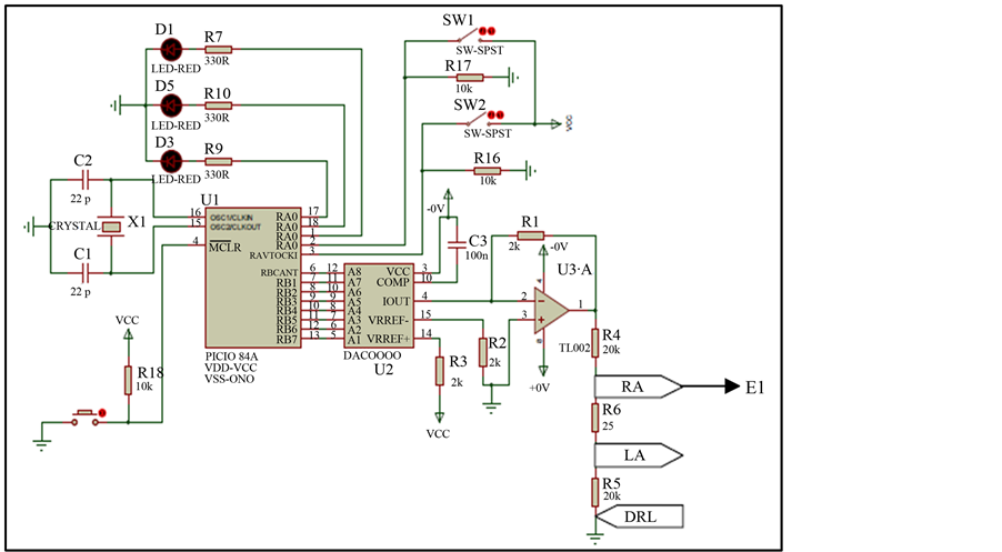
Figure 2. The ECG Generator Unit [17] .
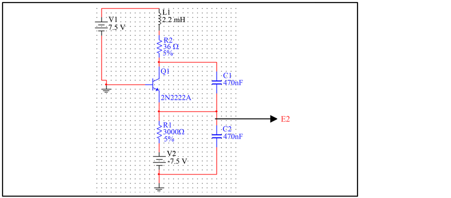
Figure 3. The colpitts oscillator used.
Let’s assume that U1 is the voltage across C1 and U2 the voltage across C2. Applying Barkhausen criterium to this oscillator, the resonance frequency f0 can be computed
 (1)
(1)
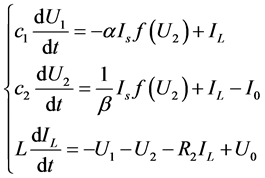
Applying Kirchhoff current and voltage laws to the circuit, we have:
 (2)
(2)
where α and β are the BJT parameters:  and
and  is the current of emitter with
 .
.
Let’s introduce some dimensionless variables for convenient numerical analysis:

The first equation of system (2) becomes:
 (3)
(3)
 (4)
(4)
We consider  as control parameter.
Posing  (5)
(5)
we transform Equation (4) into Equation (6).
 (6)
(6)
Similarly, with these changes in variables, the second equation of the system (2) is transformed into equation (7).
 (7)
(7)
with .
.
The third equation becomes:
 (8)
(8)
Finally, the set of Equations (2) is transformed to set of Equations (9)
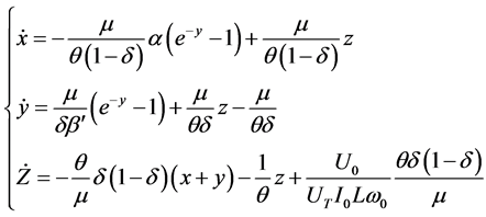 (9)
(9)
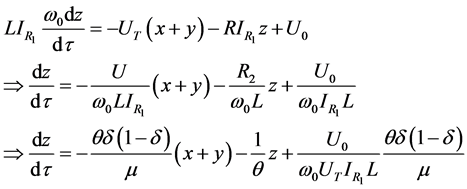
where (.) denotes the partial derivative. A change of origin led to the set of Equations (10).
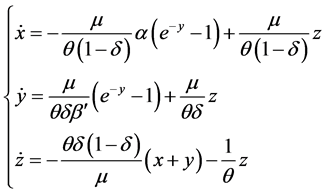 (10)
(10)
The nature of the solution of set of Equations (10) strongly depends on the control parameter μ.
Using fourth order Runge-Kutta to resolve the system (10), we realized that for
•  the system tends to stabilize around a single frequency value•
  the system oscillates between two frequency values• from
  many bifurcations points appear and the system exhibits a chaotic behaviour.
From Equation (5), we can see that μ is a function of the current and the elements of the Colpitts circuits. Deducing the current  for which there is chaos in the circuit is therefore straightforward, given a quadruplet (R2, L, C1, C2).
2.2.2. Encrypting and Multiplexing Subunit
This subunit is made of an adder whose inputs are the ECG signal and the chaotic signal from the Colpitts oscillator. The output of the adder is sent to one output of a 2-to-1 multiplexer while its second input receives once more the chaotic signal from the Colpitts generator. The encrypting and multiplexing subunit is depicted in Figure 4.
2.3. Decryption Unit
The decryption unit is made of a 1-to-2 demultiplexer whose two inputs are connected to the two inputs of a subtractor. The output of the substractor is sent to a low-pass filter whose output yields the decrypted ECG signal. Figure 5 gives the decryption unit.
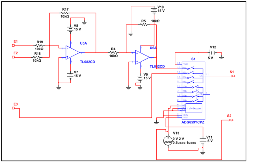
Figure 4. The encrypting and multiplexing subunit.
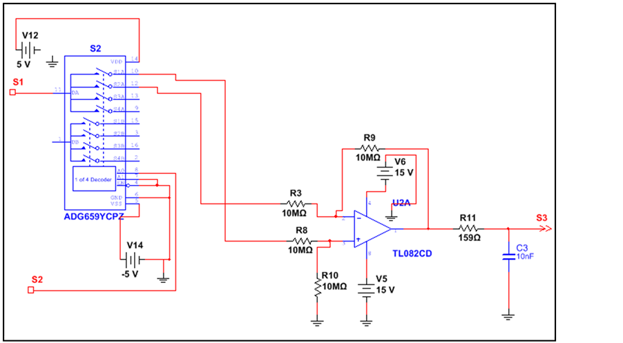
Figure 5. The decrypting unit.
3. Results and Discussion
3.1. Chaotic Behaviour
The colpitts oscillator has been well researched in the literature. Its main role is to generate chaotic oscillations that are added to the signal to be hidden. In our experimental setting, the value of the current  injected in the system is varied and voltage drops across capacitors C1(VC1) and C2(VC2) are displayed on the oscilloscope. The value of C1 and C2 is 470 nF, inductor L value is 2.2 mH while R2 value is 36 Ω. The supply voltages are 7 V for U0 and −7.5 V for U3. We realized during our experiments that:
For  the signal generated by the Colpitts circuit is periodic.
For  the signal generated by the Colpitts circuit is multiperiodic.
For  the system generate a chaotic signal.
We can see that the waveforms change according to the current’s value until the chaotic state is reached as shown below by waveforms VC1 and VC2 for a current of 7.6 mA (Figure 6) and phase diagram (Figure 7). The bifurcation diagram obtained [18] as the current varies is plotted below (Figure 8).
A usual test for chaos is calculation of Lyapunov exponents. It is common to refer to the largest one as the Maximal Lyapunov exponent (MLE), because it determines a notion of predictability for a dynamical system. The Lyapunov exponents give the average exponential rates of divergence or convergence of nearby orbits in the phase-space. In systems exhibiting exponential orbital divergence, small differences in initial conditions which we may not be able to resolve get magnified rapidly leading to loss of predictability. Such systems are chaotic. In Figure 9 is plotted the dynamic of Lyapunov exponents for the colpitts oscillator used. For initial conditions (x = 0.2, y = 0.5, z = 0.5), the system being solved by means of 4th order Runge Kutta technique, with Step 0.01, three values of Lyapunov exponents (Lamda 1, Lamda 2, Lamda 3) are obtained: Lamda 10.1 (positive value), Lamda 2 = 0.0, Lamda 3 = −0.70 (negative value). These results validate the bifurcation diagram of Figure 8 and prove the chaotic nature of the oscillator [18] .
3.2. Signal Encryption and Multiplexing
The signal yielded across resistor R6 of the ECG generator (Figure 2) is injected at the input E1 of the encryption unit (Figure 4) while the chaotic signal studied in the previous subsection is injected at the inputs E2. At the output S0, the encrypted ECG signal is collected. Figure 10 and Figure 11 display the original ECG signal and the encrypted ECG.
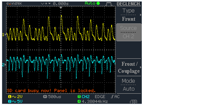
Figure 6. Voltage waveforms from VC1 and VC2.
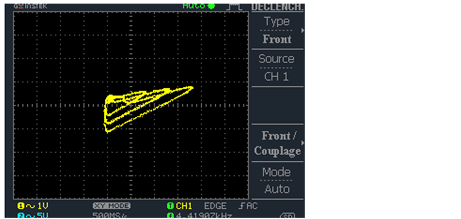
Figure 7. Phase diagram.
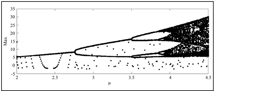
Figure 8. Bifurcation diagram.
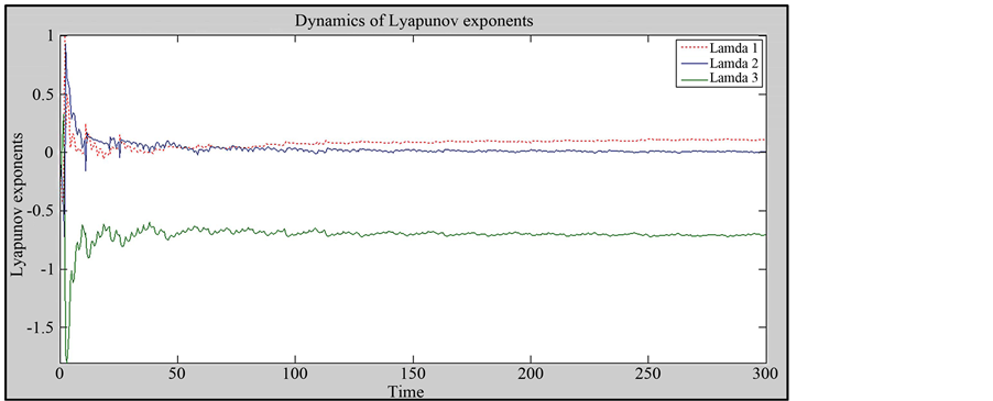
Figure 9. Dynamics of Lyapunov exponents for the oscillator.
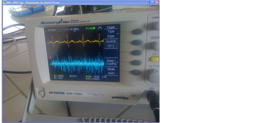
Figure 10. ECG original signal: the upper signal is the original ECG.
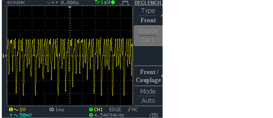
Figure 11. Encrypted ECG signal.
After encryption, the signal is sent to one input of a 2 to 1 multiplexer while the other input receives the chaotic signal. The output of the multiplexer is S1 and is displayed in Figure 12.
The multiplexed signal is sent on the transmission line and gets to the decrypting subunit whose results are given in the next subsection.
3.3. Decrypting Unit
The signal enters this unit by a 1-to-2 demultiplexer (DMX) who receives the encrypted ECG. The two outputs of the DMX are sent to the substractor whose output is sent to a low-pass filter in order to retrieve the hidden ECG signal. The result is shown in Figure 13.
3.4. Discussion
Visually, there is a good level of concordance between the original and the decrypted ECG as can be seen from Figure 13. The mean quadratic error of the two signal was computed and we found a value of 1, 33. The error committed during signal retrieval is therefore less than 2%. ECG signals are generally in the order of 1 to 5 mV before amplification. There is averagely therefore a difference of 20 to 100 μV between the two signals which is acceptable. The quality of recovered signal is linked to the filter. In our case, a low pass filter is used. We obtained the results with 2 set of values for resistor R11 and capacitor C3 of the filter. When R11 = 159 Ω and C3 = 10nF, the decrypted signal is visually good, but it still contains noise (Figure 14). For R11 = 1 KΩ and C3 = 10
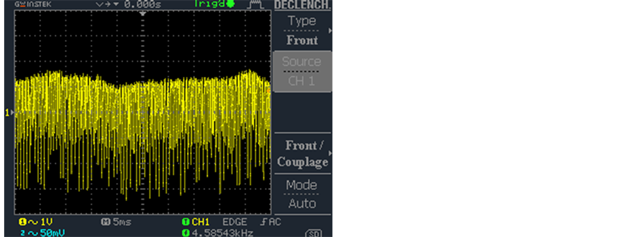
Figure 12. Multiplexed signal.
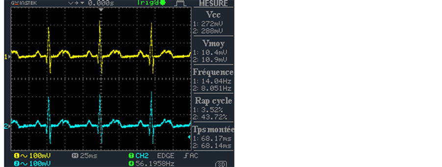
Figure 13. The upper signal is the retrieved (decrypted) ECG signal for R11 = 1 KΩ and C3 = 10 μF while the lower one is the original ECG.
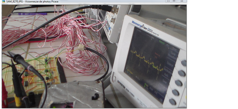
Figure 14. The signal is the retrieved (decrypted) ECG for R11 = 159 Ω and C3 = 10 nF.
uF, the quality of decrypted signal is visually very good as we can observe on Figure 13 as compared to the original ECG.
We also computed the signal to noise ratio and found 25.50 dB. This value is an indication of the level of corruption of the signal by noise. The noise is therefore about twenty times smaller than the signal carrying the information. The system therefore yields a good margin. The last metric that was computed to numerically evaluate the resemblance is the frequency distortion which a measure of how far the recovered signal has drifted from the original signal frequency-wise. We found a value of 6 × 10⁻⁴. This value shows there is really no frequency drift between the two signals.
The three metrics computed permits us to conclude that both visually and numerically, the concordance (resemblance) between the two signals can be termed as good.
During our experiments, for to the value of C1 = C2 = 470 nF, we observed that when R1 ≤ 300 Ω or R1 ≥ 2000 Ω there is not chaos in our system. With the appropriate values of C1, C2 and R1, we also lost chaos when L ≤ 2.1 mH and L ≥ 5 mH.
We noticed that the range of multiplexer/demultiplexer frequency for which the hidden signal is well decrypted is 53.3 Khz to 850 Khz. For frequencies out of this range, we had only noise at the receiver. Furthermore, it was completely impossible to retrieved the hidden signal when the working frequency of the multiplexer was different from the one used by demultiplexer. This aspect enhances the security of our system. The experiment of transmission in this work was tested on a distance of 45 m.
4. Conclusion
In this paper, we have designed and tested a very simple chaos-based encryption system for a very delicate and common medical signal. The system was designed on the basis of some shortcomings of earlier techniques. The results in terms of mean quadratic error signal to noise ratio and frequency distortion are satisfactory. In future works, we wish to examine the effect of the transmission conditions on the recovered signal, namely non-linearity in the propagation line, type and level of noise and then radiofrequency transmission.
References
- Pecora, L.M. and Carroll, T.L. (1990) Synchronization in Chaotic Systems. Physical Review Letters, 64, 821-824. http://dx.doi.org/10.1103/PhysRevLett.64.821
- Kolumban, G., Kennedy, M.P. and Chua, L.O. (1998) The Role of Synchronization in Digital Communications Using Chaos—Part II: Chaotic Modulation and Chaotic Synchronization. IEEE Transaction on Circuits and Systems-I: Fundamental Theory and Applications, 45, 1129-1140.
- Kennedy, M.P. (1993) Three Steps to Chaos—Part I: Evolution. IEEE Transaction on Circuits and Systems I, 40, 640- 656.
- Fujisaka, H. and Yamada, T. (1983) Stability Theory of Synchronized Motion in Coupled Oscillator Systems. Progress of Theoretical Physic, 69, 32-47. http://dx.doi.org/10.1143/PTP.69.32
- Rulkov, N.F., Sushchik, M.M., Tsimring, L.S. and Abarbanel, H.D. (1995) Generalized Synchronization of Chaos in Directionally Coupled Chaotic Systems. Physical Review Letters, 51, 980-994.
- Kocarev, L. and Parlitz, U. and Stojanovski, T. (1995) Generalized Synchronization of Chaotic Signals. Proceeding NOLTA’95, Las Vegas, 953-956.
- Kennedy, M.P. and Dedieu, H. (1993) Experimental Demonstration of Binary Chaos-Shift-Keying Using Self-Synchronising Chua’s Circuits. Proceedings of the Workshop of Nonlinear Dynamics and Electronic Systems, Dresden, 23rd- 24th July 1993, 67-72.
- Dedieu, H., Kennedy, M.P. and Hasler, M. (1993) Chaos Shift Keying: Modulation and Demodulation of a Chaotic Carrier Using Self-Synchronizing Chua’s Circuits. IEEE Transaction on Circuits and Systems: Part II: Analog Digital Signal Process. (Special Issue), 40, 634-642.
- Kennedy, M.P., Kis, G., Jákó, Z. and Kolumbán, G. (1997) Chaotic Communications Systems for Unlicensed Radio. Proceedings of the NOLTA’97, Honolulu, 29th November-2nd December 1997, 120-124.
- Kolumbán, G. and Vizvari, B. (1995) Nonlinear Dynamics and Chaotic Behaviour of the Analog Phase-Locked Loop. Proceedings of the 3rd International Workshop on Nonlinear Dynamics of Electronic Systems, Dublin, 99-102.
- Kolumbán, G., Vizvari, B., Schwarz, W. and Abel, A. (1996) Differential Chaos Shift Keying: A Robust Coding for Chaotic Communication. Proceedings of the 4th International Workshop on Nonlinear Dynamics of Electronic Systems, Sevilla, 27-28 June 1996, 87-92.
- Kolumbán, G., Kis, G., Jákó, Kennnedy, M.P. and Jákó, Z. (1997) FM-DCSK: A New and Robust Solution to Chaos Communications. Proceedings of the NOLTA’97, Hawaii, 117-120.
- Kolumbán, G., Kis, G., Jákó, Z. and Kennnedy, M.P. (1998) FM-DCSK: A Robust Modulation Scheme for Chaotic Communications. IEICE Transactions on the Fundamentals, E-81A, 1798-1802.
- Galias, Z. and Maggio, G.M. (2001) Quadrature Chaos Shift Keying. Proceeding IEEE International Symposium on Circuits and Systems, ISCAS’01, 3, 313-316.
- Galias, Z. and Maggio, G.M. (2001) Quadrature Chaos-Shift Keying: Theory and Performance Analysis. IEEE Transactions on Circuits and Systems-I: Fundamental Theory and Applications, 48, 1510-1519. http://dx.doi.org/10.1109/TCSI.2001.972858
- Masuda, N. and Aihara, K. (2002) Cryptosystems with Discretized Chaotic Maps. IEEE Transaction on Circuits and Systems-I, 49, 28-40. http://dx.doi.org/10.1109/81.974872
- Tchimmoue, G.E., Kamdem, J. and Nko’o, A.S. (2012) Didacticiel d’Instrumentation Virtuel à Coût Réduit pour l’Acquisition et le Traitement des Signaux ECG. Journal sur l’enseignement des sciences et des techniques de l’information et des systèmes J3EA, 11. http://www.j3ea.org/articles/j3ea/pdf/2012/01/j3ea12002.pdf
- Kenfack, G. and Tiedeu, A. (2013) Secured Transmission of ECG Signals: Numerical and Electronic Simulations. JSIP Journal of Signal and Information Processing, 4, 158-169. http://www.scirp.org/journal/PaperInformation.aspx?paperID=31000#.UwYDfc7t-_I http://dx.doi.org/10.4236/jsip.2013.42023