Journal of Biomedical Science and Engineering
Vol. 5 No. 8 (2012) , Article ID: 21460 , 12 pages DOI:10.4236/jbise.2012.58058
Functional design method for improving safety and ergonomics of mechanical products
![]()
1Research Institute on Transportation, Energy and Society (IRTES-M3M), University of Technology of Belfort-Montbéliard, Belfort, France
2DDMEM, University of Strathclyde, Glasgow, Scotland
Email: *aurelie.robert@utbm.fr
Received 4 May 2012; revised 5 June 2012; accepted 19 June 2012
Keywords: Ergonomics; Design; Finite Element Analysis; Design Methodology; Biomechanics
ABSTRACT
In order to help companies to improve their competetiveness, it is important to develop new design methodologies. In this framework, a Functional And Robust Design (FARD) methodology dedicated to routine design of “highly productive” modular product ranges is proposed including principles of functional analysis, Design For Assembly (DFA), and techniques of modelling and simulation for ergonomics consideration. This paper focuses on the application of this original method applied to mechanical vibration and ergonomics problems of a scraper. Including biomechanical aspect in the design methodology, it is possible to identify the impact of a vibration tool on its users using numerical models of the tool coupled to a finite element model of the human hand. This method can proactively warn very early, in the design process, the risks of causing musculoskeletal disorders and facilitate an optimization of the mechanical tool. This study is a first step in a context of human-centered design.
1. INTRODUCTION
Nowadays, ergonomic aspects of product realisation are increasingly taken into account by companies. Institutions focus on the importance of human factors to protect the health of employees with prevention campaigns. Thanks to these campaigns, companies become aware of the importance of tools that can be easily used by their employees. Moreover, European Parliament and Council impose directives and standards in order to protect workers’ health. So products must meet more and more ergonomic constraints. Most of time, companies use physical tests to check these constraints. The disadvantages of real tests are: high costs of prototypes, time to manufacture prototype, difficulty of modification, complex protocols with human subjects. Indeed, for each real test, one new prototype is manufactured specifically for that single occasion. To reduce delay, costs, number of prototypes and other constraints, numerical human models [1-3] can be used to analyze the impact of design choices on human body. Industry is more and more becoming the users of these human models, but they must be as close as possible to the physical reality of human behaviour. Several teams or European projects work on the development of virtual human models [4]. Most of these models take into account degrees of mobility of the human body (kinematical aspects) [5-7], but it is more difficult to consider dynamical phenomena, such as: forces, accelerations, constraints, etc., linked to biomechanical aspects.
This paper focuses on digital simulation of tool vibrations with a virtual model of a human hand in order to analyze the impact of design choices on the user’s wrist articulations. MABI Company develops a new modular range of pneumatic scraper, a hand tool that generates vibrations during its use phase. In order to develop a family of scraper products, a new design methodology is developed. This methodology, called “Functional And Robust Design (FARD) method” [8] aims to define a range of modular product which respects customer needs and helps to co-define an optimal product architecture and assembly sequence. Modelling and simulation steps are undertaken in previous stage of process design. At this stage of our approach, a none-detailed definition of the product is used on the early steps of the design process. In this context, digital human models guide designers on decision making and design choices. Our global objective is to improve the optimization steps of virtual products, by using Finite Elements modeling and simulation loops, during the detailed design phase of the product [9], before launching the prototyping phases, by using a para-metric design, modeling, optimization and simulation approach. Depending on the problem to solve, mono-objective or multi-objective optimization methods and tools can be applied, in interaction with the previous Finite Elements models of the pro. As products become increasingly complex, their design process is usually characterized by numbers of design variables, parameters, requirements, and also geometrical, physical…, constraints (structural, vibration, thermal…) and objective functions. Engineering design of complex systems is a decision making process that must select the best solutions among a set of options leading to an irrevocable allocation of resources. It is inherently a multi-objective optimization process.
The new range of pneumatic scrapers developed by MABI company needs to respect large number of constraints and particularly a new European directive on vibrating tools. The directive imposes a maximum mechanical vibration level, in order to protect users from risks of musculoskeletal diseases. In order to check the entire family of the new pneumatic tools and to analyze very early on the design process the impact of vibrations, our self-developed digital biomechanical hand model will be applied [10]. Currently, this digital model is developed as stand alone model but its final goal is to simulate virtually its behaviour in interaction with digital mock-up of the product. A finite element model of the hand constructed uses hyperelastic constitutive laws to represent soft tissues of hand and bones in order to verify as close as possible the physical reality of a human hand. This biomechanical hand model allows us also to simulate the ergonomics of pneumatic scraper handgrips. Usability is an important aspect for the Mabi Company. Indeed, comfort, safety and health can make the difference for customers between two similar products. Moreover, an ergonomic handgrip, linked with an anti-vibration system, can contribute to protect the health of users by reducing risks of musculoskeletal diseases.
The paper begins by presenting a literature review, considering in next subsections, product design methodologies, design for ergonomics approach and current research on biomechanical models for human-centered design application. In Section 2, our contribution with the Functional and Robust Design (FARD) method using dynamic biomechanics hand model is described. The FARD method includes a biomechanical modelling and simulation loop, in order to appreciate the result of design choices on the end-users’ health. In Section 3, a case study describes the FARD method applied on a pneumatic scraper, illustrates the proposed concepts, followed finally by the conclusions.
1.1. Product Design Methodologies
Design methods, within the framework of process engineering, have been described by many authors in order to reach a solution by starting from a problem, or in order to provide to a detailed product definition by starting from a concept. These methods try to build various sequences of design activities to be performed by different design actors (marketing, industrial design, design office, quality methods, production...) to achieve a final goal: a marketable product that meets the customer needs.
Among many models of product-process lifecycle design in the literature, it is possible to identify two types of models that can be described: sequential models or concurrent models.
Sequential models of the product-process lifecycle design are divided into phases or tasks that follow one another, sometimes connected with a Work Breakdown Structure [11]. It is a decomposition process that corresponds to a version of the traditional engineering activity organization, inheritance of Taylor’s concepts classically applied to manufacturing process. Generally, each phase or task starts only if the previous task is completed. These phases or tasks will allow each life actor to deal with its part of the problem before transferring the project data to the next business unit. Sequential models of the product-process lifecycle design contribute also to maintain a boundary between the various engineering services company.
One of the well known sequential models is the Systematic Design model [9]. This model is based on the succession of four phases mainly focused on product definition: Clarification of the task, Conceptual Design, Embodiment design and Detail Design. In the Clarification of the task the problem and information about the product are collected. The specification of functions and properties for the new product are defined. So all next phases of the design process will be based on these specifications. During the Conceptual Design phase, solution principles are founded according to specifications defined in the previous phases of the Systematic Design model, in order to build a concept, including the product architecture. During the Embodiment design phase the chosen concept and its architecture are refined and transformed into a definitive Product design. During the Detail Design phase the product and all its individual components are fully specified. In the end, all product documents for manufacturing and assembly are produced. In each phase, one or more documents are expected, for example: specifications, concept, preliminary layout, definitive layout…
Other sequential models such as the Ullman design process [12] or the Total Design process, proposed by Pugh [13], have their own specificities and add, for instance, various feedback loops, at different levels of the model.
With the evolution of industrial constraints such as the need to increase quality while reducing costs and time, sequential design process models have been questioned. The evolutions of digital tools and communication infrastructures have contributed to the development of new design organizations and models. These new models of design process have also been called concurrent [14], integrated [15], distributed [16], or collaborative engineering. The main characteristics of these various methods are:
· integration of constraints related to the product entire lifecycle earlier;
· concurrent implementation of the product development and its manufacturing process;
· parallel realization of the tasks required to perform the design process;
· reduction of design delays and collaboration improvement between the various design contributors, involved in a single integrated design team.
This collaboration between various stakeholders within the same team has contributed to the evolution of Industrial habits. Therefore, the design process has also been improved towards a multi-dimensional and multi-craft design process because project managers can consider many points of view coming from various domains. Among the models of concurrent engineering, and through the “axiomatic design” approach [17], another way of improving the product design process has been identified, if designers decide to respect specific rules, also called axioms. This axiomatic approach is based on various axioms (example: axiom of independence, axiom of minimum information, etc.) applied in four Design domains (Customer Domain, Functional Domain, Physical Domain and Process Domain).
Another approach concerns also the multi-viewpoints model of the product considered as an integrated design method of products or mechanical [15]. This multiviewpoints model is used, in particular, to define the interfaces with the external elements or components of a mechanical system. This approach is based on the product architecture and on the combination of various viewpoints of the system: functional, structural, geometrical, machining, assembly, etc.
Finally, the design process model based on Andreasen’s Theory of Domains (ToD) was proposed. However [18], this model is based on four domains, each of them representing a level of abstraction of the product going from a global to a more detailed product definition. The domains are realized gradually as the design progresses.
Our design process model, based on the research work proposed by Gomes and Sagot [19], and called Multidomain and Multi-viewpoints design model, can be described as a collaborative design process model, integrating concepts coming from Axiomatic design and multi-viewpoints model. This model considers that a design project, in the field of mechanical system engineering, is a network of various interacting design domains such as Project, Product, Process, Usability, etc. Each of these design domains can be examined from several viewpoints (or aspects) in interaction such as:
· functional viewpoint, which describes the main objectives and goals of the system;
· structural viewpoint, defining the system elements and architecture;
· dynamic viewpoint, which describes the chronological behaviour of the system.
In this configuration, other design viewpoints, such as the physical or the geometrical one, are directly linked to the structural aspect of the system.
The particularity of this design methodology is that it considers human activities (users, manufacturers, etc., activities), as an effective design domain (usability domain), linked to the other Product, Process and Project domains. This usability dimension is integrated into our approach in order to have a better integration of human factors in the early steps of the design process.
Concerning the theoretical models underlying the design process, three kinds of models can be used: the perspective models, the computational models and the knowledge based models [20]. Our approach is located in the scope of computational models, requiring the use of computers to determine the best feasible values of design variables, using Constraints Problem Solving, when considering expert knowledge (parameters, rules, etc.) linked with modelling, simulation and optimization approaches, when analyzing the impact of Multi-physics solicitations on the product. The objective of such an approach is to maximize or minimize various objective functions using multi-objectives optimization and simulation techniques. A multi-objective optimization problem can be described as finding the vector of design variables x = [x1, x2, x3,···, xn]T which minimizes the vector of objective functions F(x).
Min F(x) =Min[f1(x), f2(x), ···, fk(x)]
Subject to linear or non-linear constraints: Gj(x) ≥ 0, j = 1, 2, ···, m.
1.2. Design for Ergonomics Approach
For a best design for the product, end-users must be considered at the early stages of the design process with ergonomic requirements and rules. Customer needs analysis and end-user requirements analysis must be applied at the first steps of the design process to be more efficient and less costly. End-user needs are often integrated in the design process in the detailed design phase or during the last tasks of testing the various prototypes. But it is often too late, because the design of the product is finalized and it is difficult to change at such a late stage, due to the costs and the delays increase for the product and for the project. Ergonomists, when using Design for Ergonomics methods and tools, can help designer to evaluate impacts of their solutions on human end-users of the products. This Design For Ergonomics approach is not only performed to reduce product’s costs and project delays but also to improve the quality of use and the safety of products [21]. Ergonomists must ensure a match between the optimal usability conditions of the new product and the safety conditions for the future users.
To sum up, generally ergonomists use standards and tests to verify the usability of new products. Our work proposes to replace much of the real and expensive tests by simulation. A relevant simulation can replace physical model and can detect errors earlier in the design process. Digital tools like numerical models based on Finite Elements methods can help designers to consider human factor when simulating the Man-Machine-Environment system’s interactions. Digital human model can represent a future user, can simulate how the user interact with the product using conditions of the product, and can evaluate interactions with its environment, etc in order to define information about constraints impacting on the human body during the use of the product.
The MANERCOS human digital model [22] considers only the usability function with an anthropometrical, geometrical and kinematical point of view [23]. Indeed, through the MANERCOS development performed in 2003, only the geometrical aspects have been considered and defined different degrees of freedom for the joints of the human digital model.
Other research team develops biomechanical aspects on a human digital model, as in the DHErgo project. Its aim is to develop human musculoskeletal digital models to evaluate the physical aspects of a product in its design stage by simulation of critical postures or movements. The DHErgo project stakeholders want to realize a muscular skeletal human model that will be mainly capable of estimating muscle forces. The results of the project are an evolution of the current kinematic digital human model to dynamic and muscular models. This new kind of models would help designers for motion simulation and discomfort assessment in comparison with the current digital human models such as geometrical and kinematic models. Muscular effort and expenses incurred by the soft tissue will be taken into account. As a first result in this area, it is possible to notice that Fraysse et al. [24] have developed a model of a lower limb with thirty muscles tested during a clutch pedal operation.
Other mathematical biomechanical model have been developed in the literature, focusing on various point of view: force with kinematic [25], contact stress distribution in the wrist bones [26], or its stability [27].
Our new approach intends to extend this vision by considering now the forces involved during the human activity when interacting with the product, which corresponds to a dynamic view of the model including the ability to investigate kinematic, local stress and contact forces with a biofidelic FE model of the hand. Then, musculoskeletal disorders can be investigated.
1.3. Biomechanical Model for Human Centered Design Application
Human centered design becomes essential and one cannot avoid taking into account ergonomic aspects whatever is the industrial context [28]. For that reason, Finite Element (i.e. FE) simulations appear to be an interesting and powerful tool to extend its normal intended use into an ergonomic system, in order to improve the its ergonomy and its design based on biomechanical injury criteria.
For the current study, a finite element model of the hand is developed. This model uses hyperelastic constitutive laws and allows representing soft tissues of the hand. This hand model for an efficient design process is an improvement of a finite element model of the hand previously developed with a single layer of soft tissue [29]. The benefit of the new model is the improvement of its biofidelity, as it includes finger bones and wrist bones with specific elastic constitutive law.
The FE model has been built from Computed Tomography (CT) scan slices performed on a male subject. The medical exam has no links with the present study. The model (Figure 1) consists in 17,700 elements consisting of 1700 elements in wrist’s bones, 2000 elements in fingers’ bones and 14,000 elements for the skin.
Constitutive laws of the hand are extracted from literature Rho’s work is used for bones elastic properties [30], and complex HGO properties are used to model the skin [31]. Loadings induced by the mechanical system are transmitted to the hand which can be injured if the loadings are too important (impacts, vibrations). Then,
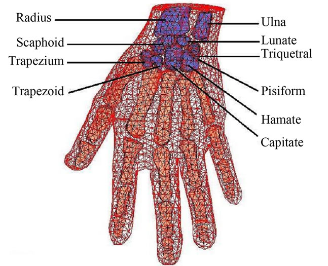
Figure 1. Illustration of our self-developed finite element model of the hand.
the mechanical system can be optimized in order to reduce the risk of injuries in the hand (inclusion of damping system or springs in the system). So the numerical analysis of the mechanical system in interaction with the hand, with the FE method, can lead to improve its design for a human centered development of mechanical systems.
2. FUNCTIONAL AND ROBUST DESIGN (FARD) METHOD USING BIOMCHANCAL SIMULATION
2.1. Functional and Robust Design Method (FARD)
The objective of the proposed FARD model in Figure 2
[8] is to define a range of modular product respecting the best assembly sequence for the product family while checking the correspondence with the functions of the product and the proper keeping mechanical of this range. This method is considered as robust due to the stability of its reuse on other use-cases and in other domains.
This methodology can be applied on two types of projects. The first type of projects is based on the desire to develop a new range of modular product based on an old none-modular range of products. A company could want to rejuvenate one of its products’ family. The second type of projects consists of developing a new generation of products dedicated to generate, in the future, a new products’ family. The definition of the range of products
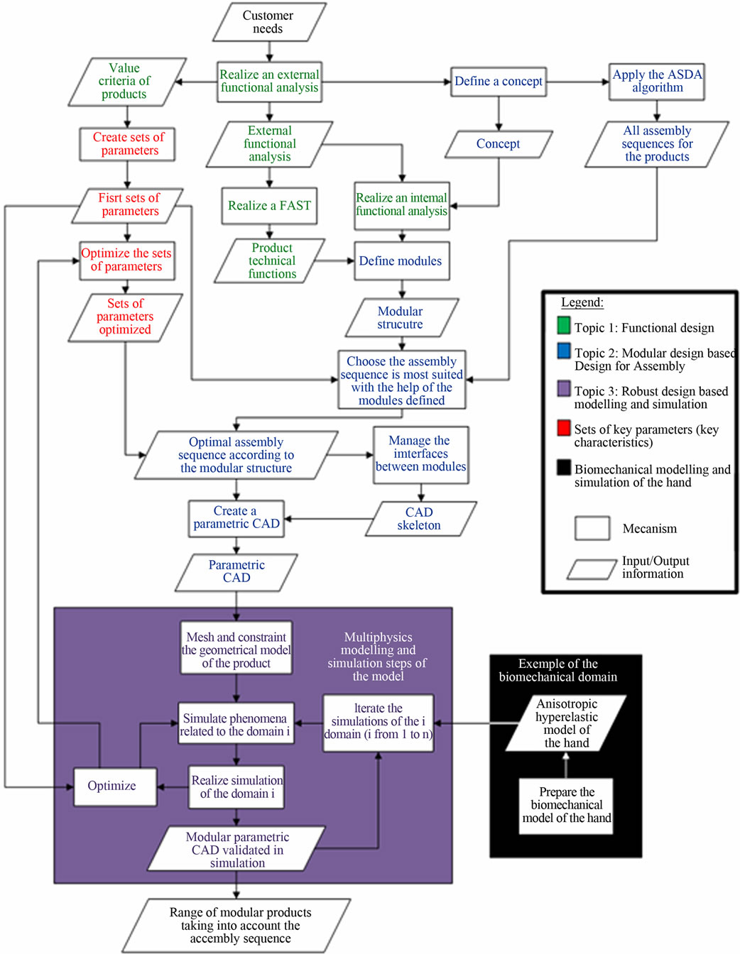
Figure 2. Proposed FARD model including a biomechanical modelling and simulation loop to appreciate the impact of the product on the users’ health.
is made at the early phase of design process [9], before the detailed design phase of products. The entire first part of the approach applies to a concept in the preliminary phase of the development process. For this, the overall architecture of the modular range is defined as a result of an external and internal functional analysis [32]. Modules are specified from this functional analysis of the product. Authors define a module as an independent functional component or group of components which correspond to a technical function and these modules can be assembled independently. It is like separate functional modules. Then the functional analysis allows defining the modular architecture of products of the range. The goal of the FARD model is to share components among the modules in order to create a modular structure that facilitates the generation of variants of each module. These variants can respond to specific customer needs.
In parallel, from the definition of the concept, partitioned matrices are generated to define sets and sub-sets of components taking into account the relational information between components of a concept. Then the modular structure based on the functional analysis regroups main components in each module according to the correspondence between modules and sets of components. The next step is the application of the algorithm detailed by Robert et al. 2011 [33] that generates the eligible assembly sequences, taking into account the relational information between components of a product, from the upstream phase of the development process [34] and the modular structure, linking modules and their main parts, functions and sets of components. The purpose of the proposed algorithm is to filter the various eligible assembly sequences in order to guide the planner to choose the most suitable assembly sequence. The assembly sequence and parametric CAD can then be made by managing the interfaces between modules to ensure maximum standardization. At this stage, the process of development moves from the preliminary phase to the detailed phase of the design process. For the products being defined, multi-physics simulation may finally be deployed to evaluate the performance of the product in its lifecycle and if products respect limit value of mechanical vibration imposed by the European directive [35]. Respecting European directive is becoming more and more important for competitive companies. For this reason, our research work tries —to simulate vibration in order to help the MABI Company to respect the imposed vibration rates. If a product doesn’t respect the normalized level of usage, a user cannot use this product eight hours per day. Customers will therefore be less likely to buy this product.
As described in the FARD model, the main topic of this paper is concerned with the robust design approach, based on modelling and simulation loops in the product mechanical structure and in the biomechanical model of the users’ hand. This approach is performed in order to check and validate the maximum level of mechanical vibrations generated by the range of products. This maximum level is defined during the functional analysis phase and detailed through the design parameters, which can be directly connected to the parametric CAD model.
Multi-physics simulation is mainly used to validate the complete physical behaviour of the developed product. In our case, the products developed must resist, transmit or absorb various physical loads such as mechanical structural solicitation, vibration generation and transmission, shocks absorption. First goal of our study is to define an optimal design that can reduce the mechanical vibration level transmitted to the users’ hand, in order to decrease the risk of generation of musculoskeletal diseases. The other goal is to ensure that all variants of the product respect the requirements of the functional analysis, including ergonomic, safety and health preservation criteria.
2.2. Analysis of Mechanical Vibration Level to Decrease the Risk of Musculoskeletal Disorders
The typology of hand-tool described in this paper produces mechanical vibration. But the hand-tool vibrations, transmitted to the wrists, elbows, shoulders, etc. can impact negatively on the health of users. Hands and arms of the workers are exposed all day to mechanical vibration and year after year they can create health troubles or diseases. Musculoskeletal disorders result in painful symptoms for employees and a reduced functional ability, often temporally but sometimes permanent. Musculoskeletal disorders are multi-factorial diseases that affect the professional component soft tissues, like tendons and nerves of the hand (Figure 3).
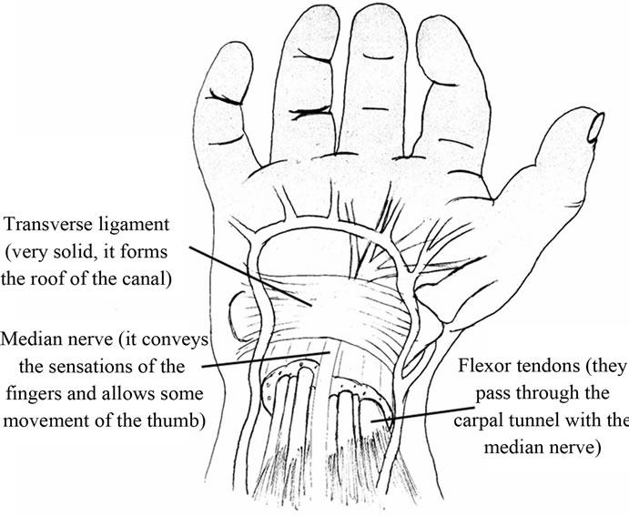
Figure 3. Soft tissues of a hand.
First, the musculoskeletal diseases result from the application of biomechanical constraints supported and/ or repeated during short or long periods and which exceed the functional ability of the user. They include all diseases linked with vibration exposure like tendinitis. These troubles are frequent when users regularly use a machine, a tool or equipment with a high level of mechanical vibration. Depending on the size and on the morphology of the user, musculoskeletal disorders can appear within days. Over last ten years, the number of troubles has increased very fast and represents today, the most part of all professional diseases. For example, many workers in the domain of building are more and more exposed to mechanical vibration. For these reasons, European parliament and the European Union council impose limit values for exposure using European directives. One of these directives is the European Machinery directive [35]. The EU Council Directive 2002/44/EC on the minimum health and safety requirements regarding the exposure of workers to the risks arising from physical agents (mechanical vibration), has been validated. It also creates a basic protection for all workers by detection of adverse health effects like musculoskeletal disorders.
This directive distinguishes vibration affecting the hand-arm-system from vibration being transmitted to the whole body. This paper will focus on values concerning the hand-arm-system based on a standard eight hour reference period of work, like for one day of work. The limit value of mechanical vibration imposed by this directive is 5 m/s². Beyond this value, employees can’t use their tool eight hour per day. But from 2.5 m/s², disorders and musculoskeletal diseases can appear. In Figure 4, it is possible to identify three areas defined by the directive. Mechanical vibration in the green area, delimited by the green curves, is the best for workers and the orange area is correct. But the red area, delimited by the red curves, is a totally proscribed vibration area.
For example, if one wishes to use a tool with an acceleration vibration of 8 m/s² and respect the limitation of the European directive, one can use this tool only for four and half hours per day according to the graph described in Figure 3. Beyond this time, the user is exposed to risk of musculoskeletal diseases.
The daily exposure A(8) can also be evaluated in Equation (1), γ is the acceleration vibration of the tool (m/s²) and t the real-time use per day. The A(8) calculated acceleration vibration level corresponding to 8 m/s², can directly be compared to the level of the European directive.
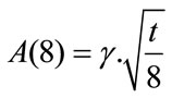 (1)
(1)
Many hand-tools or hand-guided machines generate mechanical vibration. For some, the vibration levels can be high, such as scrapers, breakers. Mechanical vibration level is defined by acceleration (meter per squared second, m/s²), frequency (Hertz, Hz) and amplitude (meters, m). Figure 5 shows various differences of acceleration between tools used in the domain of construction. It shows also that very few tools have their acceleration under the limit values imposed by the European directive (5 m/s²).
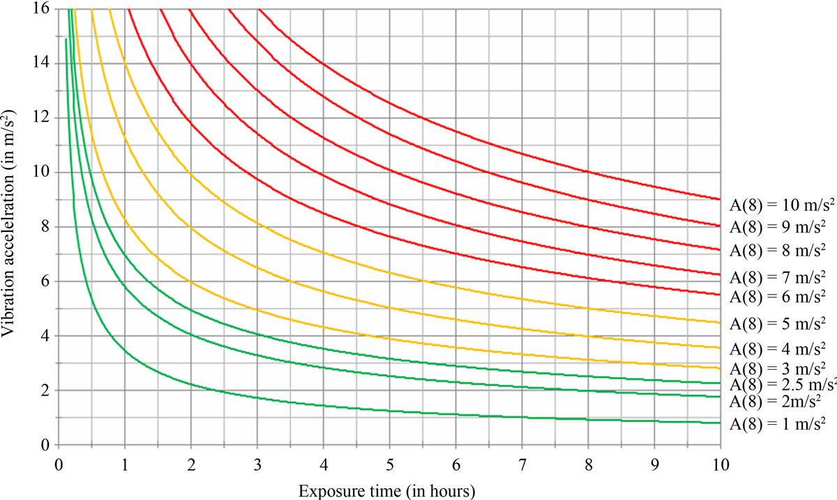
Figure 4. Areas of mechanical vibration level depending on exposure time of work, inspired from (Griffin et al. 2006 [36]).

Figure 5. Level of acceleration depending on the typology of tool, inspired from (Griffin et al. 2006 [36]).
In the case of the worker uses different tools per day with different level of vibration, it is possible to know if he is above the limit level imposed by the European directive.
The first step is to calculate the A(8) for each tool. Then Equation (2) can be used, 1 to n represents the A(8) of different tools for the day considered.
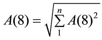 (2)
(2)
The risk of developing a musculoskeletal disease increases when the working situation presents a combination of biomechanical stress, psychosocial factors, work organization and personal equation. To reduce this risk, it is possible to reduce the stress of the working activity by acting on: tool design, product design, workplace design, production organization, work organization. In our case, it is important to consider these constrains fully during product design.
3. RESULTS AND CASE STUDY: PNEUMATIC SCRAPER COUPLED TO BIOMECHANICAL MODEL
In order to illustrate the methodology presented in the previous section, our study focuses on one pneumatic scraper, extracted from a range of products generated through the FARD functional and robust design method. Scrapers are used for cleaning surfaces such as walls or tiled floors. Figure 6 shows an example of a pneumatic scraper.
At the beginning, the proposed methodology, as described in Figure 2, starts with a CAD model, representing the old design of the product.
Our objective consists in designing an optimized new product, with better usability, better external shapes (position and shapes for handgrips) and respecting the European directive for the limit values of mechanical vibration. To obtain a new range of products, the methodology is proposed to use an external and internal functional analysis (EFA and IFA) to define the overall architecture of the modular range. The functional architecture matches to the modular architecture. Then it is easy to define each module because one module corresponds to a function and one sub-module to a technical function. In this case study, a pneumatic scraper has one main function and three sub-functions decomposed themselves into technical functions. In parallel, partitioned matrices are applied on the concept to define sets and sub-sets of components. From modular architecture, sets of components and the correspondence between modules and sets of components, our algorithm can generate eligible assembly sequences. Then, the planner can choose among the assembly sequence possibilities the most suitable according to his experience and his knowledge of the company assembly capabilities. Finally, the parametric CAD model can be made and multi-physics simulation will be deployed on parametric CAD products. The aim of multi-physics simulations are: verify the product behaviour and evaluate the respect of mechanical vibration level imposed by the European directive [35] thanks our biomechanical hand model. But this last step is still in progress.
At the end, the application of our methodology provides a range of products design information including modular assembly sequence, and simulation modules to meet specific functional requirements defined by the customer at the beginning of the project. Moreover, this new range respects the European directive about values of mechanical vibrations. This was checked using experimenttal measurements. For example, it is possible to design handles to be more ergonomic and subject to less vibrations for users, thanks to the new innovative anti-vibration system included (Figure 7).
Finally, a new range of modular products is obtained that:
· respects the customer needs;
· is more ergonomic;
· should produce less mechanical vibrations compared to the older products.
The proposed Functional And Robust Design methodology (FARD) helps us to improve the new family of products. In this new family, our engineering and research work focuses on the product’s usability for workers and on the level of mechanical vibrations. A new system that absorbs mechanical vibrations results from these various efforts. The proposed FARD methodology allows generating, in a high productive way, all the products of the range, starting from one first design of the product, integrating parameters and design rules.
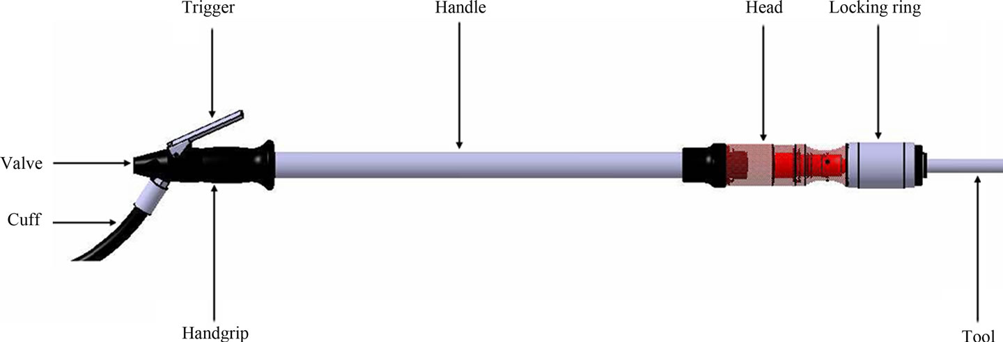
Figure 6. Example of pneumatic scraper.
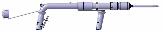
Figure 7. New functional and robust product.
The problem of human centered design applied to the hand and the gripping ability is very complex (Figure 8). The contact pressure between the hand and an object when operators handle the object using hand-held tools or planning and training aids, such as a haptic device, could be investigated by developing a non-linear 3-D finite element model of the hand and to derive optimized procedures for analyses.
At a numerical level, this gripping problem is very challenging because of the presence of strongly non-linear phenomena like contact between the hand and it environment, and hyperelasticity of the biological tissues [10]. The precise pressure map of the contacts and the dynamic change of these pressures are the critical focal point and computer aided simulation could provide a powerful tool to study contacts for many ergonomic centred studies for product, system and process development. In these applications, it is very important and interesting to evaluate the magnitudes and to determine the locations of these high pressures [37] which requires realistic modelling of the deformation of soft tissues.
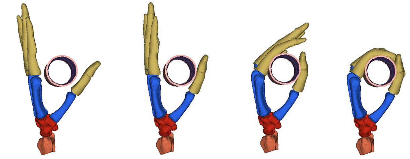
In that way of product design methodology based on human centered modelling, first simulations of gripping ability on a simple pad, have been performed in order to investigate contact stresses using the FE model of the hand. As illustrated in Figures 9(a) and (b), kinematic of gripping ability from a 0-energy state to a contact state has been simulated showing different step of the movement. Thus, from this simulation, internal stresses can be investigated especially for soft tissues, providing important data, allowing optimizing the shape of the pad,

Figure 8. F.E. model of the coupling of the biomechanical hand model with its environment (pneumatic scraper detailed in Section 3).
reducing the risk of musculoskeletal troubles.
From these simulations and the last step of gripping, vibration simulations can also be performed, investigating the influence of mechanical vibrations described previously. Inputting sinusoidal acceleration in the model, one can evaluate the dangerousness of the vibration on biological tissues according to Figures 4 and 5. This work is still under progress.
It is obvious that the act of gripping can be done in different way, with large contact force (in the case of a drill) or more softly (like gripping a bottle), and will necessarily lead to different contact force distribution. Even if these different cases of gripping have to be investigated at a biomechanical level, this first simulation illustrates the ability of the model to simulate a gripping activity, and its ability to be integrated in a more global design methodology in the framework of human central design.
4. DISCUSSION AND PERSPECTIVES
This paper presents a new approach to generate a new range of modular products which respects customer needs and usability constraints. A Functional and Robust Design (FARD) method is proposed. This FARD method permits generating a new family of products and the modelling and simulation steps allow improving the global
 (a)
(a)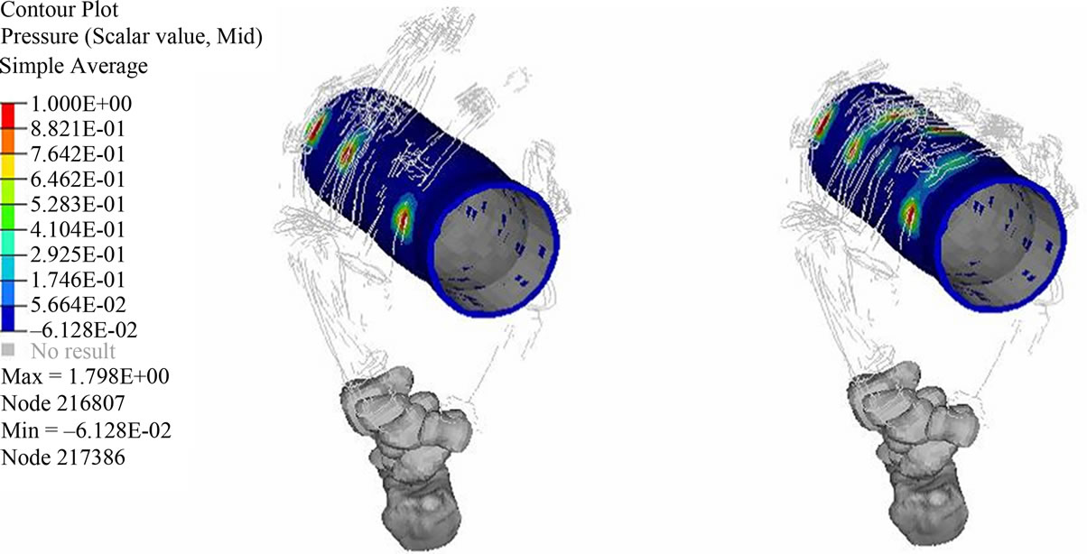 (b)
(b)
Figure 9. (a) Different steps of gripping: kinematic; (b) Mechanical parameters distribution for evaluation of contact forces.
usability of the studied scrapers.
Modelling and simulation can, at this stage, help us to optimize a new anti-vibration system and to increase its efficiency to better preserve the users’ safety and health, in conformity with the European directive.
Another aim of the simulation operation is to analyze the interaction of the geometric CAD model with the biomechanical hand model, in order to know the vibration impact on the user’s wrist and to evaluate the impact of the mechanical vibration on the carpal tunnel disease. The carpal tunnel syndrome is one of the most important musculoskeletal diseases that affect workers wellbeing in industry. Applying the proposed approach, it is possible to identify, very early during the design process, the impact of a vibrant tool on its user, only with the digital definition of the product. These simulation operations can be executed in order to investigate impact of decision choices on the user’s health in order to help designers to optimize their product before manufacturing prototypes.
The results of modelling and simulation of a biomechanical hand model combined with a vibrant tool are still in progress. The first modelling and simulation steps, considering the interaction between the biomechanical hand model and a vibrant tool, works. The hand model fits around the handgrip of a scraper and the global finite element model gives back interesting results.
The main goal of our approach is to integrate biomechanical simulation in a global design methodology. In the case of the scraper, the objective of the method is to develop and validate the tool and to generate all range of products, which will respects usability constraints, thanks to our FARD model detailed previously. So it will be possible to resize new products of the range and predict their future impact on future users before manufacturing any prototypes using biomechanical simulations.
Finally the FARD model is the base of the proposed methodology in this paper, which creates a mechanical framework in which ergonomics aspect and biomechanical numerical simulations are closely linked. Indeed, parametric aspects are brought in the process, with the objective of creating a range of product able to match the requirements in terms of safety, customer needs, biomechanics phenomenon:
· Safety represents the ergonomic part of the paper, with the inclusion of the musculoskeletal disorders due to the mechanical vibrations.
· Customer needs are taken into account in the FARD model to ensure the agreement between industrial product and initial requirements.
· Biomechanical phenomenon: Initial requirements impose a maximal level of mechanical loadings in the human body, regarding the exposure of workers to the risks from physical agents. These loadings are transmitted to the human body which can be injured if the loadings are too important. So the numerical analysis of the mechanical system in interaction with the hand, with the FE method, can lead an improvement of its design for a human centered development of mechanical systems. Then, the mechanical system can be optimized in order to reduce the risk of injuries in the human body.
![]()
![]()
REFERENCES
- Untaroiu, C.D., Meissner, M.U., Crandall, J.R., Takahashi, Y., Okamoto, M. and Ito, O. (2009) Crash reconstruction of pedestrian accidents using optimization techniques. International Journal of Impact Engineering, 36, 210-219. doi:10.1016/j.ijimpeng.2008.01.012
- Chaffin, D.B. (1988) Biomechanical modelling of the low back during load lifting. Ergonomics, 31, 685-697. doi:10.1080/00140138808966712
- Chaffin, D.B. (2005) Improving digital human modelling for proactive ergonomics in design. Ergonomics, 48, 478-491. doi:10.1080/00140130400029191
- Vezin, P. and Verriest, J.P. (2005) Development of a set of numerical human models for safety. 19th International Technical Conference on the Enhanced Safety of Vehicles, Washington DC, 6-9 June 2005.
- Buchholz, B. and Armstrong, T.J. (1992) A kinematic model of the human hands to evaluate its prehensile capabilities. Journal of Biomechanics, 25, 149-162. doi:10.1016/0021-9290(92)90272-3
- Buchholz, B., Armstrong, T.J. and Goldstein, S.A. (1992) Anthropometric data for describing the kinematics of the human hand. Ergonomics, 35, 261-273. doi:10.1080/00140139208967812
- Marras, W.S. and Schoenmarxlin, R.W. (1993) Wrist motions in industry. Ergonomics, 36, 341-351. doi:10.1080/00140139308967891
- Robert, A., Yan, X.T., Roth, S., Deschinkel, K. and Gomes, S. (2011) A new approach to modularity in product development—utilising assembly sequence knowledge. 18th International Conference on Engineering Design (ICED11), Copenhagen, 15-18 August 2011, 236-248.
- Pahl, G., Beitz W., Feldhusen J., Grote K.H. (2007) Engineering design: A systematic approach. 3rd edition, Springer-Verlag, New York.
- Chamoret, D., Roth, S., Feng, Z.Q., Yan, X.T., Gomes, S. and Peyraut, F. (2012) A novel approach to modelling and simulating the contact behaviour between a human hand model and a deformable object. Computer Methods in Biomechanics and Biomedical Engineering. doi:10.1080/10255842.2011.608662
- Haugan, G.T. (2002) Effective work breakdown structures—Project management essential library. Management concepts, United States of America.
- Ullman, D. (2002) The mechanical design process. 3rd edition, MacGraw-Hill, New-York.
- Pugh, S. (1990) Total design—Integrated methods for successful product engineering. Addison-Wesley Publishing Company, Wokingham.
- Solehnius, G. (1992) Concurrent engineering. Annals of the CIRP, 41, 645-655. doi:10.1016/S0007-8506(07)63251-X
- Brissaud, D. and Tichkiewitch, S. (2001) Product models for lifecycle. CIRP Annals—Manufacturing Technology, 50, 105-108.
- Brissaud, D. and Garro, O. (1996) An approach to concurrent engineering using distributed design methodology. Concurrent Engineering: Research and Applications, 4, 303-311.
- Suh, N.P. (2001) Axiomatic design: Advances and applications. Oxford University Press, Oxford.
- Andreasen, M.M. and Hein, L. (1987) Integrated product development. Springer-Verlag, London.
- Gomes S., Sagot J.-C. (2002) A concurrent engineering experience based on a cooperative and object oriented design methodology. In: Mascle, F.C. and Pegna, J., eds., Integrated Design and Manufacturing in Mechanical Engineering, Kluwer Academic Publishers, Netherlands, 11- 18.
- Bahrami, A. and Dagli, C.H. (1993) From fuzzy input requirement to crisp design. International Journal of Advanced Manufacturing Technology, 8, 52-60. doi:10.1007/BF01756637
- Blaise, J.C., Lhoste, P. and Ciccotelli J. (2003) Formalisation of normative knowledge for safe design. Safety Science, 41, 241-261. doi:10.1016/S0925-7535(02)00004-8
- Gomes, S., Sagot, J.C., Koukam, A. and Leroy, N. (1999) MANERCOS, a new tool providing ergonomics in a concurrent engineering design life cycle. 4th Annual Scientific Conference on Web Technology, New Media, Communications and Telematics—Theory, Methods, Tools and Applications, Munich, Germany, 25-28 April 1999, 237-241.
- Le Bouar, G., Gomes, S. and Sagot, J.C. (2001) Activity simulation: an aid for high speed craft bridge design process. 4th International Conference on Marine Technology, Szczecin, May 2001, 161-170.
- Fraysse, F., Dumas, R., Cheze, L. and Wang, X. (2009) Comparison of global and joint-to-joint methods for estimating the hip joint load and muscle forces during walking. Journal of Biomechanics, 42, 2357-2362. doi:10.1016/j.jbiomech.2009.06.056
- Sancho-Bru, J.L., Mora, M.C., Leon, B.E., Pérez-Gonzalez, A., Iserte, J.L. and Morales, A. (2012) Grasp modelling with a biomechanical model of the hand. Computer Methods in Biomechanics and Biomedical Engineering, in Press. doi:10.1080/10255842.2012.682156
- Javanmardian, A., HaghPanahi, M. (2010) 3 dimensional finite element analysis of the human wrist joint without ligaments under compressive loads. Proceeding of the 17th Iranian Conference of Biomedical Engineering (ICBME), Isfahan, 3-4 November 2010, 1-4. doi:10.1109/ICBME.2010.5704996
- Gislason M.K., Stansfield B., Nash D.H. (2010) Finite element model creation and stability considerations of complex biological articulation: The human wrist joint. Medical Engineering and Physics, 32, 523-531. doi:10.1016/j.medengphy.2010.02.015
- Chou, J.R. and Hsiao, S.W. (2005) An anthropometric measurement for developing an electric scooter. International Journal of Industrial Ergonomics, 35, 1047-1063. doi:10.1016/j.ergon.2005.06.001
- Chamoret, D., Peyraut, F.,·Gomes, S. and Feng, Z.Q. (2010) Finite element approach applied to human digital model for biomechanical modelling. International Journal on Interactive Design and Manufacturing, 4, 75-82. doi:10.1007/s12008-009-0087-3
- Rho, J.Y., Tsui, T.Y. and Pharr, G.M. (1997) Elastic properties of human cortical and trabecular lamellar bone measured by nanoindentation. Biomaterials, 18, 1325- 1330. doi:10.1016/S0142-9612(97)00073-2
- Gasser, T.C., Ogden, R.W. and Holzapfel, G.A. (2006) Hyperelastic modelling of arterial layers with distributed collagen fibre orientations. Journal of the Royal Society Interface, 3, 15-35. doi:10.1098/rsif.2005.0073
- AFNOR 1996 Analyse Fonctionnelle—Caractéristiques Fondamentales, Standard NF X 50-100.
- Robert, A., Deschinkel, K., Roth, S., Yan, X.T., Gomes S. and Gomes, S. (2011) Approche DFA et conception fonctionnelle de produits modulaires: le modèle FARD. 9e Congrès International de Génie Industriel (CIGI2011), Québec, 12-14 October, 8.
- Demoly, F., Yan, X.T., Eynard, B., Rivest, L. and Gomes, S. (2011) An assembly-oriented design framework for product structure engineering and assembly sequence planning. Robotics and Computer-Integrated Manufacturing Journal, 27, 33-46. doi:10.1016/j.rcim.2010.05.010
- Directive, E.U. and Provisions, G. (2002) Directive 2002/44/EC of the european parliament and the council of 25 June 2002 on the minimum health and safety requirements regarding the exposure of workers to the risks arising from physical agents (vibration) (sixteenth individual directive within the meaning of article 16 (1) of directive 89/391/EEC). Official Journal of the European Communities, 117, 6-7.
- Griffin, M.J., Howarth, H.V.C., Pitts, P.M., Fischer, S., Kaulbars, U., Donati, P.M. and Bereton, P.F. (2006) HAV good practice guide V7.7 English 260506—Nonbinding guide to good practice with a view to implementation of directive 2002/44/EC on the minimum health and safety requirements regarding the exposure of workers to the risks arising from physical agents (vibrations). University of Southampton. http://www.isvr.soton.ac.uk/hrv/VIBGUIDE/HAV
- Thalmann, N.M. and Thalmann, D. (1995) Finite elements in task-level animation. Finite Elements in Analysisand Design, 19, 227-242. doi:10.1016/0168-874X(94)00073-O
NOTES
*Corresponding author.