Materials Sciences and Applications
Vol.07 No.01(2016), Article ID:63263,10 pages
10.4236/msa.2016.71007
Residual Stresses and Micro-Hardness Testing in Evaluating the Heat Affected Zone’s Width of Ferritic Ductile Iron Arc Welds
Georgios K. Triantafyllidis*, Dimitrios I. Zagliveris, Dionysios L. Kolioulis, Christos S. Tsiompanis, Titos N. Pasparakis, Athanasios P. Gredis, Melina L. Sfantou, Ioannis E. Giouvanakis
Department of Chemical Engineering, Aristotle University, Thessaloniki, Greece

Copyright © 2016 by author(s) and Scientific Research Publishing Inc.
This work is licensed under the Creative Commons Attribution International License (CC BY).
http://creativecommons.org/licenses/by/4.0/


Received 17 December 2015; accepted 26 January 2016; published 29 January
ABSTRACT
Shielded Metal Arc Welding (SMAW) in Ductile Irons (DI) is often required by foundries for practical manufacturing reasons. The mechanical properties of the welded structures are strongly dependent on their HAZ’s width. A model based on the behaviour of the ferritic matrix of high-Si DIs in order to make an approach in measuring their HAZ’s width is developed in this study. A series of thermal treatments on 3.35 and 3.75 wt% Si as-cast DIs and spot SMAWs is applied on these materials. The applied SMAWs are done on non-preheated and preheated samples (150˚C - 300˚C). For welding we modify the amperage (100 - 140A). The micro-hardness Vickers changes in the ferrite of the as-cast samples and inside the HAZ of the welded ones can be attributed to the existence of residual stresses (RS) in the ferritic matrix and assist in estimating the HAZ’s width.
Keywords:
Welds, Heat Affected Zone, Residual Stresses, Micro-Hardness Vickers, Heat Affected Zone’s Width

1. Introduction―Theoretical Background
Heat treatments impose residual stresses (RS) in metallic materials. Arc welds transfer large amounts of heat on the welded metals imposing, so, RS in addition to crystallographic changes. The heat affected zone (HAZ) is that part of the base metal subjected to such transformations due to the passage of the welding heat front. Crystallographic transformations and RS, as well, define the HAZ’s width.
Ductile Irons (DIs) is a broad family of iron based casting alloys [1] . Their welding metallurgy is presented in [2] . Weld microstructures, heat-affected zone, partially melted region, fusion zone, weldability and preweld testing are well analyzed and are taken into consideration in this study.
Their mechanical properties are given in the specification EN 1563. Microstructures (from fully ferritic to fully pearlitic) underline progressive change in their mechanical properties [3] . Higher amounts of silicon have being added (3.35 - 3.75 wt%) in the melts in order to strengthen the ferritic matrix by solid-solution hardening after solidification. The family EN-GJS-500-10 (fully ferritic), so, has been incorporated to the EN 1563. In comparison to the category EN-GJS-500-7 (ferritic-pearlitic), it offers higher elongation (10%) by keeping the σUTS at the same level (500 ΜPa).
SMAW under proper welding conditions in this type of materials is often required by foundries for practical manufacturing reasons [4] .
For an electrode arc weld, before any further qualification test (as the tensile test), two parameters are important and desirable in characterizing its quality:
1) A smooth micro-hardness profile without great changes in hardness values transverse to the seam [5] .
2) Small HAZ’s width. It depends on the heat-source intensity [6] .
Continuous cooling conditions (and not isothermal ones) are prevailing during the passage of the welding heat front through the base metal [7] . They cause a series of microstructural modifications of the BM in the HAZ, and accumulation of RS as well.
2. Experimental Procedure
2.1. General Information
The target of our study was the quality evaluation of spot SMAWs performed in DIs with metallography, micro- Vickers hardness testing and X-rays diffraction (XRD) of as-cast samples.
So, we operated two experimental cycles with differentiation in some conditions. The detailed description of each one’s procedure is following.
“Hitiria Makedonias S.A.”, a foundry facility located in Industrial Area of Sindos/Thessaloniki/Greece, produced cylindrical parts (diameter: 30 mm, length: 300 mm) of the DIs (EN-GJS-500-10) used in the study in the as-cast condition.
2.2. 1st Experimental Cycle for Si Content 3.35 wt%
Following are detailed all the steps that have taken place during this cycle:
1) Slices of 5 mm in width were cut out under cooling water from the cylinders and these pieces were divided into quadrants forming totally 28 samples, as they are presented (with their hardness values) in Table 1. They were subjected to full annealing-(FA-samples) and normalizing-type (N-samples) heat treatments for 5 minutes at a range of 450˚C - 1100˚C with 50˚C step. These conditions were chosen according our experience. At the full annealing-type treatment the samples were inserted in the furnace at the set point temperature and left to be cooled in the furnace after the end of each thermal cycle. At the normalizing-type the sample were inserted in the furnace at the set point temperature and after 5 minutes they were withdrawn and left to be cooled in the atmosphere in still air.
2) One extra sample was thermally treated for 5 minutes at 1100˚C and then water quenched at 25˚C (QS sample).
3) All heat treatments were performed in a CARBOLITE furnace. No decarburization surface effects were noticed.
4) All these samples were mounted in bakelite by using a PRESI Mecapress 3 mounting machine. They were properly grinded, polished and etched in Nital 4% for metallographic observation.
5) Another extra sample of the as-cast condition was mounted, grinded, polished, etched and metallographically observed (AC sample).
6) Cylinders of 25 mm in length were cut out under cooling water from the as-cast cylinders. At the center of

Table 1. Micro-hardness Vickers (HV) values of heat treated samples.
aSamples 26 & 28 exhibited inhomogeneity in its hardness values, due to melting phenomena. We performed 3 measurements in #26 and 5 in #28 with the following results: (348, 406, 234, 216, 263) and (260, 297, 343), respectively. bThe QS (30) exhibited mixed ferritic-pearlitic microstructure with HV at several places: (749, 763, 710, 808, 808, 371, 927, 890, 1008, 589, 618, 618, 808, 808, 808, 808). Microstructures intermediate in hardness (from pure carbides to martensite, retained austenite and ferrite).
their flat surface a blind groove with 6.5 mm diameter and about 5 mm depth had being drilled. By using a KEMPPI Minarc 150 Arc Welding machine shielded metal spot welds were performed in order to fill up the grove with an ESAB OK 92.58/NiFe-Cl-A electrode with a diameter of 3 mm. Weldments were performed by using 90 - 140 A current with step 10 A. After welding the surface was grinded, polished and etched in Nital 4% for metallographic observation.
7) The characterization mainly of the ferritic matrix of the samples and the structures transverse to the welding seam was performed by optical metallography by using an OLYMPUS A70 Metallograph and micro-Vick- ers hardness testing by using an AFFRI Microhardness Tester.
8) XRD experiments using a Seifert 3003 TT apparatus with Fe-Kα radiation were carried out on the samples AC, QS, and 16, 20 and 24.
2.3. 2st Experimental Cycle for Si Content 3.35 wt% and 3.75 wt%
For not expatiate, we will refer only the points of the procedure that show differentiations in relation to the first cycle:
・ An amount of 20 samples with 3.35% wt. Si were subjected to normalizing type heat treatment at a range of 700˚C - 1150˚C with 50˚C step for 1 min (10 samples) and 2 mins (10 samples).
・ Another 20 samples with 3.75% wt. Si were subjected to the same heat treatment conditions.
・ The 3.35-Si samples were subjected to weldments by using a 110 A current. They were preheated for 1 min at 150˚C - 300˚C with a step of 50˚C.
・ For the 3.75-Si samples the amperage ranged between 100 and 140 A with a step of 10 A.
・ No XRD measurements were performed in this experimental cycle.
3. Results
3.1. 1st Experimental Cycle
A number of 28 heat treated samples and their HV hardness values are presented in Table 1, above. No decarburization phenomena were observed except for the quenched sample. In all cases 5 measurements were made with quite limited standard deviation.
In Figure 1, the radial hardness Vickers profiles for 3.35-Si specimens welded at various amperages are depicted. These hardness data were the criterion for evaluating the HAZ’s width, which is presented in Figure 2.
Microstructures of a welded specimen transverse to the welding seam is presented in Figure 3 (140 A, 200X).
Figure 4 & Figure 5 are presented the results of the XRD measurements in some selected samples.
3.2. 2nd Experimental Cycle
Figure 6 & Figure 7 show the microstructures in the HAZ’s vicinity of welded specimens (3.35- and 3.75-Si, respectively) at the same amperage (110 A) for comparison reasons.
In Figure 8, the radial hardness Vickers profiles for 3.35-Si specimens preheated at various temperatures are depicted. These hardness data were the criterion for evaluating the HAZ’s width, which is presented in Figure 9.
In Figure 10, the radial hardness Vickers profiles for 3.75-Si specimens welded at various amperages are depicted. These hardness data were the criterion for evaluating the HAZ’s width, which is presented in Figure 11.
4. Conclusions
The XRD spectra of the QS (Figure 5) revealed a mixed fcc (retained austenite) + bcc microstructure (Peaks: 56˚: (111)-bcc//65˚: (200)-fcc//85˚: (200)-bcc//100˚: (220)-fcc//112˚: (211)-bcc). All the other X-Rays specimens (Figure 4) followed a typical bcc structure (Peaks: 56˚: (111)-bcc//85˚: (200)-bcc//112˚: (211)-bcc). Metallographic study revealed ferritic structures except for the QS that exhibited mixed ferritic and pearlitic structure.
Spot SMAW under the referred conditions produced welds with important characteristics:
・ All full-annealing type heat treatments resulted in hardness values of the matrix ferrite of less than 200 HV (thermally unaffected ferrite).
・ All normalizing-type heat treatments until 850˚C resulted in hardness values of matrix ferrite of less than 200 HV (thermally unaffected ferrite).

Figure 1. Hardness profiles for various welding amperages (3.35-Si).
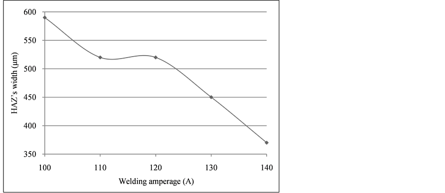
Figure 2. Estimated HAZ’s width for all welding amperages.

Figure 3. Microstructure transverse to the weld seam (140 A, 200 X).

Figure 4. The XRD spectra of some of the samples with bcc structure.

Figure 5. The XRD spectrum of the QS-sample. Mixed fcc & bcc.

Figure 6. Microstructure of welded 3.35-Si sample (200 X).

Figure 7. Microstructure of welded 3.75-Si sample (200 X).

Figure 8. Hardness profiles for various preheating temperatures (3.35-Si).

Figure 9. Estimated HAZ’s width for all preheating temperatures.

Figure 10. Hardness profiles for various welding amperages (3.75-Si).

Figure 11. Estimated HAZ’s width for all welding amperages.
・ At higher temperatures normalizing-type treatment resulted in higher hardness values. These values were formed according to the effect of RS.
・ After 900˚C at normalizing-type heat treatments the matrix ferrite was thermally affected.
・ A relatively normal hardness profile transversed to the seam with values fluctuating between 350 HV (DM) and 200 HV (matrix ferrite, BM).
・ Ferritic structures with HV values of 420 to 390 underlined thermally affected ferrite (HAZ).
・ This normal profile was abnormally disturbed by the presence of carbides at the partially melting zone of the weld (white iron, 900 - 1000 HV). They could not be manipulated without a proper pre- or post-weld heat treatment.
・ Inside the HAZ, the hardness changed progressively from the carbidic zone (900 - 1000 HV) to the unaffected ferrite zone (less than 280 - 260 HV).
・ HAZ stopped at the point where the HV values of the ferritic matrix dropped beyond the 280/260 threshold due to the presence of RS (unaffected ferrite).
・ The HAZ’s width was measured between this point and the point where carbides were present, just near the deposited metal area (partially melted zone).
・ It was strongly affected by the welding conditions. Higher currents (130, 140 Amps, base value the 90 Amps) for the 3.35-Si samples produced thinner HAZs.
5. Discussion
SMAW in general imposes crystallographic changes and RS in the ferritic matrix of the DI. They lead, both, in local increase of the mechanical strength of the material. Any local increase of the hardness, so, could be attributed to these two factors. Crystallographic changes are clearly defined by metallography. RS are practically invisible and could be detected only by indirect means. An abnormal increase, so, of the micro-hardness of the ferritic grains in the HAZ is directly related to RS. All our micro-hardness measurements are compatible to this model.
HAZ starts at the point where carbides are observed with very high HV values (more than 900 HV). This point belongs to the partially melted zone of the weld. From that point a characteristic zone with crystallographic modifications of the BM is observed. It incorporates RS also, but they cannot be clearly distinguished by optical microscopy.
By approaching the BM, beyond the previous referred zone, the hardness of the ferrite expresses higher than normal values. These values could be a strong evidence for the existence of thermally imposed RS.
By applying this model to our SMAW welds we focus our attention to the following:
・ Preheating results in absence of carbides for the 3.35-Si samples but in broadening of their HAZ’s width.
・ The Si content affects the HAZ’s width in a contradictory manner. For the 3.75-Si samples the lowest HAZ’s width is observed at 110 A. With increasing amperage the HAZ’s width broadens.
These notes could be explained by considering a substantial modification of the physical properties of the ferritic matrix due to the addition of Si. But the explanation of the data of Figure 9 and Figure 11 could not be directly related only on the percentage of Si. Further research based on the influence of the welding conditions on related materials seems to be necessary to be done.
Normalizing-type heat treatments of the as-cast samples at temperatures referred follow conditions closer to the ones of continuous cooling. They assist in distinguishing the thermally affected ferrite due to RS by micro- hardness measurements and measuring the HAZ’s width. All full annealing-type heat treatments left the matrix ferrite unaffected.
The model presents a low-cost procedure and is suitable for the industry (foundries) in order to evaluate welding conditions of this type (selection of welding electrodes etc) before doing more expensive mechanical tests.
These conclusions could assist, also, in the application of (NDT) XRD for characterizing of RS in high-Si ferritic DI grades SMAWs, especially where failures are observed [9] .
Acknowledgements
We express our thanks to:
・ Professor Georgios Litsardakis (Aristotle University of Thessaloniki, Faculty of Engineering, Laboratory of Materials for Electronics) for his kind contribution in performing the XRD spectra of our study.
・ Mr. Dimitrios Repanis MSc of “Hitiria Makedonias S.A.” for the preparation of the as-cast alloys.
・ Dr. Panagiotis K. Tsolakisof Materials Industrial Research & Technology Center―MIRTEC S.A. (Volos Industrial Area, Greece) for his kind contribution in performing the chemical analysis of the material with OES.
Cite this paper
Georgios K.Triantafyllidis,Dimitrios I.Zagliveris,Dionysios L.Kolioulis,Christos S.Tsiompanis,Titos N.Pasparakis,Athanasios P.Gredis,Melina L.Sfantou,Ioannis E.Giouvanakis, (2016) Residual Stresses and Micro-Hardness Testing in Evaluating the Heat Affected Zone’s Width of Ferritic Ductile Iron Arc Welds. Materials Sciences and Applications,07,73-82. doi: 10.4236/msa.2016.71007
References
- 1. Stefanescu, D.M. (1990) Classification and Basic Metallurgy of Cast Iron, Properties and Selection: Irons, Steels, and High-Performance Alloys. Vol. 1, ASM Handbook, ASM International, 3-11.
- 2. Davis, J.R. and Associates (1996) Cast Irons, Secondary Processing of Cast Irons, Welding and Brazing. ASM Specialty Handbook, 217-219.
- 3. Larker, R. (2009) Solution Strengthened Ferritic Ductile Iron ISO 1083/JS/500-10 Provides Superior Consistent Properties in Hydraulic Rotators. Overseas Foundry.
- 4. Repair and Maintenance Welding Handbook. 2nd Edition, ESAB.
- 5. (1995) The Metals Blue Book. Vol. 3, Welding Filler Metals, CASTI Publishing Inc. and American Welding Society.
- 6. Eagar, T.W. (1993) Energy Sources Used for Fusion Welding. ASM Handbook, Vol. 6, Welding, Brazing and Soldering, First Printing.
- 7. Fonda, R.W., Vandermeer, R.A. and Spanos, G. (1998) Continuous Cooling Transformation (CCT) Diagrams for Advanced Navy Welding Consumables. Naval Research Laboratory, United States Navy.
- 8. Krauss, G. (2007) Steels: Processing, Structure and Performance. 3rd Printing, ASM International.
- 9. Pineault, J., Manufacturing, P. and Mich, T. (2015) Measuring Residual Stresses via X-Ray Diffraction Helps Optimize Engine Component Fabrication. Advanced Materials and Processes, ASM International, 173, 20-22.
NOTES

*Corresponding author.