Materials Sciences and Applications
Vol.5 No.4(2014), Article ID:44379,8 pages DOI:10.4236/msa.2014.54027
Modeling of Orientation-Dependent Photoelastic Constants in Cubic Crystal System
Lubna Jahan Rashid Pinky1, Shakila Islam1, Md. Nur Kutubul Alam1, Mohammad Arif Hossain2, Md. Rafiqul Islam1
1Department of Electrical and Electronic Engineering, Khulna University of Engineering & Technology, Khulna, Bangladesh
2Department of Mathematics, Khulna University of Engineering & Technology, Khulna, Bangladesh
Email: islambit@yahoo.com
Copyright © 2014 by authors and Scientific Research Publishing Inc.
This work is licensed under the Creative Commons Attribution International License (CC BY).
http://creativecommons.org/licenses/by/4.0/


Received 3 January 2014; revised 5 February 2014; accepted 19 February 2014
ABSTRACT
Euler’s rotation theorem and tensor rotation technique are applied to develop a generalized mathematical model for determining photoelastic constants in arbitrary orientation of cubic crystal system. Two times rotations are utilized in the model relating to crystallographic coordinates with Cartesian coordinates. The symmetry of photoelastic constants is found to have strong dependence with rotation angle. Using the model, one can determine photoelastic constants in any orientation by selecting appropriate rotation angle. The outcome of this study helps to characterize spatial variation of residual strain in crystalline as well as polycrystalline materials having cubic structure using the experimental technique known as scanning infrared polariscope.
Keywords:Mathematical Modeling; Photoelastic Constants; Arbitrary Crystal Orientation; Euler’s Rotation Theorem; Tensor Rotation Technique

1. Introduction
The quality of semiconductor materials as well as devices is strongly dependent on residual strain induced in the materials during the growth and cooling processes [1] -[3] . Yamada et al. [4] [5] have developed computer controlled scanning infrared polariscope (SIRP) that is used to measure spatial distribution of strain in crystalline semiconductor wafers and ingot. Although SIRP can be effectively utilized for residual strain mapping in crystalline materials [6] [7] , it can not be applied to measure residual strain in polycrystalline materials, particularly, in solar cell materials [8] . The main problem is the photoelastic constants which are the key parameters required for SIRP measurements [6] [7] and have crystal direction/orientation dependence [9] . The photoelastic constants  and
and , and
, and  are measured by applying stress parallel to <100>, and <111> directions [10] [11] . To the best of our knowledge, there is no experimental measurement of photoelastic constants in arbitrary crystal direction.
It is well known that some mechanical and optical properties of semiconductor materials and devices strongly depend on crystal orientation [12] [13] . The polycrystalline Si-based solar cells exhibit poor efficiency that is speculated to be due to residual strain induced in the grain boundary as reported so far [8] . However, the quantitative amount of strain can not be measured due to lacking of orientation-dependent photoelastic constants of Si. Although Fukuzawa et al. [14] have reported spatial distribution of strain in polycrystalline Si using SIRP, determination of photoelastic constants in arbitrary crystal direction was not reported in details.
In this study, we for the first time propose a generalized mathematical model to determine photoelastic constant in arbitrary crystal orientation combining Euler’s rotation theorem and tensor rotation technique. Using the model one can calculate different components of photoelastic constants in cubic crystals just by choosing appropriate rotation angle. Herein the model is applied to determine the orientation-dependent photoelastic constants in Si crystal as an example. However, the model developed in the present study can be used to determine photoelastic constants in cubic/Zincblende crystal structure.
2. Proposed Model
The model is developed with the combination of Euler’s rotation theorem [15] and tensor rotation technique [9] . The rotation schematic is shown in Figure 1 where two times rotations are performed for the versatility of the model. At first X axis is rotated in XY plane by an angle  about the Z axis so that Y axis is rotated in -XY plane by the same angle. After the first rotation, the new position of X, Y, and Z are denoted by X¢, Y¢, and Z¢. Again, the X¢ axis is rotated in
  plane about the
  axis by an angle
 , as a result, the
  axis is also rotated in—X¢Z¢ plane by the same angle. The final position of X² and Z² is obtained after the second rotation. If Cartesian coordinate system relates to the conventional crystal coordinate system, the rotation angles j and
  of the general [hkl] direction relative to a crystal coordinate system fixed onto the [100], [010], and [001] directions can be given by the following relationships [16]
 (1)
(1)
 (2)
(2)
where the indices h, k, and l are the real integers for the case when the crystalline direction is specified in terms of the angles j and . We can determine the photoelastic constants in any crystal direction/orientation with the combination of the angles j and q.
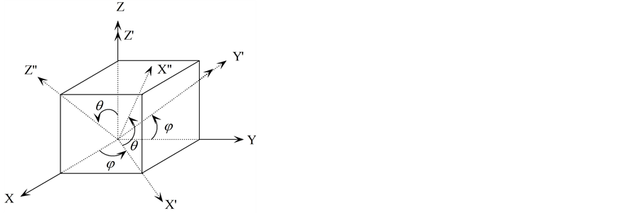
Figure 1. Rotation schematics applied in the proposed model.
3. Mathematical Analysis
At first, transformation of XY plane about Z axis by an angle j and then transformation of  plane about
  axis by an angle
  is applied according to the schematics shown in Figure 1. The rotation matrices obtained from the first and second rotations are represented by C and B, respectively, and indicated by Equations (3) and (4)
 (3)
(3)
 (4)
(4)
According to Euler’s rotation theorem, the combined rotation matrix M can be given [15] by
 (5)
(5)
The photoelastic constant,  , stress,
  , and change in refractive index,
  in semiconductor materials can be expressed by [9]
 (6)
(6)
Expansion of Equation (6) yields 81  components. Details are available in [9] . According to tensor rotation/transformation rule, symmetry transformation results in equivalent 36 components form the 81 components [9] -[11] . Employing an additional symmetry for the cubic system, only three independent components of photoelastic constants P11, P12, and P44 are existed [9] . The independent components along with other components are summarized in Table1 If photoelastic constant in any direction is known, its value in unknown direction can be determined using the following tensor rotation rule [9] ,
 (7)
(7)
where ,
,  ,
,  , and
, and  are the respective direction cosines between the two sets of coordinate axes before and after symmetry transformation in the case of Cartesian tensors which are expressed in the form of rotation matrix shown in Equation (5).
  is the value of known photoelastic constant and
  indicates the value which is to be evaluated. By expanding Equation (7) and considering the symmetry described in Table 1 [9] , the independent components of photoelastic constants in rotated direction can be expressed by

Table 1 . Equivalent components of Pijkl for cubic crystal system [9] .
 (8)
(8)
 (9)
(9)
 (10)
(10)
 (11)
(11)
 (12)
(12)
 (13)
(13)
 (14)
(14)
 (15)
(15)
 (16)
(16)
4. Orientation Dependent Photoelastic Constant
Using the mathematical formulations derived in Equations (8) to (16), we have calculated orientation-dependent photoelastic constants from [100] to [010], [110] to [001], and [100] to [001] directions with the combination of rotation angles j and q. The results are determined for the semiconductor Si using the known values of photoelastic constants listed in Table2
Figures 2(a)-(c) show a comparison among the photoelastic constants ,
,  , and
, and  which are determined for the rotation angles j = 0˚ to 90˚ and q = 0˚, j = 0˚ and q = 0˚ to 90˚, and j = 45˚ and q = 0˚ to 90˚, respectively. To compare their magnitudes, the figures are plotted in the same scale. The components
  and
and  are found symmetrical in Figure 2(a), but in Figure 2(b),
  and
and  are symmetrical and their values are maximum at 45˚ that is in the [110] direction. Apart from 45˚ they decrease following Gaussian profile and become equal to the known component P11 in the [100], [010], and [001] directions. It is also found in Figures 2(a) and (b) that the components
  and
and  are independent of the rotation angles and their values are equal to P11. The variations of the same components of photoelastic constants are shown in Figure 2(c) for the rotation from [110] to [001] direction. It is found that the components
  and
and  are symmetrical at [110] direction. In contrast,
  and
and  are symmetrical at [001] direction. Apart from these directions the cubic symmetry of these components has been lost due to the rotation. It is also found in Figure 2(c) that the component
  is independent of the rotation angle. On the other hand, the components
  and
and  vary nonlinearly and their magnitudes change oppositely from −0.0593 to −0.1053 due to the rotation.
Table 2. Experimental measurement of Photoelastic constants P11, P12, and P44 for Si crystal taken from Ref. [10] .
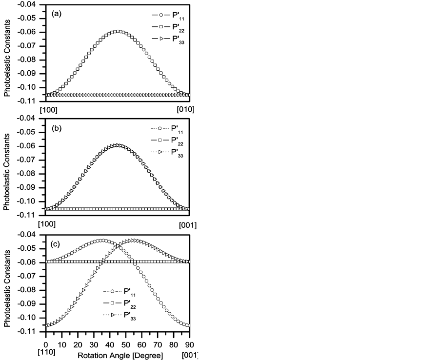
Figure 2. Variation of orientation-dependent photoelastic constants ,
,  , and
, and  plotted for the directions from (a) [100] to [010]; (b) [110] to [001]; (c) [100] to [001].
The variations of the photoelastic constants ,
,  ,
,  ,
,  ,
,  , and
, and  are shown in Figures 3(a)-(c) for the same rotation angles and directions as mentioned above. The curves are also presented in the same scale for making a comparison among them. It is found in Figure 3(a) that the components
 ,
,  ,
,  , and
, and  are symmetrical and their values are equal to the component P12. Similar results are found for the components
 ,
,  ,
,  , and
, and  in Figure 3(b). In contrast, the components
 ,
,  ,
,  , and
, and  vary symmetrically following Gaussian distribution similar to that shown in Figures 3(a) and (b). The maximum value is found −0.0323 for the components
  and
and , and
, and  and
and  in the directions [110] and [101], respectively. The direction dependent photoelastic constants
 ,
,  ,
,  ,
,  ,
,  , and
, and  is shown in Figure 3(c) where cubic symmetry in these components has been lost due to rotation, but the symmetry between
  and
and ,
,  and
and , and
, and  and
and  are found. The magnitudes of the components
  and
and , and
, and  and
and  vary from −0.0323 to 0.0137, and 0.0137 to −0.0323, respectively. As seen in Figure 3(c) that the profiles of the components
  and
and  follow Gaussian distribution and their magnitude is equal to 0.0137 in the directions [110] and [001]. The magnitude of these components is also found to be −0.0162 in the direction [111].
Figures 4(a)-(c) show a comparison among the orientation-dependent photoelastic constants ,
,  , and
, and  where their profiles are found identical for the rotation from [100] to [010] and [110] to [001] with respect to the profiles obtained from [110] to [001]. As seen in Figures 3(a) and (c), the cubic symmetry of these components has been lost due to the rotation from [100] to [010] and [110] to [001] directions. On the other
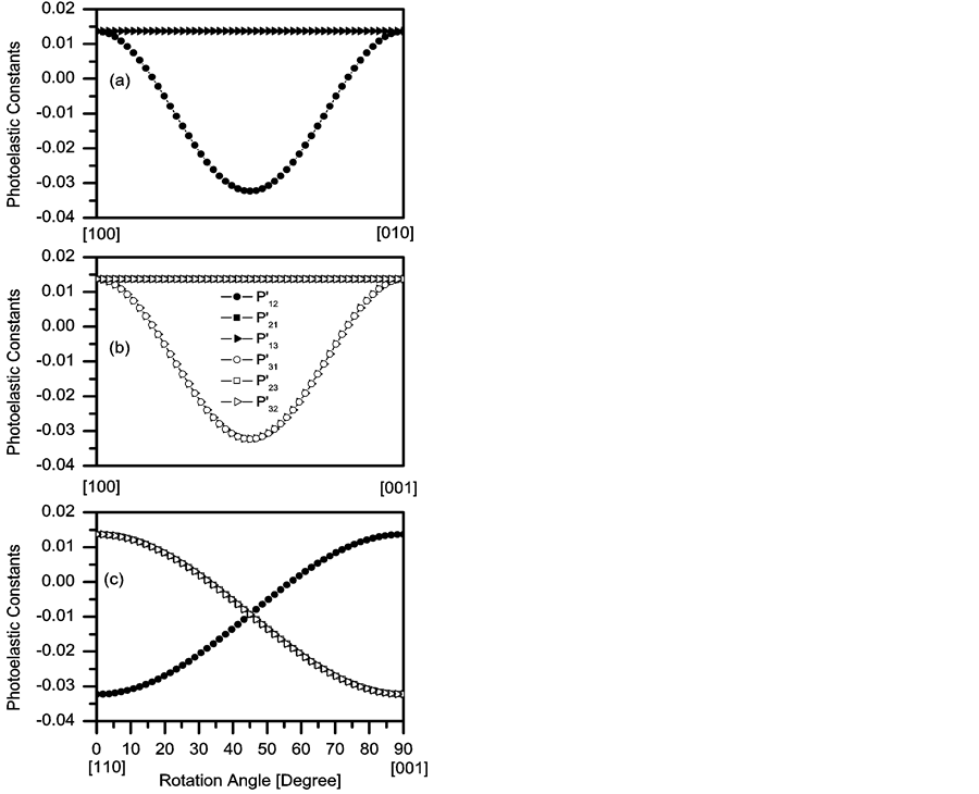
Figure 3. Variation of orientation-dependent photoelastic constants ,
,  ,
,  ,
,  ,
,  , and
, and  plotted for the directions from (a) [100] to [010]; (b) [110] to [001]; (c) [100] to [001]. The magnitude of the photoelastic constants
  =
= ,
,  =
= , and
, and  =
= .
.
hand, the component  is found asymmetrical with respect to the components
  and
and  in Figure 3(b). The magnitudes of
 ,
,  , and
, and  are equal to the known component P44 at [100], but their magnitudes are evaluated −0.073, −0.06615, and −0.027, respectively, at [110] direction. The components
  and
and  are evaluated −0.027 and
  is −0.073 at [101] direction. Further, their magnitudes are found to be very small at [010] and [001] directions. In Figure 3(c), the components
 ,
,  , and
, and  are estimated −0.073, −0.06615, and −0.027, respectively, at [110] direction. On the other hand, their values are evaluated −0.0428, −0.0361, and −0.0582, respectively, at [111] direction. Furthermore, the values of
 , and
, and  are estimated −0.027, and
  is −0.0203 at [001] direction.
5. Conclusion
A generalized mathematical model is developed for cubic crystal system to determine photoelastic constants in arbitrary orientation with the combination of tensor rotation technique and Euler’s rotation theorem. Three independent components of photoelastic constants become nine independent components due to two times rotations. However, some of them are found symmetrical depending on the rotation direction. The magnitude and variation pattern of the photoelastic constants are also found to have direction-dependent. But, for a particular
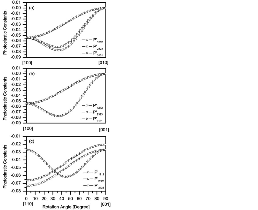
Figure 4. Variation of orientation-dependent photoelastic constants ,
,  , and
, and  plotted for the directions from (a) [100] to [010], (b) [110] to [001], and (c) [100] to [001].
direction, some components are found independent of rotation angle. Here, the model is applied for silicon crystal as an example. It can be applied for any crystal having cubic/Zincblende structure.
References
- Yamada, M. (1993) Relief of Residual Strains in Gallium Phosphide (100) Wafers by Cracking. Journal of Applied Physics, 74, 6435. http://dx.doi.org/10.1063/1.355125
- Islam, M.R., Verma, P., Yamada, M., Kodama, S., Hanaue, Y. and Kinoshita K. (2002) The Influence of Residual Strain on Raman Scattering in InxGa1-xAs Single Crystals. Materials Science and Engineering: B, 91-92, 66-69. http://dx.doi.org/10.1016/S0921-5107(01)00972-2
- Miao, Z.L., Yu, T.J., Xu, F.J., Song, J., Lu, L., Huang, C.C., Yang, Z.J., Wang, X.Q., Zhang, G.Y., Zhang, X.P., Yu, D.P. and Shen, B. (1994) Dependence of Optical Gain on Crystal Orientation in Surface-Emitting Lasers with Strained Quantum Wells. Applied Physics Letters, 65, 1886. http://dx.doi.org/10.1063/1.112878
- Yamada, M. (1993) High-Sensitivity Computer-Controlled Infrared Polariscope. Review of Scientific Instruments, 64, 1815. http://dx.doi.org/10.1063/1.1144016
- Chu, T., Yamada, M., Donecker, J., Rossberg, M., Alex, V. and Riemannb H. (2003) Optical Anisotropy in Dislocation-Free Silicon Single Crystals. Microelectronic Engineering, 66, 327-332. http://dx.doi.org/10.1016/S0167-9317(02)00935-8
- Hermsm, M., Fukuzawa, M., Melov, V.G., Schreiber, J., Mock, P. and Yamada, M. (2000) Residual Strain in Annealed GaAs Single-Crystal Wafers as Determined by Scanning Infrared Polariscopy, X-Ray Diffraction and Topography. Journal of Crystal Growth, 210, 172-176. http://dx.doi.org/10.1016/S0022-0248(99)00673-9
- Fukuzawa, M. and Yamada, M. (1996) Fine Structures of Residual Strain Distribution in Fe-Doped lnP-100) Wafers Grown by the LEC and VCZ Methods. Journal of Electronic Materials, 25, 337-342. http://dx.doi.org/10.1007/BF02666598
- Chen, J., Chen, B., Sekiguchi, T., Fukuzawa, M. and Yamada, M. (2008) Correlation between Residual Strain and Electrically Active Grain Boundaries in Multicrystalline Silicon. Applied Physics Letters, 93, 112105. http://dx.doi.org/10.1063/1.2983649
- Narasimhamutry, T.S. (1981) Photoelastic and Electro-Optic Properties of Crystals. Plenum Press, New York. http://dx.doi.org/10.1007/978-1-4757-0025-1
- Biegelsen, D.K. (1974) Physical Review Letters, 32, 1196.
- Levine, Z.H., Zhong, H., Wei, S., Allan, D.C. and Wilkins, J.W. (1992) Strained Silicon: A Dielectric-Response Calculation. Physical Review B, 45, 4131. http://dx.doi.org/10.1103/PhysRevB.45.4131
- Hasan, M.M., Islam, M.R. and Teramoto, K. (2012) Crystallographic Orientation-Dependent Optical Properties of GaInSb Mid-Infrared Quantum Well Laser. Optik—International Journal for Light and Electron Optics, 123, 1993-1997. http://dx.doi.org/10.1016/j.ijleo.2011.09.021
- Zwinge, G., Wehmann, H.-H., Schlachetzki, A. and Hsu C.C. (1993) Orientation-Dependent Growth of InGaAs/InP for Applications in Laser-Diode Arrays. Journal of Applied Physics, 74, 5516. http://dx.doi.org/10.1063/1.354208
- Fukuzawa, M., Yamada, M., Islam, M.R., Chen, J. and Sekiguchi, T. (2012) Quantitative Photoelastic Characterization of Residual Strains in Grains of Multicrystalline Silicon. Journal of Electronic Materials, 39, 700-703. http://dx.doi.org/10.1007/s11664-010-1164-x
- http://mathword.wolfram.com/Euler Angles.html
- Okuno, Y., Uomi, K., Aoki, M. and Tsuchiya, T. (1997) Direct Wafer Bonding of III-V Compound Semiconductors for Free-Material and Free-Orientation Integration. IEEE Journal of Quantum Electronics, 33, 959-969. http://dx.doi.org/10.1109/3.585484