Materials Sciences and Applications
Vol. 4 No. 1 (2013) , Article ID: 27075 , 11 pages DOI:10.4236/msa.2013.41007
Synthesis and Characterization of Mesostructured Cellular Foam (MCF) Silica Loaded with Nickel Nanoparticles as a Novel Catalyst
![]()
1School of Chemical Engineering, Universiti Sains Malaysia, Penang, Malaysia; 2Department of Chemical Engineering, Universitas Lampung, Lampung, Indonesia.
Email: *chzuhairi@eng.usm.my
Received October 5th, 2012; revised October 25th, 2012; accepted November 23rd, 2012
Keywords: Mesostructured Cellular Foam; Amorphous Materials; Nanostructures; Sol-Gel Growth; Surface Properties
ABSTRACT
This work investigated the possibility of incorporation of nickel into several mesostructured cellular foam (MCF) silica supports prepared at various aging times (1, 2, and 3 days) by using deposition-precipitation method followed by reducetion process and to look for the best support to obtain supported nickel catalyst with highest nickel loading and smallest size of nickel nanoparticles. Analyses using nitrogen adsorption-desorption, transmission electron microscopy (TEM), X-ray diffraction (XRD), scanning electron microscopy (SEM) and energy dispersive X-ray (EDX) showed that MCF silica prepared at aging time of 3 days was the best support as the corresponding nickel functionalized MCF catalyst had the highest nickel content (17.57 wt%) and the smallest size of nickel nanoparticles (1 - 2 nm) together with high porosity (window pore size of 90 Å). The result was attributed to the highest window pore size in the MCF support which allowed more nickel nanoparticles to be incorporated.
1. Introduction
Supported nickel catalysts as heterogeneous catalysts have attracted research attentions because of their potential application in many important petrochemical industries such as hydrogenation, deoxygenation, methanation, reforming, and hydrocracking. Besides good nickel particle dispersion in the catalyst support, pore size is a crucial variable affecting the catalyst performance as the activity usually relies on the presence of accessible active centres located in the internal pore of the catalysts [1]. Larger-pore sizes of the catalyst provide better diffusion of reactants and products during the course of reaction [2]. Therefore, high dispersion of small particles of nickel and high porosity of the catalyst are always desirable. Catalyst support may play a more active role in increasing the dispersion and stability of metal particles [3]. The main function of catalyst support is to achieve a fine dispersion of nickel nanoparticles and to prevent the nanoparticles from aggregating and the latter relies on confining nanosized environment of the catalyst [4].
Mesoporous silica materials such as MCM-41, SBA- 15 and HMS with high porosity (pore size of up to 100 Å) have been widely studied as catalyst supports for incurporation of sulphated metal oxides [5,6], platinum nanoparticles [7] and propyl sulfonic acid [8-10]. These mesoporous silica materials have also been extensively used as supports for incorporation of nickel particles. Nickel functionalized mesoporous silicas have been successfully applied for hydrochorination of chlorobenzene [11] and catalytic reforming of methane with carbondioxide to produce synthesis gas (syngas) [12,13]. By using direct synthesis [2,12], post synthesis-grafting and impregnation methods [13] for incorporation of nickel, mesoporous silica materials (MCM-41, SBA-15, HMS) would form catalysts with good dispersion of nickel particles at nickel contents below 6 wt%. However, higher nickel loadings could lead to structural collapse and a significant drop in the well-defined framework mesoporosity because of local blockage of pore cannel and agglomeration of nickel nanoparticles. This could result in diffusion limitation of reactants as well as the products to consequently reduce the activity of the catalyst. Recently, MCM-41 was incorporated with nickel particles using deposition-precipitation method followed by a reduction process that resulted in catalyst with good nickel particles dispersion at high nickel loading of 12.8 wt% [14]. However, the supported MCM-41 nickel catalyst had low porosity (average pore diameter of 39 Å) that would not be suitable for reactions involving bulky molecules such as hydrogenation of edible or non edible oil and deoxygenation of fatty acid. These reactions require catalysts with pore diameters of above 50 Å to diminish diffusion limitation of reactants and products [15]. Besides that, catalysts derived from MCM-41 support faced serious drawback of low hydrothermal stability [16-18].
Mesostructured cellular foam (MCF) silica is a very interesting new mesoporous silica material. It is a class of three-dimensional (3D) materials with ultra-large mesopores (up to 500 Å) that are hydrothermally robust [19-22]. In terms of the textural and framework structures, MCF materials are composed of uniform spherical cells interconnected by window pores with a narrow size distribution [19]. Owing to their 3D mesopore system with pore sizes substantially larger than those of MCM- 41 or SBA-15 or HMS mesostructures, this material seems to be a very promising candidate to be used as catalytic support as it provides a better diffusion of reactants and products. This allows them to better overcome mass transfer limitations in many reactions [20,23]. However, there has been limited information about the utilization of MCF silicas as supports for loading of catalytically active component. Also, report addressing the dispersion of nickel particle on mesostructured cellular foam (MCF) silica is hardly found in the literature so far.
In the present study, MCF silica materials with differrent mesostructure characteristics have been prepared at various aging times (1, 2 and 3 days) and used as supports for nickel incorporation. The incorporation of nickel particle in the MCF silica has been carried out using deposition and precipitation (DP) method followed by a reduction process. The aims of this study are to investigate the influence of MCF support characteristics on surface and structural characteristics of nickel functionalized MCF catalysts. Thus, the best MCF support can be identified in order to obtain a catalyst with highest content of nickel nanoparticles together with high porosity. MCF silica supports and the corresponding nickel functionalized MCF catalysts have been characterized using nitrogen adsorption-desorption, TEM, SEM-EDX and XRD analyses.
2. Experimental Procedure
2.1. Synthesis of MCF Supports
MCF silica materials with different structures were synthesized according to a previously reported procedure [24] with modification with regards to the amount of acidic solution, the use of aging temperature and aging times. In a typical synthesis, 4 g of Pluronics 123 was dissolved in 70 ml of 1.6 M HCl. Then, 6.8 ml of trimethylbenzene (TMB) was added, and the resulting solution was heated to 40˚C with rapid stirring to synthesize the microemulsion (template). After stirring for 2 h, 9.2 ml of tetraethyl orthosilicate (TEOS) was added to the solution and stirred for 5 min. Then, the solution was transferred to a poly-ethylene bottle and kept at 40˚C in an oven for 20 h for the formation of pre-condensed silica foam. After that, the mixture was removed from the oven and then NH4F·HF solution (92 mg in 10 ml DI water) was added to the mixture under slow mixing. Then, the mixture was aged at 80˚C in an oven for certain aging times. Three samples prepared using the synthesis procedure were MCF-1D that was aged for 1 day, MCF-2D that was aged for 2 days and MCF-3D that was aged for 3 days. After cooling, the mixture was filtered and the collected solid was then dried at 100˚C for 12 h. After that, calcination was carried out in static air at 300˚C for 0.5 h and 500˚C for 6 h to remove the template. The calcined MCF silica materials were used as supports for Ni incorporation.
2.2. Nickel Incorporation into MCF Supports
MCF-1D, MCF-2D and MCF-3D materials were then functionalized with nickel using a deposition-precipitation method adopted from Nares et al. [14]. In the functionalization reaction, 250 ml of an nickel nitrate solution was prepared by dissolving 10.156 g of Ni(NO3)2·6H2O and 0.3 ml of HNO3 (69%wt/wt) with distilled deionize water. Then, 40 ml of the nickel nitrate solution was used for dissolving 6.3 g urea at room temperature to produce a urea solution and 210 ml of the nickel nitrate solution was mixed with 1.9 g of MCF silica materials to make a suspension. The suspension was then heated at 40˚C during which the urea solution was added under rapid mixing. After that, the mixture was heated to 90˚C for 2 h under static condition. After cooling, the mixture was filtered and the collected solid was washed three times with 20 ml hot distilled water (~50˚C) and then dried at 100˚C for 12 h. The solid was subsequently calcined in static air at 300˚C for 6 h. The calcined solids are designnated as NiMCF-1D(C), NiMCF-2D(C) and NiMCF- 3D(C). The samples were then reduced at 550˚C for 2.5 h under hydrogen stream and subsequently cooled to room temperature under nitrogen flow. The reduced samples are designated as NiMCF-1D(R), NiMCF-2D(R) and NiMCF-3D(R).
2.3. Characterization of Nickel Loaded MCF
Nitrogen adsorption-desorption isotherms were obtained using a Quanta-chrome Autosorb 1C automated gas sorption analyzer at liquid nitrogen temperature. Prior to the experiments, the samples were degassed (p < 10−1 Pa) at 270˚C for 6 h. The amounts of nitrogen gas adsorbed over a range of partial pressures were measured to obtain a graph known as an adsorption isotherm, whilst desorption isotherm was obtained by measuring the quantities of nitrogen desorbed from the sample as the relative pressure was gradually lowered. Specific surface area (SBET) was calculated using the BET method, while pore size distribution was obtained using the Barrett-JoynerHalenda (BJH) model applied to the adsorption and desorption isotherms data.
The samples were also used for SEM/EDX imaging using a Leo Supra 50 VP field emission SEM, equipped with an Oxford INCAX act, which was an energy dispersive X-ray microanalysis system. Prior to analysis, samples were mounted on stubs with double-sided adhesive tape. Then, the samples were coated with high purity gold and observed at room temperature.
TEM images were obtained by means of a Philips CM 12 transmission electron microscope. About 0.08 g of each sample was first dissolved in 5 ml of 100% ethanol. The solution was then shaken for a moment and subsequently a small amount of the solution was taken using a micropipette and dropped on a metal grid for the analysis.
X-ray diffraction (XRD) analysis was performed using a Siemens 2000 X system to obtain XRD patterns of the catalysts at different stages of synthesis in order to identify the different phases in the materials. The observation was made on the calcined and reduced catalyst samples. The diffraction patterns were recorded using Cu-Kα radiation at 2θ angles ranging from 10˚ - 100˚.
3. Results and Discussion
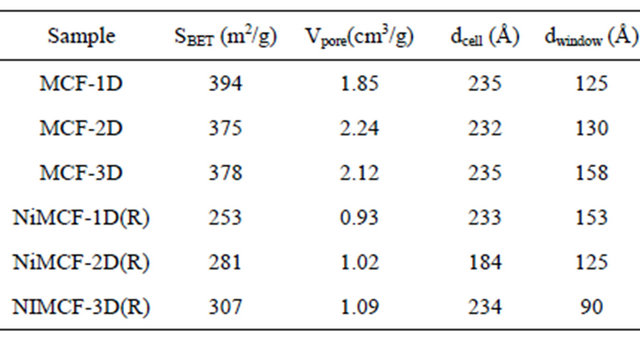
Table 1 summarizes textural properties of various MCF silica supports prepared at different aging times as well as those of the corresponding nickel functionalized MFC catalysts after the reduction process. The textural properties were derived based on nitrogen adsorption-desorption data using Barrett, Joyner and Halenda (BJH) method to obtain the average cell size (dcell) and window pore size (dwindow pore). Specific surface area (SBET) was evaluated using Brunauer, Emmett and Teller (BET) method. Meanwhile, total pore volume (Vpore, cm3/g) was calculated as the amount of nitrogen adsorbed at P/P0 = 0.9948. The window pore size in MCF silica supports increased with increasing aging time whilst cell size remained stable, as suggested by data in Table 1. This result could be attributed to the “soft silica”-coated TMB/ P123 microemulsion droplets (composite droplets) that experienced an increase in size and consequently expanded the window pore size in the composite droplets during the aging step at 80˚C. At the same time, condensation of silica in the walls took place with the formation of Si-O-Si linkages to solidify the inorganic network, and subsequently the materials with increased pore size gradually rigidified [25,26]. As longer duration of aging was allowed, the larger window pore size in MCF structure would be obtained. The highest window pore size (158 Å) was achieved with an aging time of 3 days in the synthesis of MCF supports. The increase in window pore size with the increase in aging time in the synthesis of MCF silica materials was also observed by the other researchers who studied the effects of acid concentration and aging time in preparation of MCF used for adsorption of biomolecules [27].
Table 1 also shows that the total surface area of MCF silica support slightly decreased from 394 to 375 cm2/g when the aging time was increased from 1 day to 2 days. The reduction in the BET surface areas with increasing aging time might be ascribed to the enlargement of window pore sizes and the formation of denser framework walls [25,26]. However, the total surface area slightly increased from 375 to 378 cm2/g if the aging time was increased from 2 days to 3 days. The increase in aging time from 1 day to 2 days resulted in an increase in total pore volume from 1.85 to 2.24 cm3/g. Further increase in aging time to 3 days caused a slight decrease of the total pore volume to 2.12 cm3/g.
Incorporation of nickel into MCF silica supports resulted in some changes in textural parameters such as total surface area, total pore volume, cell size and window pore size as can be seen in Table 1. The incorporation of nickel into MCF silica support was carried out using deposition-precipitation method at 90˚C for 2 h. The solid sample was then collected, dried at 100˚C, calcined at 300˚C and finally reduced at 550˚C. Depositionprecipitation method generally involves the conversion of a highly soluble metal precursor into another substance which specifically precipitates onto a support and not in solution [28]. In this study, silica (from MCF material) was suspended into the solution containing nickel nitrate salt, urea and nitric acid at room temperature. Deposition-precipitation was started when the temperature of the suspension reached 90˚C. This condition led to urea hydrolysis (Equation (1)) that resulted in the for-
Table 1. Nitrogen adsorption-desorption result of MCF silica supports and the corresponding nickel funtionalized nickel MCF catalysts.
mation OH− and a gradual increase in pH [29]. The function of nitric acid was to better regulate the changes in pH by neutralizing the released OH− ion so that the suspension pH was maintained. It was suggested in the literature that the released OH− ions also hydrolyzed the nickel hexa-aqua complex ([Ni(OH2)6]2+) in the suspendsion to generate nickel hydroxoaqua complexes [29] as given in Equation (2).
 (1)
(1)
Furthermore, mechanism of nickel incorporation into silica derived from porous silicas Spherosil with high surface area i.e. SBET = 356 m2/g (Rhone-Poulenc, France, purity > 99.5%, XOA400) using the deposition-precipitation method has been proposed in the literature [30] and it is assumed to be analogues to nickel incorporation into MCF silica in this study. The mechanism can be briefly explained as follows: As the pH in the suspension was increased, silica derived from MCF support became negatively charged and the pH was higher than its point of zero charge (PZD ~pH 2). As such MCF silica would electrostatically adsorbed the nickel hexa-aqua ([Ni(OH2)6]2+) which was in equilibrium with nickel(II) hydroxoaqua complexes of [Ni(OH)(OH2)5]+ and Ni(OH)2(OH2)4 as given in Equation (2). As the Ni(OH)2(OH2)4 complex approached to the surface of MCF silica, it reacted with silanol groups (Si-OH) in MCF silica via hydrolytic adsorption which is an heterocondensation reaction. Then, it further reacted with the another Ni(OH)2(OH2)4 complex to form nickel phylosilicate layer on MCF silica via olation reaction which is formation of a hydroxo bridge between two metal centres as can be seen in Figure 1.
It has been reported in the literature that the basic medium could also cause partial silica dissolution as OH− ions which are catalysts for silica depolymerisation [31], as can be seen in Figure 2. The silica dissolution also released  ions that were further hydrolyzed to silicic acid (Si(OH)4). Furthermore, the silicic acid can react with Ni(OH)2(OH2)4 complex in the suspension via a heterocondensation reaction to form Si-O-Ni monomers as proposed in the literature [30]. These monomers can polymerize and grow on the surface of MCF silica leading to the formation of nickel phylosilicate on its surface. After the deposition-precipitation stage, the sample was dried at 100˚C for 12 h and then calcined at 300˚C for 6 h in order to eliminate water more efficiently before the reduction step. No decomposition of nickel phylosilicate on MCF silica could occur during the drying step at 100˚C and subsequently in the calcinations step at 300˚C as suggested in the literature [32]. Decomposition of the nickel phylosilicate into NiO on silica only occurred when the calcination temperature exceed 300˚C until 600˚C. It was reported in the literature that with more efficient elimination of water from the sample, smaller size metal nanoparticles on the silica can be produced after the reduction process [33].
Figure 3 schematically shows the mechanism of nickel nanoparticles formation during the reduction process which was adopted from Buratin et al. [30,32]. There were two steps in the mechanism of nickel particles formations that can be proposed i.e. the decomposition step and the reduction step. When the calcined samples i.e. NiMCF-1D(C), NiMCF-2D(C) and NiMCF-3D(C) were heated at 550˚C under hydrogen stream for 2.5 h, nickel phylosilicate in the calcined samples would be decomposed to NiO and silicate. Then, NiO would be reduced to Ni nanoparticles.
From the mechanisms of deposition-precipitation, MCF silica dissolution and formation of nickel particles that have been elucidated above, it can be concluded the changes in the textural parameters after the incorporation of nickel into MCF silica supports were affected by the partial dissolution of siliceous pore walls occurring during deposition-precipitation and by the deposition of nickel particles. Similar behaviour was also observed by Nares et al. [14] who used MCM-41 as the silica support. Table 1 shows that after the nickel incorporations, textural parameters of MCF silica supports generally decreased most probably due to the deposition of nickel on pore walls or on the surface of the MCF silica supports. However, for MCF-1D support prepared at an aging time of 1 day, window pore size increased from 125 Å to 153 Å after the incorporation of nickel. This behaviour was most likely due to a greater consumption of the siliceous pore walls during the deposition-precipitation.
MCF silica materials are made up of spherical cells interconnected by window pores in which the window pores are gates for accommodating active sites in the spherical cells. The reduction of total pore volume of MCF silica supports after the functionalization can be confirmed on the basis of the pore size distribution curves which include the size distributions of cells and window pores. The size distributions of cells in the samples were evaluated using the BJH method from the adsorption branch of the isotherm of the sample. Meanwhile, the size distributions of cells window pores of a sample were evaluated using BJH method from the desorption branch.
The size distributions of window pores of MCF silica

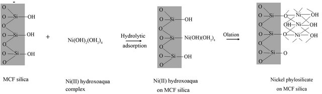
Figure 1. Mechanism of deposition-preposition adopted from Burattin et al. [29].
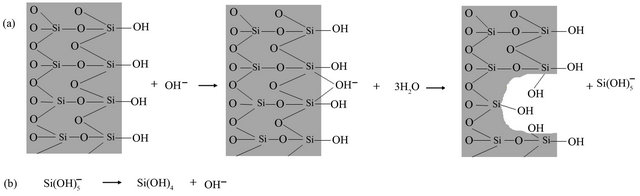
Figure 2. Mechanism of silica dissolution in MCF material adopted from Burattin et al. [29].

Figure 3. Mechanism of reduction process at 550˚C for 2.5 h under H2 stream adopted from Burattin et al. [31,32].
materials and nickel functionalized MCF materials are shown in Figure 4. The figure provides strong evidences of pore volume reductions in which cell and window pore size distribution curves in nickel species functionalized MCF materials (NiMCF-1D(R), NiMCF-3D(R), and NiMCF-3D(R)) were smaller compared to those in MCF materials. Furthermore, functionalization of MCF-1D resulted in a bimodal window pore size distribution with maximum peaks occurring at around 30 Å and 150 Å. The maximum peak in window pore size distribution of MCF-1D parent material was at around 150 Å.
Meanwhile, the maximum peak of cell size distribution (at about 230 Å) in MCF-1D did not change after the functionalization. Functionalization of MCF-2D resulted in a decrease in the maximum peak of cell size distribution from about 230 to 200 Å. However, the maximum peak of window pore size distribution (at about 130 Å) in MCF-2D was about the same as that in the nickel functionalized MCF-2D material. Different observation was made for MCF-3D material, in which the maximum peak in window pore size distribution was much lower after the functionalization with nickel. The reductions of pore volume, cell and window pore sizes were attributed to the attachment of nickel nanoparticles to the pore surface. The similar results have been reported for MCF silica materials that were successfully loaded with other active sites such as vanadium, vanadium oxide, lithium, polyethyleneimine and chromium [34-38].
Nitrogen adsorption-desorption isotherms for MCF silica materials shown in Figure 5 suggest that they are of type IV hysteresis that occurs in multilayer range of physisorption isotherms. This hysteresis is often associated with capillary condensation (the pore filling process) in mesopore structure [39]. The nitrogen adsorption-desorption isotherms are in close agreement with those published previously [19,20,25,26] and exhibit a large H1 hysteresis loop, which suggests that the MCF materials possessed cell-type mesopores connected by smaller window pores. According to IUPAC (International Union of Pure and Applied Chemistry) recommendation, pores with diameter not exceeding 20 Å are defined as micropores, while mesopores are pores with diameter between 20 and 500 Å. Meanwhile, macropores represent pores with diameter greater than 500 Å [39]. Type IV adsorption isotherms usually flatten at high P/Po indicating that the mesopore filling is complete [40]. However, final upward turn was observed for all the isotherm curves as shown in Figure 5. This was due to capillary condensation in macropores or in interstices between grains as reported in the literature [41].
Surface functionalization of MCF silica materials with nickel followed by a reduction process in hydrogen flow at 550˚C resulted in NiMCF-1D(R), NiMCF-2D(R), NiMCF-3D(R) catalysts with lower isotherm curves but no appreciable change in the form of the isotherm was observed (Figure 5). This observation indicated that total pore volume experienced a decrease but the mesoporosity of the MCF materials was maintained after functionalization. This result was comparable with that reported by Na-Chiangmay et al. [42] who observed that functionalization of MCF material with Pd had no significant influence on the structure of mesoporous support material. Furthermore, it was noted that, the incorporation of nickel into MCF-3D material resulted in the highest adsorption in NiMCF-3D(R) as compared to those in NiMCF-1D(R) and NiMCF-2D(R). The result suggested the lowest densification of the silica walls in NiMCF- 3D(R).
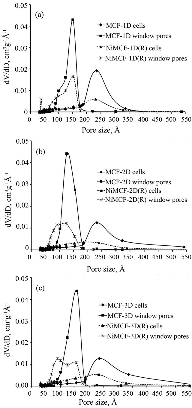
Figure 4. Cell and window pore size distribution of (a) MCF -1D and NiMCF-1D(R), (b) MCF-2D and NiMCF-2D(R), (c) MCF-3D and NiMCF-3D(R).
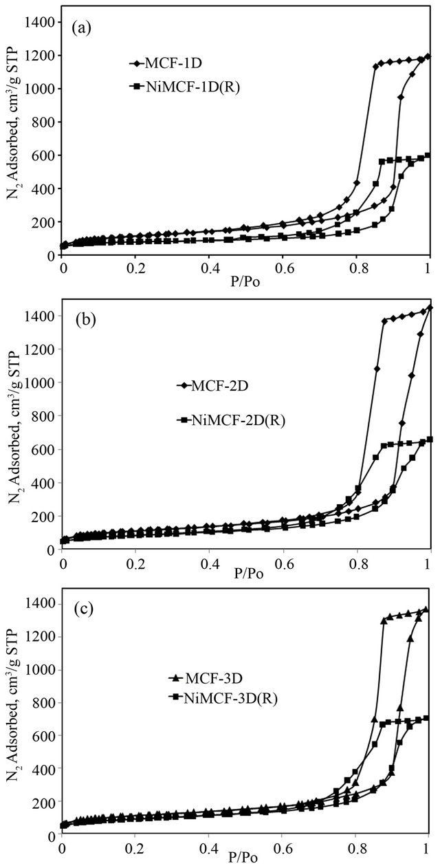
Figure 5. Nitrogen adsorption-desorption isotherm of (a) MCF-1D and NiMCF-1D(R), (b) MCF-2D and NiMCF- 2D(R), (c) MCF-3D and NiMCF-3D(R).
Figure 6(a) shows the scanning electron microscope (SEM) image of MCF-3D material that clearly confirmed a spherical particle of MCF-3D with a size of about 5 μm in diameter. A higher magnification SEM image (Figure 6(b)), and transmission electron microscope (TEM) image (Figure 6(c)) show that MCF-3D possessed a mesoporous structure with cell size of about 240.5 Å (24.05 nm). This result was consistent with the average cell size (235 Å) obtained from nitrogen adsorption-desorption data (Table 1). The TEM image also confirmed a disordered array of silica struts that are composed of uniform-sized spherical cells interconnected by window pores with a narrow size distribution which is the characteristic structural feature of MCF material [19,26]. It has been reported in the literature that schematic cross section of MCF material is of strutlike structure. Figure 6(d) clearly shows that the cells of the MCF structure were framed by the silica struts [26]. The wall thickness of the MCFs estimated through TEM analysis was about 5 nm. This result was in agreement with the thick, robust framework walls as observed in MCF-type mesoporous silica [26].
Morphology of various MCF silica materials (MCF- 1D, MCF-2D and MCF-3D) which were incorporated with nickel using deposition-precipitation method, followed by reduction process was examined by means of SEM while the chemical composition was determined using EDX. The results are shown in Figure 7 and they indicate that morphology and chemical composition of the nickel incorporated MCF catalysts were strongly influenced by the characteristics of supports i.e. MCF silica materials. Nickel nanoparticles in the form of nanoworms dispersed in NiMCF-1D(R) catalyst prepared using MCF support with an aging time of 1 day had larger sizes compared to those in NiMCF-2D(R) and NiMCF-3D(R) catalysts prepared using MCF support with aging times of 2 and 3 days, respectively.
The SEM analysis results also show that all nickel func tionalized MCF catalysts synthesized in this study still had highly porous structures. These results were in agreement with results from nitrogen adsorption-desorption isotherms curves in Figure 5 which indicated the mesoporosity of all resulted nickel functionalized MCF catalysts. Besides that, SEM analysis results in Figure 7 was also in agreement with results from Table 1 confirming that all nickel functionalized MCF catalysts had average window pore sizes of above 50 Å. These sizes made them suitable for the application in reactions involving bulky molecules [15]. This is because the window pores are gates for reactants or products access to the cell where the active centres were mostly located in the catalysts derived from MCF silica material [27].
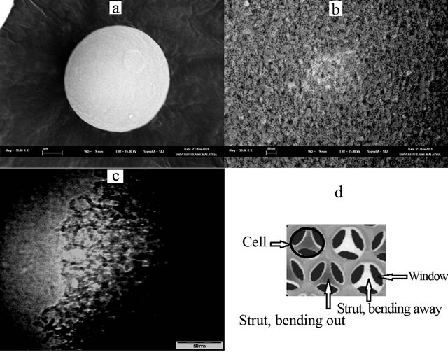
Figure 6. (a) SEM image of MFC-3D showing its morphology; (b) A higher magnification image showing the morphology of the MCF-3D surface; (c) TEM image of MCF-3D (d) Schematic cross section of MCF material [26].
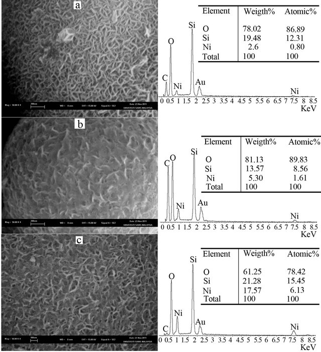
Figure 7. SEM images (left) together with chemical compositions (right) of (a) NiMCF-1D(R), (b) NiMCF-2D(R) and (c) NiMCF-3D(R).
Furthermore, it is observed from SEM images in Figure 7 that NiMCF-1D(R) catalyst had the highest porous structure as shown in Figure 7. The second highest porous structure was the NiMCF-3D(R) catalyst. Whereas NiMCF-1D(R) had the highest porous structure, it con tained the lowest amount of nickel composition i.e. 2.6 wt%. Meanwhile, the highest amount of nickel incorporation was in the NiMCF-3D(R) catalyst i.e. 17.57 wt%. The amount of nickel nanoparticles dispersed in the MCF materials in this study decreased in the order of NiMCF- 3D(R) > NiMCF-2D(R) > NiMCF-1D(R).
The amount of nickel composition in NiMCF-3D(R) catalyst in this study was higher than that in nickel functionalized HMS, SBA-15 or MCM-41 catalyst as reported in the literature [11-13]. The maximum amounts of nickel composition that were incorporated into the HMS and SBA-15 materials were only about 6 wt% and 5 wt%, respectively. Higher loadings of nickel detrimental to the mesostructure of the catalyst [11]. Meanwhile, nickel functionalized MCM-41 reaching a nickel composition of 12.8 wt% with an average nickel nanoparticles size of 3.38 nm has been reported in the literature [14]. However, synthesized nickel functionalized MCM-41 had an average pore diameter of 40 Å which could have limitation in reactions involving bulky molecules. Besides that, nickel supported mesoporous catalysts derived from MCM-41 materials had lower hydrothermal stability [16-18].
It was envisioned that window pore size of MCF material used as a support was the main factor that influenced the nickel nanoparticle incorporation. The window pore size of MCF support prepared using an aging time of 3 days (MCF-3D) was the highest among the others and window pore size of MCF-2D was higher than that of MCF-1D, as presented in Table 1. As such, most of nickel nanoparticles were easily introduced through the window pore size of MCF-3D support. This resulted in the highest amount of nickel nanoparticles in the NiMCF-3D(R). It can be concluded in this study that larger window pore size of MCF support resulted in the easier incorporation of nickel nanoparticle with smaller sizes. Hence, a suitable support was necessary for obtaining a high dispersion of nickel species with small size and high porous structure. This result was consistent with that reported by Subagyono et al. [43] who incorporated polyethyleneimine (PEI) into MCF silica material that was used as adsorbent for CO2. They observed that the larger window pores in MCF material allowed more PEI to be incorporated.
The dispersion of nickel nanoparticles in MCF silica supports was further determined through TEM analysis and the results are shown in Figure 8. In general, it is noted that nickel nanoparticles (dark spots) were successfully dispersed on the support and no bulk particles (size of above 10 nm) were observed. This result indicated that drying at 100˚C for h and calcinations at 300˚C for 3 h attempted this study were efficient enough to remove water from the catalysts before the reduction step to consequently result in small nickel nanoparticles dispersed in the catalysts as suggested in the literature [33].
It can also be noted that, for the NiMCF-3D (R) prepared using MCF support prepared at an aging time of 3 days, a narrow nickel particle size distribution and small nickel particles with a mean particle size about 1 - 2 nm were observed. The mean nickel nanoparticle size in NiMCF-3D(R) in this study was smaller compared to that in NiMCM-40 as reported by Nares et al. [14]. The NiMCM-40 catalyst contained 13 wt% of nickel particles with a mean size of 3.38 nm. However, for NiMCF- 1D(R) and NiMCF-2D(R) prepared using MCF host prepared at aging times of 1 and 2 days, respectively, nickel nanoparticles with sizes much larger (about 3 - 5 nm) and irregular shape were found to be dispersed on the supports as shown in Figures 7(a) and (b), respecttively. The size of nickel nanoparticles dispersed on the MCF materials increased in the order of NiMCF-3D(R) > NiMCF-2D(R) > NiMCF-1D(R). This result was in agreement with the SEM-EDX analysis result.
Figure 9 shows XRD patterns of all catalysts produced after the calcinations step (i.e. NiMCF-1D(C), NiMCF-2D(C), NiMCF-3D(C)) and after the reduction step (i.e. NiMCF-1D(R), NiMCF-2D(R), NiMCF-3D(R)). For the calcined catalyst samples, all of XRD patterns display peaks at 2θ = 23˚, 33˚ and 60˚ as can be seen in Figure 9(a). According to literatures, the peak at 2θ = 23˚ is a characteristic of amorphous silica [11,14]. Thus, the results suggested that the framework of the samples was amorphous. Meanwhile, peaks at 2θ = 23˚ and 60 are attributed to nickel phylosilicates [14,44] that were detected in all the calcined catalyst samples. This result confirmed that nickel phylosilicates in dried catalyst samples did not completely decompose into nickel oxide during the calcinations that was carried out at 300˚C in this study [32].
Meanwhile, for all reduced catalyst samples, a new peak at 2θ = 44˚ was detected as can be seen in Figure 9(b). This peak was ascribed to metal nickel as reported in the literature [14,44]. Diffraction peaks at 2θ = 23˚ and 60 due to nickel phylosilicates were clearly observed in NiMCF-1D(R) and NiMCF-2D(R) catalysts. This result indicated that for the NiMCF-1D(R) and NiMCF-2D(R), the reduction process at 550˚C for 2.5 h under H2 stream was not sufficient to completely convert nickel phylosilicates into nickel metal through decomposition step and reduction step as shown in Figure 3. Similar behaveiour has been reported for Ni/SiO2 catalyst in which nickel phylosilicates were still detected after the reducetion process that was carried out at 450˚C under H2 stream [30].
Noticeably, for the reduced catalysts of NiMCF-3D(R) prepared using MCF support at an aging time of 3 days, only minor diffraction peaks at 2θ = 23˚ and 60˚ attributed to nickel phylosilicates were observed. This result
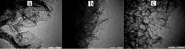
Figure 8. TEM images of (a) NiMCF-1D(R), (b) NiMCF- 2D(R) and (c) NiMCF-3D (R).
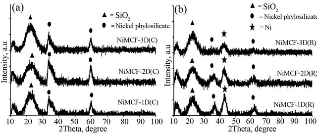
Figure 9. XRD patterns of (a) calcined catalyst samples of NiMCF-1D(C), NiMCF-2D(C), NiMCF-3D(C) and (b) reduced catalyst samples of NiMCF-1D(R), NiMCF-2D(R), NiMCF-3D(R).
confirmed that most of the nickel phylosilicates were converted into nickel metal during the reduction process. Besides that, XRD pattern of the NiMCF-3D(R) displayed a weaker and broader peak at 2θ = 44˚ compared to that of NiMCF-1D(R) and NiMCF-2D(R) catalysts.
This result suggested nickel particles dispersed in NiMCF-3D(R) catalyst were of smaller sizes compared than those in NiMCF-1D(R) and NiMCF-2D(R). This observation was also consistent with SEM and TEM results.
It has been suggested that minor amount of unreduced nickel ions on the silica support could remain at the interface of nickel metal-silica surface as proved by some experimental and theoretical studies [45-49]. This condition was due to strong interaction between nickel phylosilicate and silica surface [50]. These nickel ions attached to the silica surface would act as grafting sites for the metal nanoparticles. The nanoparticles could stabilize the dispersion of nickel particles to prevent them from aggregating or undergoing sintering during high temperature treatment [30].
4. Conclusion
Incorporation of nickel nanoparticles into MCF silica materials prepared at an aging temperature of 80˚C and various aging times (1, 2 and 3 days) was successfully carried out. The increase in aging time resulted in an increase in window pores size in the MCF materials. Meanwhile, total surface area and pore volume were found to decrease. Nickel nanoparticle incorporation into the MCF silica materials was achieved using a deposition-precipitation method at 90˚C for two hours followed by a reduction process for 2.5 h at 550˚C. The window size was the critical dimension controlling the nickel nanoparticle incorporation. Among the MCF silica with various window pore sizes used in this study, the MCF support with an aging time of 3 days (MCF-3D) achieved the highest window pore size. As such, more nickel nanoparticles were incorporated into the MCF-3D support trough the window pore size. The corresponding nickel funtionalized MCF (NiMCF-3D(R)) catalyst had the highest nickel content (17.57 wt%) and the smallest sizes of nickel nanoparticles (1 - 2 nm) together with high porosity as confirmed in SEM and EDX results.
5. Acknowledgements
Research university (RU) grant from Universiti Sains Malaysia to support this research work is gratefully acknowledged. Lilis Hermida also thanks the Directorate General of Higher Education (DIKTI), Ministry of National Education of Indonesia for her PhD scholarship.
REFERENCES
- T. Maschmeyer, “Derivatised Mesoporous Solids,” Current Opinion in Solid State and Materials Science, Vol. 3, No. 1, 1998, pp. 71-78. doi:10.1016/S1359-0286(98)80068-5
- T. M. Lancaster, S. S. Lee and J. Y. Ying, “Effect of Surface Modification on the Reactivity of MCF-Supported IndaBOX,” Chemical Communications, Vol. 28, 2005, pp. 3577-3577. doi:10.1039/b506205e
- W. F. Taylor, D. J. C. Yates and J. H. Sinfelt, “Catalysis over Supported Metals. II. The Effect of the Support on the Catalytic Activity of Nickel for Ethane Hydrogenolysis,” Journal of Physical Chemistry, Vol. 68, No. 10, 1964, pp. 2962-2966. doi:10.1021/j100792a038
- K. Niu, D. Shi, W. Dong, M. Chen and N. Zhongbin, “Chelating Template-Inducedencapsulation of NiO Cluster in Mesoporous Silica via Anionic Surfactant-Templated Route,” Journal of Colloid and Interface Science, Vol. 362, No. 1, 2011, pp. 74-80. doi:10.1016/j.jcis.2011.06.038
- L. Hermida, A. Z. Abdullah and A. R. Mohamed, “Post Synthetically Functionalized SBA-15 with Organosulfonic Acid and Sulfated Zirconia for Esterification of Glycerol to Monoglyceride,” Journal of Applied Sciences, Vol. 10, No. 24, 2010, pp. 3199-3206. doi:10.3923/jas.2010.3199.3206
- V. Degirmenci, A. Yilmaz and D. Uner, “Selective Methane Bromination over Sulfated Zirconia in SBA-15 Catalysts,” Catalysis Today, Vol. 142, No. 1-2, 2009, pp. 30- 33. doi:10.1016/j.cattod.2009.01.011
- T. Huang and W. Tu, “Modification of Functionalized Mesoporous Silica on the Formation and the Catalytic Performance of Platinum Nanocatalysts,” Applied Surface Science, Vol. 255, No. 17, 2009, pp. 7672-7678. doi:10.1016/j.apsusc.2009.04.134
- L. Hermida, A. Z. Abdullah and A. R. Mohamed, “Synthesis of Monoglyceride through Glycerol Esterification with Lauric Acid over Propyl Sulfonic Acid Post-Synthesis Functionalized SBA-15 Mesoporous Catalyst,” Chemical Engineering Journal, Vol. 174, No. 2-3, 2011, pp. 668-676.
- R. I. Kureshy, I. Ahmad, K. Pathak, N. H. Khan, S. H. R. Abdi and R. V. Jasra, “Sulfonic acid Functionalized Mesoporous SBA-15 as an Efficient and Recyclable Catalyst for the Synthesis of Chromenes from Chromanols,” Catalysis Communications, Vol. 10, No. 5, 2009, pp. 572-575. doi:10.1016/j.catcom.2008.10.035
- L. Hermida, A. Z. Abdullah and A. R. Mohamed, “Effect of Functionalization Conditions of Sulfonic Acid Grafted SBA-15 on Catalytic Activity in the Esterification of Glycerol to Monoglyceride: a Factorial Design Approach,” Journal of Porous Materials, Vol. 19, 2012, pp. 835-846. doi:10.1007/s10934-011-9538-x
- J. Chen, J. Zhou, R. Wang and J. Zhang, “Preparation, Characterization, and Performance of HMS-Supported Ni Catalysts for Hydrodechlorination of Chorobenzene,” Industrial and Engineering Chemistry Research, Vol. 48, No. 8, 2009, pp. 3802-3811.
- D. Liu, R. Lau, A. Borgna and Y. Yang, “Carbon Dioxide Reforming of Methane to Synthesis Gas over Ni-MCM-41 Catalysts,” Applied Catalysis A: General, Vol. 358, No. 2, 2009, pp. 110-118. doi:10.1016/j.apcata.2008.12.044
- D. Liu, X. Y. Quek, H. H. A. Waha, G. Zeng, Y. Li and Y. Yang, “Carbon Dioxide Reforming of Methane over Nickel-Grafted SBA-15 and MCM-41 Catalysts,” Catalysis Today, Vol. 148, No. 3-4, 2009, pp. 243-250. doi:10.1016/j.cattod.2009.08.014
- R. Nares, J. Ramirez, A. Gutierrez-Alejandre and R. Cuevas, “Characterization and Hydrogenation Activity of Ni/Si(Al)-MCM-41 Catalysts Prepared by Deposition Precipitation,” Industrial and Engineering Chemistry Research, Vol. 48, No. 3, 2009, pp. 1154-1162. doi:10.1021/ie800569j
- M. Nele, A. Vidal, D. I. L. Bhering, J. V. Pinto and V. M. M. Salim, “Preparation of High Loading Silica Supported Nickel Catalyst: Simultaneous Analysis of the Precipitation and Aging Steps,” Applied Catalysis A: General, Vol. 178, No. 2, 1999, pp. 177-189. doi:10.1016/S0926-860X(98)00285-3
- R. Ryoo and S. Jun, “Improvement of Hydrothermal Stability of MCM-41 Using Salt Effects during the Crystallization Process,” The Journal of Physical Chemistry B, Vol. 101, No. 3, 1997, pp. 317-320. doi:10.1021/jp962500d
- S. Inagaki, Y. Sakamoto, Y. Fukushima and O. Terasaki, “Pore Wall of a Mesoporous Molecular Sieve Derived from Kanemite,” Chemistry of Materials, Vol. 8, No. 8, 1996, pp. 2089-2095. doi:10.1021/cm960115v
- K. A. Koyano and T. Tatsumi, “Synthesis of TitaniumContaining MCM-41,” Microporous Materials, Vol. 10, No. 4-6, 1997, pp. 259-271. doi:10.1016/S0927-6513(97)00016-3
- P. Schmidt-Winkel, et al., “Mesocellular Siliceous Foams with Uniformly Sized Cells and Windows,” Journal of the American Chemical Society, Vol. 21, No. 1, 1999, pp. 254-255. doi:10.1021/ja983218i
- J. S. Lettow, et al., “Hexagonal to Mesocellular Foam Phase Transition in Polymer-Templated Mesoporous Silicas,” Langmuir, Vol. 16, No. 22, 2000, pp. 8291-8295. doi:10.1021/la000660h
- D. T. On and S. Kaliaguine, “Zeolite-Coated Mesostructured Cellular Silica Foams,” Journal of the American Chemical Society, Vol. 125, No. 3, 2003, pp. 618-619. doi:10.1021/ja028656a
- Q. Li, Z. Wu, D. F. Eng, B. Tu and D. J. Zhao, “Hydrothermal Stability of Mesostructured Cellular Silica Foams,” The Journal of Physical Chemistry C, Vol. 114, No. 11, 2010, pp. 5012-5019. doi:10.1021/jp9100784
- Y. J. Han, J. T. Watson, G. D. Stucky and A. Butler, “Catalytic Activity of Mesoporous Silicate-Immobilized Chloroperoxidase,” Journal of Molecular Catalysis B, Vol. 17, No. 1, 2002, pp. 1-8. doi:10.1016/S1381-1177(01)00072-8
- Y. Han, S. S. Lee and J. Y. Ying, “Siliceous Mesocellular Foam for High-Performance Liquid Chromatography: Effect of Morphology and Pore Structure,” Journal of Chromatography A, Vol. 1217, No. 26, 2010, pp. 4337- 4343. doi:10.1016/j.chroma.2010.04.041
- P. Schmidt-Winkel, C. J. Glinka and G. D. Stucky, “Microemulsion Templates for Mesoporous Silica,” Langmuir, Vol. 16, No. 2, 2000, pp. 356-361. doi:10.1021/la9906774
- P. Schmidt-Winkel, et al., “Microemulsion Templating of Siliceous Mesostructured Cellular Foams with Well-Defined Ultralarge Mesopore,” Chemistry of Materials, Vol. 12, No. 3, 2000, pp. 686-696. doi:10.1021/cm991097v
- J. Kim, R. J. Desch, S. W. Thiel, V. V. Guliants and N. G. Pinto, “Adsorption of Biomolecules on Mesostructured Cellular Foam Silica: Effect of Acid Concentration and Aging Time in Synthesis,” Microporous and Mesoporous Materials, Vol. 149, No. 1, 2012, pp. 60-68. doi:10.1016/j.micromeso.2011.08.031
- C. Louis, “Deposition-Precipitation of Supported Metal Catalysts,” In: J. Regalbuto, Ed., Catalyst Preparation Science and Engineering, Taylor and Francis, Inc., New York, 2007, pp. 319-340.
- P. Burattin, M. Che and C. Louis, “Molecular Approach to the Mechanism of Deposition-Precipitation of the Ni(II) Phase on Silica,” The Journal of Physical Chemistry B, Vol. 102, No. 15, 1998, pp. 2722-2732. doi:10.1021/jp980018k
- R. Iler, “The Chemistry of Silica,” John Wiley & Sons, New York, 1979.
- P. Burattin, M. Che and C. Louis, “Ni/SiO2 Materials Prepared by Deposition-Precipitation: Influence of the Reduction Conditions and Mechanism of Formation of Metal Particles,” The Journal of Physical Chemistry B, Vol. 104, No. 45, 2000, pp. 10482-10489. doi:10.1021/jp0003151
- P. Burattin, M. Che and C. Louis, “Metal Particle Size in Ni/SiO2 Materials Prepared by Deposition-Precipitation: Influence of the Nature of the Ni(II) Phase and of Its Interaction with the Support,” The Journal of Physical Chemistry B, Vol. 103, No. 30, 1999, pp. 6171-6178. doi:10.1021/jp990115t
- G. A. Martin, C. Mirodatos and H. Praliaud, “Chemistry of Silica-Supported Catalysts: Preparation, Activation and Reduction,” Applied Catalysis, Vol. 1, No. 6, 1981, pp. 367-382. doi:10.1016/0166-9834(81)80054-1
- M. Piumetti, et al., “Novel Vanadium-Containing Mesocellular Foams (V-MCF) Obtained by Direct Synthesis,” Microporous and Mesoporous Materials, Vol. 142, No. 1, 2011, pp. 45-54. doi:10.1016/j.micromeso.2010.11.010
- Y. M. Liu, et al., “Structure and Catalytic Properties of Vanadium Oxide Supported on Mesocellulous Silica Foams (MCF) for the Oxidative Dehydrogenation of Propane to Propylene,” Journal of Catalysis, Vol. 239, No. 1, 2006, pp. 125-136. doi:10.1016/j.jcat.2005.12.028
- A. Koriakin, K. M. Ponvel and C. H. Lee, “Denitrogenation of Raw Diesel Fuel by Lithium-Modified Mesoporous Silica,” Chemical Engineering Journal, Vol. 162, No. 2, 2010, pp. 649-655. doi:10.1016/j.cej.2010.06.014
- X. Yan, et al., “Amine-Modified Mesocellular Silica Foams for CO2 Capture,” Chemical Engineering Journal, Vol. 168, No. 2, 2011, pp. 918-924. doi:10.1016/j.cej.2011.01.066
- Y. M. Liu, et al., “Chromium Supported on Mesocellular Silica Foam (MCF) for Oxidative Dehydrogenation of Propane,” Catalysis Letters, Vol. 106, No. 3-4, 2006, pp. 145-152. doi:10.1007/s10562-005-9622-4
- K. S. W. Sing, “Adsorption Methods for the Characterization of Porous Materials,” Advances in Colloid and Interface Science, Vol. 76-77, 1998, pp. 3-11. doi:10.1016/S0001-8686(98)00038-4
- T. J. Barton, et al., “Tailored Porous Materials,” Chemistry of Materials, Vol. 11, No. 10, 1999, pp. 2633-2656. doi:10.1021/cm9805929
- K. S. W. Sing, et al., “Reporting Physisorption Data for Gas/Solid System-With Special Reference to the Determination of Surface and Porosity,” Pure and Applied Chemistry, Vol. 57, No. 4, 1985, pp. 603-618. doi:10.1351/pac198557040603
- C. Na-Chiangmai, et al., “Characteristics and Catalytic Properties of Mesocellular Foam Silica Supported Pd Nano Particles in the Liquid-Phase Selective Hydrogenation of Phenylacetylene,” Catalysis Letters, Vol. 141, No. 8, 2011, pp. 1149-1155. doi:10.1007/s10562-011-0593-3
- D. J. N. Subagyono, Z. Liang, G. P. Knowles and A. L. Chaffee, “Amine Modified Mesocellular Siliceous (MCF) as a Sorbent for CO2,” Chemical Engineering Research and Design, Vol. 89, No. 9, 2011, pp. 1647-1657. doi:10.1016/j.cherd.2011.02.019
- P. Burattin, M. Che and C. Louis, “Characterization of the Ni(II) Phase Formed on Silica Upon Deposition-Precipitation,” The Journal of Physical Chemistry B, Vol. 101, No. 36, 1997, pp. 7060-7074. doi:10.1021/jp970194d
- T. Huizinga and R. Prins, “ESR Investigations of Platinum Supported on Alumina and Titania,” The Journal of Physical Chemistry, Vol. 87, No. 1, 1983, pp. 173-176. doi:10.1021/j100224a037
- P. Turlier, H. Praliaud, P. Moral, G. A. Martin and J. A. Dalmon, “Influence of the Nature of the Support on the Reducibility and Catalytic Properties of Nickel: Evidence for a New Type of Metal Support Interaction,” Applied Catalysis, Vol. 19, No. 2, 1985, pp. 287-300. doi:10.1016/S0166-9834(00)81751-0
- L. Bonneviot, M. Che, D. Olivier, G. A. Martin and E. J. Freund, “Electron Microscopy and Magnetic Studies of the Interaction between Nickel and Silica: Considerations on Possible Anchoring Sites,” The Journal of Physical Chemistry, Vol. 90, No. 10, 1986, pp. 2112-1217. doi:10.1021/j100401a026
- H. Haberlandt and F. J. Ritschl, “Quantum Chemical Investigation of Support-Metal Interaction and Their Influence on Chemisorptions. 2. Strong Metal Support Interaction in H-Ni-MOx (M = Ti, Si),” The Journal of Physical Chemistry, Vol. 90, No. 18, 1986, pp. 4322-4330. doi:10.1021/j100409a020
- M. Che, D. Masure and P. Chaquin, “Theoretical Study of the Formation of Oxidesupported Metal Particles: Strength of the Chemical Glue as Represented by Transition Metal Ions at the Metal-Oxide Interface,” The Journal of Physical Chemistry, Vol. 97, No. 35, 1993, pp. 9022-9027. doi:10.1021/j100137a030
- J. W. E. Coenen, “Characterization of the Standard Nickel Silica Catalyst Euroni-1: III. Investigations of CatalystStructure,” Applied Catalysis, Vol. 75, No. 1, 1991, pp. 193-223. doi:10.1016/S0166-9834(00)83132-2
NOTES
*Corresponding author.