Journal of Modern Physics
Vol.06 No.01(2015), Article ID:53438,11 pages
10.4236/jmp.2015.61007
An Approach to Plasma Wake Studying
Gennadii V. Gembarzhevskii
Russian Academy of Sciences, The Institute for Problems in Mechanics, Moscow, Russia
Email: gvgemb@ipmnet.ru
Copyright © 2015 by author and Scientific Research Publishing Inc.
This work is licensed under the Creative Commons Attribution International License (CC BY).
http://creativecommons.org/licenses/by/4.0/


Received 30 October 2014; accepted 11 November 2014; published 22 November 2014
ABSTRACT
The influence of a glow electrical discharge on the wake behind two cylinders was studied. This effect consists in a redistribution of the power in the velocity pulsation spectrum due to the discharge action on fluid flow. To treat this observation, we need a simple model of intermittent turbulent wake in the vicinity of cylinders. A variant of such model has been developed in the form of two coupled van-der-Pole oscillators representing two interacting von Karman vortex streets behind the cylinders. According to the model, the set of the global wake modes and its concurrence are discussed. Accordingly, a mechanism of the glow discharge effect on the cylinders wake has been proposed.
Keywords:
Turbulentplasma Wake, Alternation, Over-Heating Instability, Reduced-Order Model, Van-der-Pole Oscillators, Vortex Streets Synchronization

1. Introduction
During last century the wake behind cylinders attracted considerable attention and now the research for that is in progress. Such contemporary investigations are of various types, namely, of experimental, numerical, theoretical, and complex ones [1] -[9] . Some recent topic is a flow control over moving body for various aims, such as a delay of laminar regime, or triggering flow separation, heat- and mass-flux modification, etc. Among various types of appropriate actuator for flow control an electrical ones have sufficient advantages, such as the fast response, reliability, low cost [10] [11] . Accordingly, dielectric barrier and corona discharges were intensively studied for such purposes. Among many of them, few examples of flow modification by means of plasma actuators around bluff (cylinders) and smooth bodies (wings) were described in references [12] - [15] .
The problem of our direct interest is in the field of plasma wakes, more exactly, turbulent flows in electrical constant power industrial lasers of kW class, some relevant references to this topic are in papers [16] - [19] . We tried to adopt the technique of flow control by the electrical discharge in the fast-flow CO2-laser where the glow discharge exists ab initio. A promising result has been achieved for this case [20] . In that study the wake from two parallel circular cylinders in the side-by-side arrangement was studied for the mixture composed of 16 Torr nitrogen and 2 Torr helium, see Figure 1. The cross section of the discharge chamber was of 55 ´ 940 mm, the diameter of the quartz cylinders was of 15 mm while the diameter of the copper water-cooled cathode was of 4 mm. The cylinders touched the cathode. This cylinders wake may be treated as a incompressible turbulent flow since the value of the flow Mach number was of  and the value of Reynolds number defined in terms of cylinder diameter
  and non-perturb velocity was Re ~ 1000. Mean velocity was measured by means of Prandtl tube. One-point spectra of the wake velocity were measured in 120 mm beneath the axis of one cylinder by means of a transducer of Siddon-Ribner type [21] . Its signal was processed by a PALSE 3560C complex of Bruel & Kjar. Experimental velocity spectra for the wake at non-self-sustained glow discharge and appropriate spectra for the neutral gas flow (that is a reference data) were compared. When the distance between cylinder axes was about
  as is in Figure 2, the velocity spectrum with one peak was observed in the case of gas wake. This result was treated as a manifestation of the presence of one global hydrodynamic mode existing in the case of gas wake with above mentioned parameters. On the contrary, for a relevant plasma wake flow the two-peak velocity spectrum was observed and interpreted as a property of intermittent flow of two concurrent global modes. One of global modes of the plasma wake was the same as for neutral gas flow (since its oscillation frequency was the same), whereas another new mode had lower frequency as compared to previous one. When current density at cathode tube was of about
  (the case in Figure 2(b)) the dominant part of the energy of coherent oscillations was concentrated in the lower frequency peak. Consequently, this discharge influence appeared to be strong.
2. Model of the Wake behind Two Cylinders
For treatment of the discharge effect one has to use some model of the wake. Moreover, when the flow visualization is difficult as it is in our case, even spectral peak classification (of one-point velocity record) requires for some model of the wake. Accordingly our first purpose was developing wake model, no matter appreciable for neutral gas wakes only, but with wide applicability area in Reynolds number variation and in the cylinder spacing alternation. Desirable model has to be the most simple yet leaves room for further extension to such factors as electric discharge influence. Simple wake models are reduced-order models of Landau type, for example [22] . This model is well-studied and justified for low value of supercriticality ,
, . In Russia Prof. P. Landa develops similar reduced-order oscillatory models for various physical systems including wakes (with Prof. A. Ginevsky) as well [23] . We used such approach for turbulent wake modeling with van-der- Pole equation as the starting point, accordingly, no immediate limitation on Reynolds number arises for this option. In experiment [20] in the chamber of fast-flow CO2-laser the cylinders of low aspect ratio were used:
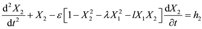
 . This circumstance allows us neglect the wake dynamics in direction of cylinders axes, according to results [24] . On the author hand, it is desirable to have model appreciable for wide range of interaction intensity of von Karman streets. Then the developed model of the wake from two cylinders with side-by-side arrangement is a set of two dimensionless differential equations for coupled van-der-Pole oscillators representing two interfering Benard-von Karman streets behind cylinders in proximity (how the streets were worked out by the end of the formation zone):

Figure 1. Scheme of the wake flow in the discharge chamber.

Figure 2. Spectra of the wake velocity pulsations (arbitrary units): for neutral gas flow (a), and for discharge plasma wake (b).
 (1)
(1)
 (2)
(2)
Here the oscillator coordinates  and
and  represent the transversal components of the flow velocity in two von Karman streets behind two cylinders respectively. Right-hand sides of the equations describe random forces executed on the zone of street formation by the turbulence of incoming flow. Equation set (1, 2) has three dimensionless parameters. Precisely,
  is the native nonlinearity parameter of the partial van-der-Pole oscillator-street,
  and
and  are two parameters of the oscillators cross damping. Here, the peculiarity of this model should be underlined. In an attempt to extend the applicability area of the model, the oscillators coupling form was made nonlinear, accordingly, the term in brackets in set (1, 2) is a square polynomial of general form. Assuming quasi-stationary state of the wake behind the formation zone, the model transforms to a one-dimensional type through the transformation
 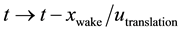 as it is done for Landau model [22] . Moreover, direct experimental evaluation of nonlinearity parameter
 , by treating velocity oscillograms of transient wake regimes, led to value
  for our case [20] [25] and new notation of set (1, 2). As parameter
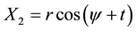
  is small the Poincare-Krylov-Bogolyubov method of slow amplitudes and phases [26] has been applied for solving the set (1, 2) by using the form:
 (3)
(3)
 (4)
(4)
Here  and
and  are the amplitudes whereas
  and
and  are the phases of the first and the second oscillator, respectively. Then, corresponding set of “truncated” equations (that means a neglect of the small impact of the overtones in the case
 ) can be written as
 (5)
(5)
 (6)
(6)
 (7)
(7)
Here, it was introduced the phase difference  for two oscillators-streets
 (8)
(8)
Equations set (5-7) for the case of zero right-hand sides  may be analyzed by seeking for the “laminar” global wake modes, and this work was originally performed by us. The results of this analysis were presented at XII Moscow Workshop on Magneto-Plasma Aerodynamics―2013 [27] . But at this point it is useful to make a change of dependent variables for simplifying the model set. This transformation is
 (9)
(9)
 (10)
(10)
 (11)
(11)
Accordingly, the model of the wake behind the cylinders pair in the side-by-side arrangement takes the final form:
 (12)
(12)
 (13)
(13)
 (14)
(14)
One can see that the developed model (Equations (12-14)) turns out to be relatively simple. Actually, small nonlinearity parameter  may be excluded through the transformation
  then the model becomes a two- parametric one with parameters
  and
and . Moreover, the first two equations for
  and
and  evolution are practically independent of the third equation for
  dynamics. According to the sense of the model, stable stationary points of Equations (12-14) with zero right-hand sides
  represent global modes of the wake. Then the system of the wake modes are i) - iv).
i) Asymmetric mode “ ” with one von Karman street of the complex wake is damped. It has the form:
 (15)
(15)
The domain of existence of  mode is
 (16)
(16)
ii) The second one is symmetric mode “ ” of in-phase synchronized equal oscillators-streets. Its form is:
 (17)
(17)
The domain of existence of  mode is:
 (18)
(18)
iii) Symmetric mode “ ” of anti-phase synchronized von Karman streets has the form:
 (19)
(19)
The existence domain of this mode is as follows:
 (20)
(20)
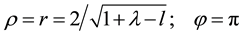
iv) Symmetric mode “ ” consists of two equal von Karman streets synchronized by angular
  depended on
  and
and  parameters. This mode has the form:
 (21)
(21)
The global mode  exists in a simply connected domain
 (22)
(22)
It should be mentioned that the modes  and
and  are twice degenerate ones according to Equations (15) and (21). For convenience the existence map on the
  -plane for the wake modes is presented in Figure 3.
Remark (1): In the area VI in Figure 3: 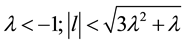 an infinitely growing mode arises. Remark (2):
Three modes ,
,  and
and  demonstrate the effect of oscillation synchronization of two parts of complex systems in the case of weak interaction force between them, see [23] [28] . The asymmetric mode
  belongs to an opposite case of strongly coupled subsystems. In summary, the two-parametric
  -model developed is rich enough to cover four global modes of the cylinder parewake, two of them are twice degenerate.
3. Modeling the Intermittent Turbulent Wake
3.1. Intermittent Wake of Weakly Coupled Streets
From the map in Figure 3 one can easily see that the alternating wake may be observed in wide triangle III:
 (23)
(23)
Moreover, these are modes of in-phase  and anti-phase
  synchronized streets that may coexist in this triangle of parameters. Next step of the model development is a calculation of the alternation coefficient for these two wake modes. With this aim one has to trace the attraction domains of S0 and
  modes in the model

Figure 3. Map of regimes of two-cylinder wake: the mode AS exists in the domain I; S0 in II; S0 and Sπ in III; Sπ in IV; Sφ in V; VI is a nonphysical domain.
phase space. This task may be achieved by taking into consideration the following arguments. The boundary of these domains on  plane is a certain trajectory of the model set (12-14). Due to this fact, the equation for the boundary takes the form
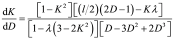 (24)
(24)
This special trajectory must joint unstable stationary points of set (12 - 14) with , then the necessary boundary condition for Equation (24) may be written as
 (25)
(25)
In real time the motion along the boundary is unstable. Accordingly, one has to distinguish between three possibilities when numerical calculating this boundary. In the first case, for the domain of the model parameters , the boundary condition to Equation (24) must be given at the first point (25) in the form
 , as it is a saddle point. For the second aria of parameters
 , the boundary condition has to be given at the second point (25) in the form
 (as well a saddle point for the case). And in the third case
 one must account for two solutions from both boundary points (25). Those so-
lutions merge at the point ,
, 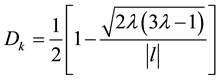 which is an unstable knot in the
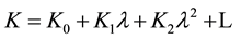
case. Some examples of numerical calculation of boundary curve are presented in Figure 4.
Here some comment may be done. The boundary curve  appears to be a monotonically increasing func-
tion of its variable D for positive values of its parameter  and is a mirror-symmetry decreasing func-
tion of D for negative values of parameter  since K is an odd function of parameter
  according to the model set (12), (13), (14). It seems physically natural that the appearing probabilities for modes
  and
and  occurs to be equal for the case
 , i.e. the boundary curve in Figure 4 approaches the value
  when the initial representation point in the phase space is far from both attraction points
 . But these probabilities diverge from value 50% if the initial representation point moves closer to the attraction points (
 in Figure 4). Naturally, the sign of this separation depends on the sign of the parameter
  that may be easily seen from the form of the last bracket in the phase dynamic Equation (12).
Now we are ready to evaluate the alternation coefficient of the wake within the framework of the model. Let the turbulence intensity of incoming flow be large. This factor is modeled by the right-hand sides of the Equations (1), (2), Equations (5)-(7) and Equations (12)-(14) according to the model developed. Then, for the case of strong interruptions regime, the mean residence time for each compete mode would be proportional to the area of the attraction domains for corresponding mode. Hence, for this case of strong incoming turbulence, the alternation coefficient of the wake may be defined as:
 (26)
(26)
Here this alternation coefficient is defined by the emergence of the mode of anti-phase synchronized streets. (Somebody may prefer the coefficient  defined by the emergence of the mode of in-phase synchronized streets.)According to definition (26) and the problem formulation (24, 25), the alternation coefficient
  may be calculated numerically. Another opportunity reduces to developing an analytical approximate solution of the boundary problem (24, 25) in the form of a truncated expansion. Now the main interest is in the wake of

Figure 4. Boundary of the attraction domains of modes in the phase space: (a) for case λ = 0.2; l = 0.2, (b) for case λ = 0.6; l = 0.2.
weakly coupled von Karman streets. In the case of first domain of parameters  one may use an expansion in small parameter
 .
.
 (27)
(27)
By this way one comes to relevant expansion of the alternation coefficient  with the same small parameter.
 (28)
(28)
 (29)
(29)
Here the new parameter  and constants
  and
and  are introduced. Their definitions are following
 (30)
(30)
 (31)
(31)
 (32)
(32)
Results of such numerical (dots) and analytical (solid curves) evaluation of the alternation coefficient  are presented in Figure 5.
Remark (1): Alternation coefficient is an odd function of parameter  or
or  due to the symmetry properties of the model, accordingly, the data adduced in Figure 5 are for the case of positive interval of
  variation only. Remark (2): It should be noted that the difference between analytical data (28, 29) and numerical results is not so large even for maximum value of the expansion parameter
 . Summary of the results is as follows. The alternation coefficient
  of
of  and
and  wake modes in domain
  varies in the interval
 . It relatively strongly depends on the first model parameter
 , whereas its dependence on the second parameter
  is relatively weak. Precisely,
  is a monotonically decreasing function of
 . This feature follows from the first boundary condition (25) for the equation (24):
 . And the alternation coefficient
  is a monotonically increasing function of
  for the case
 .
.
3.2. Intermittent Wake of Strongly Coupled Streets
When considering the case of strongly coupled von Karman streets , one can recognize some other possibility for intermittent regime existence within the framework of the model. From the map in Figure 3 it can be seen that this intermittent regime may realize at the line
 (33)
(33)
Fortunately, for this case, the general solution for the phase trajectory on  plane may be written in explicit form
 (34)
(34)
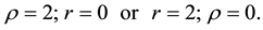
Here C is an arbitrary constant. Figure 6 is the illustration of phase trajectories for the case. Here points  and
and  are stable, accordingly mode
  is also stable. Moreover, there are quasi-stable states within the framework of the model for the case
 . These quasi-stable states are not points but intervals
 (35)
(35)
In the case  these states exists in two intervals
 (36)
(36)

Figure 5. Intermittence coefficient Γπ as a function of the model parameters p = l/2λ and λ. The last parameter monotonically grows from low curve to top curve: λ = 0.01; 0.05; 0.1; 0.2; 0.333, respectively; whereas the first parameter p is positive for all curves.
Figure 6. Oscillators-streets dynamics for the case λ = 1; (a) for case l = 1.8, (b) for case l = 6.
For symmetric case  one has intervals of existence
 (37)
(37)
These conclusions are easily seen from the form of general solution (34) of dynamic equations illustrated by Figure 6. Here upper line  represents quasi-stable mode of in-phase synchronized streets of different strength
 , when lover line
  corresponds to anti-phase synchronized quasi-stable streets of different strength. Let these modes of two unequal streets be named
  and
and , respectively. For clearness, the phase trajectories ending at
  wake mode are market green when those ending at
  mode are market blue in Figure 6, and the separatrix is red. So, within the framework of the model, the only case when strongly coupled von Karman streets may alternate is the line
 . Three modes alternate at this one-dimen- sional domain, namely: stable mode
  and two quasi-stable modes
  and
and .
.
4. Approbation of the Model
The multiplicity of wake modes existing for two cylinders in side-by-side configuration is well known from the visualization experiments and as well as from simulations. The developed model managed to cover four global modes of the cylinders wake. There are modes of in-phase and anti-phase synchronized streets among four of them. It is known that these modes exist in the case of a relatively weak interaction of the von Karman streets formed by each cylinder when the cylinders are not so close to each other (see, for example [3] [29] ). And the intermittent wake regime of these two modes is known for some wake parameters, as well [29] . Our two-di- mensional wake model also brings to a restriction of existence domain of  mode at low
  ratio but not at high
  values [30] . All this facts related to modes of in-phase and anti-phase synchronized streets appear to be in a good agreement with our one-dimensional model predictions. The third mode of the model
  is an asymmetric mode with one of the vortex streets damped. It must be attributed to the case of relatively strong interaction of von Karman streets when “deflected flow” and “flip-flop” regimes were visualized and evaluated, for example in references [3] [22] [31] [32] . The last fourth mode of the model
  represents the wake in the form of two equal streets synchronized by the angle being not equal to 0 or
 . Some similar wake configurations may be observed. Then the question of whether they are stable or transient arises? Existence of two quasi-stable modes
  and
and  do not contradict to observations and simulations as well. The model developed is not unique one among other one-dimensional models for the wake from cylinders group. Commonly, some kind of Stuart-Landau model (Landau-Ginzburg model) is used for the wake from cylinders. The earlier papers [22] [32] [33] are examples. An advantage of our wake model as compared to the Stuart-Landau models is a low number of its parameters (only two) in combination with nonlinear form of the street interaction term with these parameters quantity. Therefore, we hope that the domain of its validity is wider as compared to the domain of Stuart-Landau models with linear term of the street coupling and restricted validity aria for the flow Reynolds number.
5. Model Application to Plasma Wake Studying
Formally, one has two possibilities when applying the model to cylinders intermittent wake. These are the cases of weekly (3.1) and strongly (3.2) coupled streets as it was discussed above. The variant of weekly interacting streets is not our case as the frequency splitting of the two observed modes was large enough ~30% (see Figure 2) for  and
and  alternation. Moreover, for such small spacing as
  in our experiment [20] , the mode of anti-phase synchronized streets
  was not observed as it may be concluded from the literature. Accordingly, it only remains to use the case of strongly coupled streets (3.2) with alternating modes
  and
and  (or may be
 ) when describing intermittent plasma wake within the framework of the model for pitch ratio
  in the case. Then, what is the role of the glow electrical discharge in the wake switching from
  global mode (or
  mode) to intermittent regime of
  and
and  (or
(or ) modes? Nonhomogeneous wake heating due to energy release through the discharge may act as some equivalent of the lowering of the cylinders spacing. Consequently, glow discharge switching-on influences on the model parameters. Supposedly, the discharge switching-on increases the model parameter
  similarly to the cylinders spacing influence. Consequently, if the value of the wake parameter
 , one may switch over the wake regime by means of discharge power regulation. Here the interplay of the symmetry properties of the wake hydrodynamic modes and the discharge property of homogeneity breaking at greater currents must be accounted for. Suppose that the parameters of the neutral gas wake lie at the range
 . Hence, the wake state is described by the stable mode
  (or
(or ) according to the model whereas the mode
  is unstable. The same situation is for plasma wake with sufficiently low currents. But for greater currents the development of the plasma overheating process [16] in the case of asymmetric hydrodynamic mode
  changes the parameter
  to such values as
 . It means that the plasma wake at the
  mode becomes stable for such elevated currents, yet the plasma wake at
  (or
(or ) mode remains to be stable
  since the current distribution is more homogeneous due to more homogeneous hydrodynamic parameters distribution of the mode
  as compared to the distribution of the
  mode. Then the
  - and
- and  -modes begin to alternate due to the turbulence of incoming flow. Moreover, one may suppose that the model parameter
  shift between two intermitting modes must be greater for the greater currents, since overheating is a nonlinear process. Thus, one observes a growth of the wake alternation coefficient
  as the discharge current increases [20] .
Realization ability of this scenario depends on amount of the plasma heating effect. The redistribution of power in the velocity spectra was observed at relatively low discharge power  [20] . For an evaluation of discharge influence on the wake one may initially consider the case of the homogeneous distribution of the current density across the chamber and complete vibration relaxation of nitrogen (in collisions with molecular of uncontrolled admixture). Then this heating would be
  to the end of the chamber for our case of nitrogen-helium mixture pressure
 , unperturbed gas velocity
 , and the chamber cross-section area
 . And we really observe considerable heating of the facility housing at plasma outlet from the chamber. Accordingly, we assume that local temperature increase of scale of tens degrees may be caused by the discharge overheating instability process in the case of essential vibration relaxation by admixture. Such sharply non uniform plasma heating would be sufficient to influence the von Karman streets interaction in the critical area of
 . Here, it should be mentioned that a “seed” for the development of this overheating process is available. Really, this seed is local temperature jump at the cathode boundary layer separating. An estimate of this jump with respect to practically unheated surrounding gas is as follows:
 , whereas the thickness of separating dynamic boundary layer is of value
  for the cathode diameter
 . This estimate is realized according to reference [34] for the case of 100% efficiency of the cathode water-cooling, i.e. it was assumed that the temperature of the cathode surface was equal to the temperature of unperturbed incoming gas
 . Here the cathode drop was as
  and its thickness as
 . The whole electric power in cathode fall was assumed to release as heat.
6. Results and Conclusions
At present the study of turbulent plasma wake behind a number of cylinders is in progress. Simple, easily treated, and physically justified model of two cylinders wake in the side-by-side arrangement has been proposed. Actual variant of this two-parametric model covers four global wake modes as well as the intermittent regime. This model works well for the case of weak coupling of the streets, and works worse at strong coupling. Nevertheless, within the framework of advanced model, the observed wake intermittent modes were identified for the pitch ratio value  studied. And mechanism of glow discharge effect on cylinders wake has been proposed within the framework of the model. It bases on the wake symmetry breaking in plasma overheating process. According to the results obtained and investigations planned the version of two-point transducer for velocity oscillation measurement in both plasma and gas wakes was elaborated. The experimental apparatus in combination with advanced model provide a consistent tool for further plasma wake investigation. Work is under way for control the fluctuations in gas flow incoming the facility chamber. In closing it may be said that now the alternation is of special interest [35] , whereas advanced model is an intermittent wake model appropriated for the case of “external” triggered alternation by incoming flow fluctuations.
Main part of these results was briefly presented at the 26-th Symposium on Plasma Physics and Technology, Prague, June 2014.
Acknowledgements
Discussions with Prof. Eduard V. Teodorovich, numerical calculation by Kirill Yu. Osipenko and electronic circuitry work by Aleksandr A. Sirotin are gratefully acknowledged. This study was supported by The Russian Fund for the Basic Researches, grant 13-01-00742.
References
- Sumner, D. (2010) Journal of Fluids and Structures, 26, 849-899. http://dx.doi.org/10.1016/j.jfluidstructs.2010.07.001
- Alam, Md.M., Zhou, Y. and Wang, X.W. (2011) Journal of Fluid Mechanics, 669, 432-471. http://dx.doi.org/10.1017/S0022112010005288
- Peng, Y.F. (2013) Journal of Modern Physics, 4, 89-95. http://dx.doi.org/10.4236/jmp.2013.45B015
- Bao, Y., Zhou, D. and Tu, J. (2013) Computers & Fluids, 71, 124-145. http://dx.doi.org/10.1016/j.compfluid.2012.10.013
- Verma, A. and Mittal, S. (2011) Physics of Fluids, 23, Article ID: 121701. http://dx.doi.org/10.1063/1.3664869
- Zhao, M. and Cheng, L. (2014) Journal of Fluid Mechanics, 751, 1-37. http://dx.doi.org/10.1017/jfm.2014.268
- Assi, G.R.S., Bearman, P.W. and Meneghini, J.R. (2010) Journal of Fluid Mechanics, 66, 365-401. http://dx.doi.org/10.1017/S0022112010003095
- Song, L. and Wu, S. (2013) Applied Mechanics and Materials, 275-277, 482-485. http://dx.doi.org/10.4028/www.scientificnet/AMM.275-277.482
- Luzzatto-Fegiz, P. and Williamson, C.H.K. (2012) Physics of Fluids, 24, Article ID: 066602. http://dx.doi.org/10.1063/1.4724307
- Choi, H., Jeon, W-P. and Kim, J. (2008) Annual Review of Fluid Mechanics, 40, 113-139. http://dx.doi.org/10.1146/annurev.fluid.39.050905.110149
- Corke, T.C., Enloe, C.L. and Wilkinson, S.P. (2010) Annual Review of Fluid Mechanics, 42, 505-529. http://dx.doi.org/10.1146/annurev-fluid-121108-145550
- Moreau, E. (2007) Journal of Physics D: Applied Physics, 40, 605-636. http://dx.doi.org/10.1088/0022-3727/40/3/S01
- Jukes, T.N. and Choi, K.S. (2009) Physics of Fluids, 21, Article ID: 084103. http://dx.doi.org/10.1063/1.3194307
- Sosa, R., Artana, G., Benard, N. and Moreau, E. (2011) Experiments in Fluids, 51, 853-860. http://dx.doi.org/10.1007/s00348-011-1108-0
- Sidorenko, A.A., Budovskii, A.D., Postnikov, B.V., Zverkov, I.D., Zanin, B.Yu., Kozlov, V.V. and Maslov, A.A. (2010) Technical Physics Letters, 36, 304-307. http://dx.doi.org/10.1134/S106378501004005X
- Raizer, Yu.P. (1991) Gas Discharge Physics. Springer-Verlag, Berlin.
- Panchenko, V.Ya., Zavalov, Yu.N., Galushkin, M.G., Grishaev, R.V., Golubev, V.S. and Dubrov, V.D. (2006) Laser Physics, 16, 40-51. http://dx.doi.org/10.1134/S1054660X0601004X
- Huang, H. and Wang, Y. (2010) Optical Engineering, 49, Article ID: 114201. http://dx.doi.org/10.1117/1.3509163
- Osipov, A.I., Uvarov, A.V. and Vinnichenko, N.A. (2006) Physics of Fluids, 18, Article ID: 105106. http://dx.doi.org/10.1063/1.2364261
- Gembarzhevskii, G.V. (2009) Technical Physics Letters, 35, 241-244. http://dx.doi.org/10.1134/S1063785009030146
- Siddon, T.E. and Ribner, H.S. (1965) AIAA Journal, 3, 747-749. http://dx.doi.org/10.2514/3.2963
- Peschard, I. and Le Gal, P. (1996) Physical Review Letters, 77, 3122-3125. http://dx.doi.org/10.1103/PhysRevLett.77.3122
- Landa, P.S. (1996) Nonlinear Oscillations and Waves in Dynamical Systems. Kluwer Academic Publishers, Dordrecht.
- Albarede, P. and Provansal, M. (1995) Journal of Fluid Mechanics, 291, 191-222. http://dx.doi.org/10.1017/S0022112095002679
- Gembarzhevskii, G.V. (2009) The Effect of Flow Structure Transformation Induced by Electric Discharge and Its Simple Model. Contributed Papers, VI International Conference on Plasma Physics and Plasma Technology, Vol. 1, Minsk, 28 September-2 October 2009, 27-30.
- Nayfeh, A.H. (1981) Introduction to Perturbation Techniques. John Wiley & Sons, Hoboken.
- Gembarzhevskii, G.V. and Lednev, A.K. (2013) Reduced Order Model for Effect of Pulsation Energy Redistribution in Cylinders Wake Induced by Glow Discharge. Proceedings of the 12th Workshop on Magneto-Plasma Aerodynamics, Moscow, 26-28 March 2013, 41-44.
- Pikovsky, A., Rosenblum, M. and Kurths, J. (2002) Synchronization: A Universal Concept in Nonlinear Science. Cambridge University Press, Cambridge.
- Williamson, C.H.K. (1985) Journal of Fluid Mechanics, 159, 1-18. http://dx.doi.org/10.1017/S002211208500307X
- Gembarzhevskii, G.V. (2011) Technical Physics Letters, 37, 19-22. http://dx.doi.org/10.1134/S1063785011010020
- Kim, H.J. and Durbin, P.A. (1988) Journal of Fluid Mechanics, 196, 431-448. http://dx.doi.org/10.1017/S0022112088002769
- Le Gal, P., Chauve, M.P., Lima, R. and Rezende, J. (1990) Physical Review A, 41, 4566-4569.
- Provansal, M., Mathis, C. and Boyer, L. (1987) Journal of Fluid Mechanics, 182, 1-22. http://dx.doi.org/10.1017/S0022112087002222
- Schlichting, H. (1955) Boundary Layer Theory. Pergamon Press Ltd., London.
- Budaev, V.P., Savin, S.P. and Zelenyi, L.M. (2011) Physics-Uspekhi, 54, 875-918. http://dx.doi.org/10.3367/UFNe.0181.201109a.0905