Journal of Modern Physics
Vol.5 No.12(2014), Article ID:48110,12 pages
DOI:10.4236/jmp.2014.512112
Power Balance Theorem of Frequency Domain and Its Application
Binghua Huang1, Guangming Li2, Huijie Liu2
1Electrical Engineering School of Guangxi University, Nanning, China
2Dongguan University of Technology, Dongguan, China
Email: gxuhbh@163.com
Copyright © 2014 by authors and Scientific Research Publishing Inc.
This work is licensed under the Creative Commons Attribution International License (CC BY).
http://creativecommons.org/licenses/by/4.0/

![]()

Received 19 May 2014; revised 12 June 2014; accepted 4 July 2014
ABSTRACT
This paper proves a power balance theorem of frequency domain. It becomes another circuit law concerning power conservation after Tellegen’s theorem. Moreover the universality and importance worth of application of the theorem are introduced in this paper. Various calculation of frequency domain in nonlinear circuit possess fixed intrinsic rule. There exists the mutual influence of nonlinear coupling among various harmonics. But every harmonic component must observe individually KCL, KVL and conservation of complex power in nonlinear circuit. It is a lossless network that the nonlinear conservative system with excited source has not dissipative element. The theorem proved by this paper can directly be used to find the main harmonic solutions of the lossless circuit. The results of solution are consistent with the balancing condition of reactive power, and accord with the traditional harmonic analysis method. This paper demonstrates that the lossless network can universally produce chaos. The phase portrait is related closely to the initial conditions, thus it is not an attractor. Furthermore it also reveals the difference between the attractiveness and boundedness for chaos.
Keywords: Tellegen’s Theorem, Harmonic, Conservative System, Chaos, Lossless Circuit

1. Introduction
For the nonlinear differential equation which can not be found from time-domain, the harmonic analysis method attempts to find the harmonic solutions of frequency domain. The attempt can not be completely realized. All harmonic terms of Fourier series expansion can not be solved. However, the main part of the harmonic components can be obtained. It is a feasible way to find the qualitative solution of nonlinear differential equation through combining physics practice. Tellegen’s theorem is the power balance theorem of time domain. This paper extends the theorem to the frequency domain of nonlinear networks. The correlation between time domain and frequency domain solutions can be established.
In fact, it’s impossible to use the law of dynamic mechanics to analyze and research the variation rule of voltage and current in the circuits. It can only be a means of analogy. The movement of phase point (not a particle) does not obey law of mechanics; but it must obey the constraint of state equation. If the state equation is a kind of balance relation based on KCL and KVL, solving the equation may not be directly supported from dynamic mechanics. It can only seek its physical meaning on the field of Electrical Science Theory. The principle of power balance is the universal truth of nature. It can be used to overcome the difficulties encountered in solving the nonlinear equations. It supports the qualitative analysis of the nonlinear equations. The first harmonic can correctly be obtained from the complex power balance theory of the frequency domain [1] -[10] . The main harmonic component in non-autonomous circuits can further be solved by extending the balance theory [11] -[14] . The literatures [15] put forward that this is a new research topic in the nonlinear circuit and chaos field. As for the harmonic analysis method, the literatures [16] put forward some comments about the main harmonic solutions of odd terms equation. The literature [17] applies the energy balance method to analyze the solution of nonlinear equations which involves the balance concept of active power. But it’s unable to analyze the important conclusion of reactive power balance.
There is no definition and academic term of reactive power in dynamics or other disciplines. The power balance theory of the electrical science develops in the forefront of all disciplines. The electrical science establishes the concept of reactive power. It cannot be replaced by other disciplines. Its important significance is to promote the application of balance theorem from active to reactive power.
In domestic and foreign literature, with regard to researching nonlinear circuits and chaos all are established on the basis of dynamic mechanics except the mathematic method of finding differential equations. The balance theory of power opens up a new field for researching nonlinear circuits and chaos. The harmonic analysis method based on complex power balance theory should obtain much more correct and rational result. The theorem proved by this paper propels the Tellegen’s theorem of time domain to frequency domain in nonlinear circuit. Its important contributions on theory are to replenish a vacancy at home and abroad in the academic field today.
2. Each Harmonic Component Individually Obeys KCL and KVL
The instantaneous value of the voltage and current obeys KCL and KVL. Supposing the voltage and current of each branch in the network can be expressed as the sum of multi-harmonic components. The frequency spectrum is discrete and the quantity of harmonic components is limited. Then it can be proved that each harmonic component in the network obeys individually KCL and KVL.
 (1)
(1)
 (2)
(2)
Suppose the
 represents the sum of X branch currents or voltages. If
 represents the currents, the total number X are equal to all branches connecting
to a node; if
represents the currents, the total number X are equal to all branches connecting
to a node; if
 represents the voltages, the total number X are equal to all branches around the
loop. The
represents the voltages, the total number X are equal to all branches around the
loop. The
 is decomposed into a sum of all harmonic components as shown in (1). The
 is considered as a zero harmonic. In (2),
 represents the sum of
 harmonic component for all branch currents flowing into a node that connects with
X branches.
harmonic component for all branch currents flowing into a node that connects with
X branches.
If , then
 which represents the sum of all harmonic current flowing into the node shall be
equal to zero. Conversely, if the total current
which represents the sum of all harmonic current flowing into the node shall be
equal to zero. Conversely, if the total current , whether the current
 of each harmonic is equal to zero or not. That is, for arbitrary t, if
 , whether the current of each harmonic flowing
in a node can be
, whether the current of each harmonic flowing
in a node can be ,
,
 ,
,
 but the sum is
 or not. Taking t as the abscissa, various harmonics
 ,
,
 ,
,
 ,
,
 as the ordinate, drawing them on the plane graph of rectangular
coordinate. Each harmonic component is sine and cosine function with different frequency.
We desire the sum of those functions should be a straight line overlapping with
abscissa. Obviously, it is impossible.
as the ordinate, drawing them on the plane graph of rectangular
coordinate. Each harmonic component is sine and cosine function with different frequency.
We desire the sum of those functions should be a straight line overlapping with
abscissa. Obviously, it is impossible.
If
 represents the sum of the voltage of all branches in a loop,
 is the necessary and sufficient condition for
 . The conclusion demonstrates that the
correlation between time domain and frequency domain. If
. The conclusion demonstrates that the
correlation between time domain and frequency domain. If , each periodic component should be equal
to zero as well. The conclusion shows that unbalanced volume of kth harmonic
component can only be replenished by self, and cannot be replenished by non-kth
harmonic. Each harmonic must individually comply with KCL and KVL but they cannot
replenish each other. Up to now, the proof of the proposition has been completed.
The instantaneous value
, each periodic component should be equal
to zero as well. The conclusion shows that unbalanced volume of kth harmonic
component can only be replenished by self, and cannot be replenished by non-kth
harmonic. Each harmonic must individually comply with KCL and KVL but they cannot
replenish each other. Up to now, the proof of the proposition has been completed.
The instantaneous value
 complies with the circuit laws such as KCL and KVL, so does each harmonic component
of frequency domain. Above laws are independent of specific characters of each branch
(active, passive, linear, nonlinear, volt-ampere characteristic is continuous or
piecewise definition). It’s tenable within the range of all nonlinear characteristics.
complies with the circuit laws such as KCL and KVL, so does each harmonic component
of frequency domain. Above laws are independent of specific characters of each branch
(active, passive, linear, nonlinear, volt-ampere characteristic is continuous or
piecewise definition). It’s tenable within the range of all nonlinear characteristics.
We have to emphasize the following points. 1) The
 shown in (1) are Fourier series expansions. On discrete spectrum, the interval between
two frequency components can be equally spaced, that is
shown in (1) are Fourier series expansions. On discrete spectrum, the interval between
two frequency components can be equally spaced, that is ; However, it can also be unequal interval,
then
; However, it can also be unequal interval,
then . 2) In the network, the total number of all branches
is
. 2) In the network, the total number of all branches
is . 3) The voltage and current in network is divided into
 harmonic components according to the discrete frequency. They are not split into
isolated part; the mutual coupling influence exists among the various harmonic components.
For example, first harmonic voltage will affect third harmonic current, and the
existence of third harmonic voltage will affect first harmonic current.
harmonic components according to the discrete frequency. They are not split into
isolated part; the mutual coupling influence exists among the various harmonic components.
For example, first harmonic voltage will affect third harmonic current, and the
existence of third harmonic voltage will affect first harmonic current.
3. Power Balance Theorem of Frequency Domain
A nonlinear network complies with Tellegen’s theorem, and the network total dissipation of instantaneous power is equal to zero. Thus, it can be proved that the complex power formed by each harmonic component in the network obeys individually the law of conservation. The complex power of each harmonic component here refers to the power produced by the voltage and current with same frequency. It can be expressed as complex power conservation. The power produced by the voltage and current with different frequency cannot be defined as complex power.
Assuming there are m branches in the network, we need to calculate the sum of the
instantaneous power. The total power is marked by . It possesses two types of decomposition.
1) The first one is decomposed into the sum of power of m branches. Obviously, a
network comprises the active branch producing power and the passive branch consuming
power. The total power
 should equal to zero. Thus the formula can be expressed as:
 (3)
(3)
2) The second is decomposed into the sum of
 harmonic components.
 (4)
(4)
In (4),
 represents the instantaneous power of branch-a, the
 and
and
 have individually
 harmonic items, thus
 contains
 harmonic items. Each branch contains the total power of
 harmonic components. There are two kinds of different product terms. One product
containing n + 1 items in total, is formed by the voltage and current with same
frequency. The other product contains
harmonic components. There are two kinds of different product terms. One product
containing n + 1 items in total, is formed by the voltage and current with same
frequency. The other product contains

items which are formed by the voltage and current with different frequency. The
total power
 of the branch-a consists of
 harmonic components as shown in (4).
 (5a)
(5a)
 (5b)
(5b)
 (5c)
(5c)
In (5), each harmonic comprises the total power of m branches. The
 harmonic components can be divided into two types, where the same frequency component
![]() is denoted as
is denoted as
 while different frequency component is denoted as
![]() .
.
If the frequency of each harmonic of the voltage and current is rational number,
then the sun, difference and product of two components have to be a periodic function.
Therefore, each harmonic
 is periodic function, and the direct current component is zero harmonic.
 (6)
(6)
 (7)
(7)
There are m branches in total for the segment network composed by the kth
harmonic shown in (6). Moreover,
 harmonic components are all periodic functions. According
to the correlation between the time domain and the frequency domain, each periodic
component should equal to zero if
harmonic components are all periodic functions. According
to the correlation between the time domain and the frequency domain, each periodic
component should equal to zero if . Therefore, each harmonic component of
 is
is . Notice, the current
 and amplitude
 of kth-harmonic is related to the non-kth-harmonic voltage
amplitude
of kth-harmonic is related to the non-kth-harmonic voltage
amplitude
![]() as shown in (7). It is explained that every harmonic must observe individually conservation
law under the condition of considering mutual coupling influence.
as shown in (7). It is explained that every harmonic must observe individually conservation
law under the condition of considering mutual coupling influence.
 (8a)
(8a)
 (8b)
(8b)
 (9)
(9)
 (10)
(10)
The (8) can be obtained from (7). The kth harmonic power
 in (8) is not only related to the kth-harmonic voltage, but also affected
by the mutual coupling of non-kth-harmonic voltage. The (8) shows the
instantaneous power
in (8) is not only related to the kth-harmonic voltage, but also affected
by the mutual coupling of non-kth-harmonic voltage. The (8) shows the
instantaneous power
![]() of the kth harmonic for branch-a, where the
of the kth harmonic for branch-a, where the
 denotes active power which is a direct, namely considered as a zero harmonic;
 denotes reactive power which is a alternate. The
 and
and
 are two kinds of waveforms of the
![]() . The total instantaneous power
. The total instantaneous power
 of the kth harmonic for all m branches is shown in (9). The
 can be expressed as the sum of
 and
and![]() . If
. If , then
 . Conversely, if
 , then
 hold also. For any t, two kinds of waveforms have to be balanced individually, while
cannot replenish each other. Therefore, the proof of the proposition regarding complex
power conservation has been completed as shown in (10).
hold also. For any t, two kinds of waveforms have to be balanced individually, while
cannot replenish each other. Therefore, the proof of the proposition regarding complex
power conservation has been completed as shown in (10).
4. Coupling Relation among Various Harmonic Must Be Commonly Obeyed
The complex power of each harmonic component has to be conserved individually. However, there is interaction influence of nonlinear coupling among various harmonic. The two general rules are not contradictory. The former refers to the complex power produced by the kth harmonic excited source should equal to the active and reactive power consumed by load impedance. The latter, for nonlinear network, there is nonlinear coupling of interaction influence among various harmonics due to the voltage-controlled nonlinear admittance. The power balance theorem of frequency domain must include coupling relation among various harmonic. Therefore, for the nonlinear network, the balance equations of all harmonic should jointly be solved.
 (11)
(11)
 (12)
(12)
Supposing the voltage
 of nonlinear branch-a as shown in (11) includes two harmonics
 and
and![]() . where
. where
 denotes the frequency of
 , while
![]() denotes the frequency of
denotes the frequency of![]() . The current
. The current
 includes various harmonics, among these harmonics, the
 and
and
![]() are two main components denoted by
are two main components denoted by
 as shown in (11). The program Twoωhp.nb proves the branch current
 of hth-harmonic is related to the pth- harmonic voltage
 as shown in (12), where the
![]() is defined as equivalent h-harmonic conductance. However, the power
is defined as equivalent h-harmonic conductance. However, the power
![]() consumed by the hth harmonic can only be balanced by the power produced
from the harmonics voltage
consumed by the hth harmonic can only be balanced by the power produced
from the harmonics voltage . The
. The
![]() cannot be replenished by the power produced from the
cannot be replenished by the power produced from the![]() . When the nonlinear factor
. When the nonlinear factor , the
, the
 is only determined by the harmonic voltage
 , and
, and
![]() is a linear conductance.
is a linear conductance.
 (13)
(13)
 (14)
(14)
 (15)
(15)
It is established that the nonlinear relationship between
![]() and
and
 is shown in (13), where the
 denotes nonlinear voltage-controlled inductance, the
 , C and
 are constants. Using sinusoidal voltage
 excites
 , and the current differential
![]() includes multiple harmonics. Among those harmonics,
includes multiple harmonics. Among those harmonics,
 is amplitude of the first harmonic, the amplitude ratio
 can be defined as equivalent first harmonic inductance
![]() shown in (14).
shown in (14).
When the connection of two sinusoidal voltage
 in series excites
 , then the
![]() and
and
![]() represent respectively the equivalent inductance of the two main harmonics
represent respectively the equivalent inductance of the two main harmonics
 and
and![]() . The amplitudes
. The amplitudes
 and
and
 of equivalent voltages represent respectively the equivalent contribution after
mutual coupling of two main harmonics shown in (15). The equivalent reactance
of equivalent voltages represent respectively the equivalent contribution after
mutual coupling of two main harmonics shown in (15). The equivalent reactance
![]() shows reactive power consumed by harmonic
shows reactive power consumed by harmonic
 is related to voltage amplitudes of harmonic
![]() . The program Leq.nb solves the above equivalent
values [18] [19]
.
. The program Leq.nb solves the above equivalent
values [18] [19]
.
For example, for an autonomous circuit without external excitation source, the active power cannot be balanced to maintain sustained self-excited oscillation owing to positive damping. There is only forced component for the steady state oscillation. After adding the external excited-source with different frequency, the free selfoscillation component in transient process will finally fail and disappear. The power supplied by the external excited source cannot replenish the vacancy of power of self-excited component. This is the best example which show each harmonic component power must be individually conserved.
5. Solving Main Harmonic of Lossless Circuit Using Power Balance Theorem
The study takes lossless network shown in Figure 1
as an example, it comprises nonlinear inductance . In the network, the circuit includes the components
of self-excited and forced oscillation.
. In the network, the circuit includes the components
of self-excited and forced oscillation.
On the one hand, the balance equation of the reactive power of the self-oscillation component relates to the forced oscillation component; on the other hand, the reactive power vacancy of self-oscillation component cannot be filled by the external excited source. It can only be balanced by means of adjusting own oscillation frequency. Similarly, the forced reactive power supplied by excited source has to be equal to the reactive power consumed by reactance in the network. However, the forced reactive power consumed by nonlinear reactance relates to the existence of self-oscillation component.
The Figure 1 shows a lossless circuit which doesn’t include energy dissipating elements and consume no active power.
Its oscillation character is determined by two oscillation components simultaneously obeying the balance conditions of reactive power. The excited source only supplies reactive current to the circuit which consists of LN and C. After an excitation period, the LNC circuit maintains the energy obtained in initial moment. Taking the Figure 1 circuit as example, this paper demonstrates that the reactive power of two main harmonics is individually conserved; however, there is interaction influence of nonlinear coupling between two main harmonics [18] -[20] .
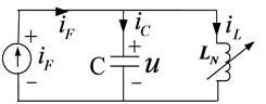
Figure 1. Typical circuit.
5.1. Applying Power Balance Theorem and Phasor Method
 (16)
(16)
 (17)
(17)
 (18)
(18)
![]() (19a)
(19a)
 (19b)
(19b)
 (20)
(20)
Example 1. The state equations and scalar equation of the circuit Figure 1 are shown in (16), parameters of circuit is shown in (17).
The excited source
 is shown in (18). We suppose the solutions of variable u including main harmonic
 and non-main harmonic uN as shown in (19), where
 and
and
![]() represent individually self-excited and forced oscillation component. Its synthesis
is denoted as main harmonic solution
represent individually self-excited and forced oscillation component. Its synthesis
is denoted as main harmonic solution . The relationship between the initial condition
and the amplitude of two main harmonics is shown in (20). The above frequency domain
theorem and phasor method are
applied to Program Power.nb for obtaining the main harmonic solutions in Table1 The phasor
method expressed by complex number is only used for linear circuit to
obtain the superposition solution of two harmonic components before. It has been
proved that each harmonic component should obey individually various balance theorems
after the consideration of coupling influence. Therefore the
phasor method can also be applied to seek the coupling solutions of two
main harmonics. We obtain the data in Table1
. The relationship between the initial condition
and the amplitude of two main harmonics is shown in (20). The above frequency domain
theorem and phasor method are
applied to Program Power.nb for obtaining the main harmonic solutions in Table1 The phasor
method expressed by complex number is only used for linear circuit to
obtain the superposition solution of two harmonic components before. It has been
proved that each harmonic component should obey individually various balance theorems
after the consideration of coupling influence. Therefore the
phasor method can also be applied to seek the coupling solutions of two
main harmonics. We obtain the data in Table1
5.2. Above Results Verified by Harmonic Analysis Method
 (21)
(21)
 (22)
(22)
 (23)
(23)
 (24)
(24)
 (25)
(25)
 (26)
(26)
 (27)
(27)
 (28)
(28)
The cube nonlinear term
 are shown in (21). The (22) can be obtained by substituting (21) into (16), where
 denotes the main harmonic of
 ; the
; the
 denotes the non-main harmonic of
 . The
equilibrium equation
of non-main harmonic is shown in (23). The
. The
equilibrium equation
of non-main harmonic is shown in (23). The
 represents the main harmonic component caused by
 . It is shown by Program ignore.nb that the difference
between
. It is shown by Program ignore.nb that the difference
between
 and
and
 can be ignored when
 , as shown in (24), thus the
balance equation of
main harmonic can be obtained as shown in (25).
, as shown in (24), thus the
balance equation of
main harmonic can be obtained as shown in (25).
The status is difference between self-excited and forced oscillation components.
If
 is an independent source, and the reactive power
 can be calculated according to
 and
and . However, the opposite question must be considered now. In
order to obey the equilibrium
of the reactive power, let
. However, the opposite question must be considered now. In
order to obey the equilibrium
of the reactive power, let , we have (26). The (27) can be obtained from the
(15) and (26). The Program whwh.nb is applied to solve the relationship between
amplitude
, we have (26). The (27) can be obtained from the
(15) and (26). The Program whwh.nb is applied to solve the relationship between
amplitude
 and frequency
 as shown in (27). The reactive power
 of the forced component sent out by excited source is equal to the reactive power
consumed by the
of the forced component sent out by excited source is equal to the reactive power
consumed by the
![]() as shown in (28).
as shown in (28).
Program harmo.nb solves five un-determined coefficients ,
,
 ,
,
 ,
,
 ,
,
 of the main harmonic solutions in (19) by harmonic analysis
method. We can verify that the data of results from Program harmo.nb accords with
the data found by Program Power.nb. These data is listed in
Table1
of the main harmonic solutions in (19) by harmonic analysis
method. We can verify that the data of results from Program harmo.nb accords with
the data found by Program Power.nb. These data is listed in
Table1
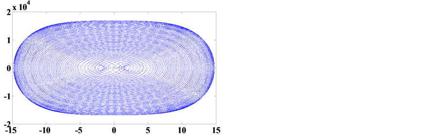
The phase portraits of Table 1 for Example 1 are shown in Figure 2. They are all chaotic. In order to prove the phase portraits to be chaotic, the (16) is transformed into three dimension autonomous Equation (29). The associated initial conditions are shown in (30). The Jacobi method is adopted, three Lyapunov Exponents LE = k are calculated and are listed in Table1 Then the results k is one positive, one negative and one zero, it conforms to the typical conclusion of chaos.

Table 1.
The main harmonic solutions and Lyapunov Exponent LE of the Example 1 under various
iF, when the initial value![]() .
.
 (a)
(a) 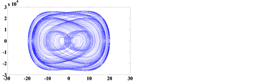 (b)
(b) 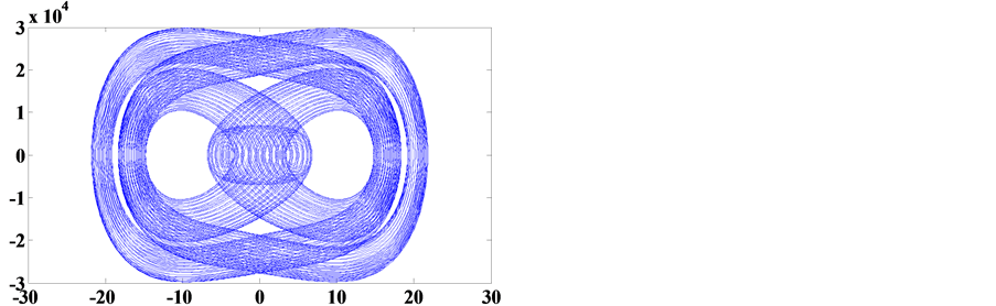 (c)
Table 1(c)
(c)
Table 1(c)
 (d)
Table 1(d)
(d)
Table 1(d)
Figure 2. Phase portraits of Table 1 abscissa denotes u and ordinate denotes ud = du/dt.
 (29)
(29)
 (30)
(30)
5.3. Two Method Mutually Verify the Correctness of Result
Two programs (power.nb and harmo.nb) obtain identical data in
Table1 Two programs show that the active power of self-excited and forced
oscillation components identically equal to zero under various situations. They
obey simultaneously the balance of reactive power. For the forced component, the
initial phase angle
 is determined when current source
 is connected to the circuit in the first instant. Although the
 is an arbitrary value, the included angle between phasors
 and
and
![]() always identically equal
always identically equal . Active power injected to the loop
 is equal to zero always.
The reactive power of each harmonic is individually conservation and mutual coupling.
The reactive power
 of forced component sent out by the excited source is equal to the reactive power
consumed by admittance with same frequency in (28), where the
of forced component sent out by the excited source is equal to the reactive power
consumed by admittance with same frequency in (28), where the
![]() is related to the self-oscillation amplitude
is related to the self-oscillation amplitude . On the other hand, the
 in (27) is determined according to the reactive power balance of self-oscillation
component, where the
in (27) is determined according to the reactive power balance of self-oscillation
component, where the
![]() is related to the forced voltage
is related to the forced voltage
![]() as shown in (15). The reactive power of self-oscillation component can’t be replenished
by excited source. The reactive power consumed by the
parallel loop
as shown in (15). The reactive power of self-oscillation component can’t be replenished
by excited source. The reactive power consumed by the
parallel loop
 must be balanced by itself.
5.4. Change of Initial Values Results in the Change of Main Harmonic Solution and Phase Portrait
 (31)
(31)
Under initial zero-state condition , when the
 and
and
 is not too different the (31) can be derived from the (20). The (31) shows there
is no more difference between
is not too different the (31) can be derived from the (20). The (31) shows there
is no more difference between
 and
and
![]() in Table1 Neither of them will be overwhelmed.
Therefore, it’s impossible to produce periodic oscillation. They generally produces
non-periodic chaos [18]
-[20] .
in Table1 Neither of them will be overwhelmed.
Therefore, it’s impossible to produce periodic oscillation. They generally produces
non-periodic chaos [18]
-[20] .
The intensity of self-oscillation is decided by the energy obtained at initial instant,
non-zero-input value relating to the initial phase angle
 which depends on the first instant of connecting current source. Owing to the different
 , it will make the changes of main harmonic solutions and chaotic
phase portrait as well. Refer to Table 1(c) and
Table 1(d), on condition that current amplitude
, it will make the changes of main harmonic solutions and chaotic
phase portrait as well. Refer to Table 1(c) and
Table 1(d), on condition that current amplitude
 is the same, only
 is different, the main harmonic solutions and phase portrait 2 (c) and (d) are different
as well.
is different, the main harmonic solutions and phase portrait 2 (c) and (d) are different
as well.
5.5. The Exclusive Circuit with Typical Significance
The lossless circuit proposed differs from any chaotic circuit in the academic field today. Its important contributions on theory are many aspects. The study of chaos produced by lossless circuit is still a vacancy at home and abroad [18] -[20] .
1) The scientific significance of the circuit is to promote the theory of Hamilton
equation. The conservative circuit consists of
capacitor and inductor in parallel. Suppose
 represents the total stored energy in conservative circuit for arbitrary instant
t. The
represents the total stored energy in conservative circuit for arbitrary instant
t. The
 represents the total stored energy obtained in the first instant
![]() , named Hamiltonian function. The T represents excited
periodic, and n is an arbitrary positive integer. Thus, for conservative circuit
without excitation source, we have (32). While lossless circuit with excitation
source, we have (33).
, named Hamiltonian function. The T represents excited
periodic, and n is an arbitrary positive integer. Thus, for conservative circuit
without excitation source, we have (32). While lossless circuit with excitation
source, we have (33).
 (32)
(32)
 (33)
(33)
The Figure 2 is a phase portraits of steady-state, there is no transient process for the lossless system. The circuit will enter immediately steady-state oscillation in the first instant when excitation source switches on.
2) When the initial values change, the steady orbit of the limit cycle won’t change. Moreover, the phase points will return to a fixed orbit automatically if interfered by external random factors. Therefore, the limit cycle is an attractor. For the Figure 1, chaotic oscillations have not attractiveness for adjacent trajectories. It is a nonlinear bounded function but not an attractor. Hamiltonian cycle is a periodic orbit rather than an attractor. For the lossless system, the main harmonic solution and phase portrait will change with the variation of initial values. It follows that the chaotic trajectories will change if interfered by external random factors. It proves that the (16) is locally unstable and cannot attract adjacent trajectories. Thus it is not an attractor. Moreover it also reveals the difference between the attractiveness and boundedness for chaos
6. Numerical Simulation Solutions Approached by Main Harmonic Solutions
6.1. Differences between the Linear and Nonlinear Equation Solutions
 (34)
(34)
 (35)
(35)
There is only one factor
 causing nonlinearity in (16) of Example 1, This is the key to cause the chaos. If
setting
causing nonlinearity in (16) of Example 1, This is the key to cause the chaos. If
setting , the Figure 1
becomes a periodic oscillation of linear circuit. We select the parameters of Table 1(a), obtains the linear equation shown
in (34). It is a periodic solution as shown in (35) with common fundamental frequency
, the Figure 1
becomes a periodic oscillation of linear circuit. We select the parameters of Table 1(a), obtains the linear equation shown
in (34). It is a periodic solution as shown in (35) with common fundamental frequency .
.
We draw the phase portrait of the (34) as shown in Figure 3, we can discover that there is no transient process for the lossless system. The trajectories show endless repetition after the beginning first instant of simulation. No matter how short the simulation step is, or how long the simulation time is, its trajectories show infinite repetition being a closed periodic orbit.
If
 starts from zero gradual increase, it can be found that the quantity of the circular
trajectories in the phase plane increases progressively as well, the greater
starts from zero gradual increase, it can be found that the quantity of the circular
trajectories in the phase plane increases progressively as well, the greater , the more circular trajectories. It shows the
evolutionary process
from periodic state to chaos. It is similar to the process from
period-doubling leading to chaos. It profoundly shows that the chaos is
the infinite or sufficient extension of oscillating period. It can be concluded
as follows: if equations generally include nonlinearity term
, the more circular trajectories. It shows the
evolutionary process
from periodic state to chaos. It is similar to the process from
period-doubling leading to chaos. It profoundly shows that the chaos is
the infinite or sufficient extension of oscillating period. It can be concluded
as follows: if equations generally include nonlinearity term , its solutions should be chaotic. That is a universal
form of the solutions of nonlinear oscillation equations. The solution is periodic
when taking the special circumstances of linearity. Hence, it proves that the nonlinearity
and chaos are universal while linearity and period are special.
, its solutions should be chaotic. That is a universal
form of the solutions of nonlinear oscillation equations. The solution is periodic
when taking the special circumstances of linearity. Hence, it proves that the nonlinearity
and chaos are universal while linearity and period are special.
6.2. Main Harmonic Balance Equation Belong to Linear Equation
Taking Table 1(a) as an example, the main harmonic balance Equation (25) is listed through Program Linear.nb by means of converse thinking. We obtain the (36) which is concrete form of the (25).
 (36)
(36)
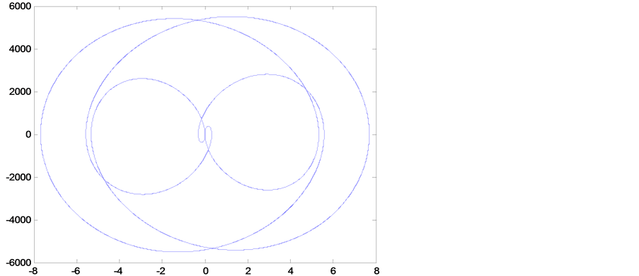
Figure 3. Phase portrait of the Equation (34).
The main harmonic equilibrium
Equation (36) is a linear equation which is from the data in
Table 1(a). Its solution is based on the linear theory. The main harmonic
solution shown in Table 1(a) can be obtained. The
(36) listed by means of converse thinking can show the solution of the linear equation
has to be a periodic function. In accordance with the calculation in (36), if taking , the common fundamental frequency is
 .
.
We draw the phase portrait of the (36). The Figure 4 shows that the phase plane is full filled by infinite infinitude trajectories. In addition, they have not completed a cycle within the simulation interval. The (34) and (36) are all linear equations which have fixed periodic solutions. However, the extraordinary difference of common fundamental frequency can reach 100 × 104 times. Comparing phase portrait Figure 3 with Figure 4, we can find extraordinary differences between them as well. But comparing phase portrait Figure 4 with Figure 2(a) is quite close.
6.3. Power Balance Theorem of Frequency Domain Is Further Extension of Tellegen’s Theorem
1) On the one hand, it proves that each harmonic component must obey various balance
law in the nonlinear network; on the other hand, it obtains the nonlinear coupling
relation among various harmonic component. Obviously, the frequency domain solutions
of nonlinear differential equations include lots of harmonic components. The main
harmonic is the main basic part of those harmonics. The great contribution of power
balance theorem is not only confined to obtain the main harmonic solutions itself.
Furthermore, it shows that main harmonic solution represents the main basic part
of the
periodic as well as chaotic solutions. They have become indispensable major
emphasis in this paper. The maximum value on the abscissa and ordinate of the Figure 2 are denoted as
 and
and . We can find quite approximate between
 and
and
 in the Table1 It is shown that the main harmonic
solutions are the fundamental part of approximate solution of the original Equation
(16), approximation to the extent of identical order of magnitude. The approximation
of phase portrait Figure 4 and
Figure 2(a) strongly proves the important worth to obtain the main harmonic
solution. The dense trajectories of two phase portraits have covered the entire
phase plane. It is unable to distinguish whether the simulating phase portraits
have already drawn a complete period or not. The Figure
2(a) contains many harmonic components, while the Figure
4 is the main components among them. It approximates to the solution
of original equation.
in the Table1 It is shown that the main harmonic
solutions are the fundamental part of approximate solution of the original Equation
(16), approximation to the extent of identical order of magnitude. The approximation
of phase portrait Figure 4 and
Figure 2(a) strongly proves the important worth to obtain the main harmonic
solution. The dense trajectories of two phase portraits have covered the entire
phase plane. It is unable to distinguish whether the simulating phase portraits
have already drawn a complete period or not. The Figure
2(a) contains many harmonic components, while the Figure
4 is the main components among them. It approximates to the solution
of original equation.
2) Finding the main basic part cannot rely on the mathematical transformation formula,
only can rely on the power equilibrium theorem to estimate the harmonic terms involving
in balance. It is a kind of mathematical physics method. For instance, as for the
superhet receiver circuit, we have to pre-estimate the three main harmonic components
involving in balance (two signal frequency ,
,
 and a difference frequency
 ).
).

Figure 4. Phase portrait of the Equation (36).
The approximate proper results can be obtained by the harmonic analysis. But it cannot be achieved by any mathematical transformation formula. The study explains the importance to rely on physical background. The transcendental selection of some components is used to satisfy the equation balance. If the true main harmonic component contained in the original equation is consistent with the selected component, we can obtain reasonable real domain solutions by program calculation. It follows that the selection is successful. Supposing the harmonic component selection is not accurate, it is impossible to get the correct results through program calculation. For example, we suppose that the harmonic solutions only contain forced component, and ignore (or don’t know) the self-oscillation component in equation. Obviously, a wrong conclusion will be obtained. With the support of correct physical background, we can correctly deduce the harmonic components involving in balance.
7. Conclusions
1) The phase portraits drawn by numerical simulation of Matlab are all periodic
functions with sufficientlylong period T. Their discrete spectra are very dense.
The non-periodicity of chaotic phase portrait refers to that there is no enough
time to draw a completely periodic phase portrait due to the simulating time Ts
< T. Therefore, it shows non-periodical on the phase plane. Only the simulating
observation time Ts is defined, then the numerical simulation phase portrait
can be defined as periodic or non-periodic. When the oscillation frequency is very
low, the spectrum is so dense and nearly continuous that almost no gap exists among
the
spectral lines. For example, the frequency of a periodic function is , period T = 109 second = 31.7
years. At present, the chaotic phase portrait is numerically simulated by Matlab.
According to the strict analysis of mathematical theory, the non-periodicity will
appear only if the irrational numbers are introduced in the calculation. Matlab
uses approximating rational numbers to replace irrational numbers. Therefore, it
can be valid always that there is a sufficient small fundamental frequency
, period T = 109 second = 31.7
years. At present, the chaotic phase portrait is numerically simulated by Matlab.
According to the strict analysis of mathematical theory, the non-periodicity will
appear only if the irrational numbers are introduced in the calculation. Matlab
uses approximating rational numbers to replace irrational numbers. Therefore, it
can be valid always that there is a sufficient small fundamental frequency , and the all harmonic frequency are equal to
integral multiple of
, and the all harmonic frequency are equal to
integral multiple of . For example
 . When simulating time Ts < T the
phase portrait drawn is a non-periodic function.
. When simulating time Ts < T the
phase portrait drawn is a non-periodic function.
The phase portrait in Figure 4 certainly is periodic functions with extremely low frequency. However the trajectories fully fill whole phase plane. It cannot be almost distinguished from chaotic phase portrait.
2) The chaotic solution of the equation is judged with a positive Lyapunov Exponent k > 0. However, the software can only deal with rational numbers as well. When the operation time interval Td > T the phase portrait is a periodic function. If the operation time interval Td < T, the variable u is a non-periodic function within the interval Td. Therefore, a Lyapunov Exponent k > 0 is obtained, and we can judge the solution is chaos. Generally speaking, Td and Ts are much less than T.
3) If the time domain solution of differential equations can’t be obtained, it’s
impossible to get the adequate representative part of the time function. However,
finding harmonic solutions of frequency domain possesses unique advantages. Although
it is unable to obtain all harmonic terms of Fourier series, the main representative
part can still be obtained. The power balance theorem provides sufficient theoretical
basis for harmonic analysis method. It is a feasible way to handle the nonlinear
oscillating equations with difficulties to find its solution. The (36) is the main
harmonic component of the original equation. The (34) is the linear part of the
original equation. The
 of those two equations differs more than one million times. The comparison between
the main harmonic component and linear part proves the rationality and correctness
of former. Currently, this kind of analysis method is still a vacancy at home and
abroad.
of those two equations differs more than one million times. The comparison between
the main harmonic component and linear part proves the rationality and correctness
of former. Currently, this kind of analysis method is still a vacancy at home and
abroad.
4) The study mainly focuses on the analysis of the reactive power equilibrium. It makes important contribution to obtain the solution. The reactive power is a rare academic term on the field of primary electronic science and technology. The study introduces the concept to promote the development of the basic theory of electronic science.
Acknowledgements
The study was supported by National Natural Science Foundation of China (No. 60662001).
References
- Huang, B.H., Song, C.N. and Huang, H.Q. (2003) Research & Progress of Solid State Electronics, 23, 57-62.
- Huang, B.H., Huang, X.M. and Li, S.Z. (2003) Journal of Circuit and Systems, 8.
- Huang, B.H., Huang, X.M. and Zhang, H.M. (2005) Research & Progress of Solid State Electronics, 25, 102-107.
- Huang, B.H., Huang, X.M. and Zhang, C. (2006) Journal of University of Electronic Science and Technology of China, 35.
- Huang, B.H., Huang, X.M. and Wang, Q.H. (2006) Research & Progress of Solid State Electronics, 26, 43-48.
- Huang, B.H. and Kuang, Y.M. (2007) Journal of Guangxi University (Natural Science Edition), 32.
- Kuang, Y.M. and Huang, B.H. (2008) Journal of Guilin University of Technology (Natural Science Edition), 28.
- Huang, B.H., Niu, L.R., Lin, L.F. and Sun, C.M. (2007) Acta Electronica Sinica, 35, 1994-1998.
- Huang, B.H., Huang, X.M. and Wei, S.G. (2008) Journal on Communications, 29, 65-70.
- Huang, B.H., Chen, C., Wei, S.G. and Li, B. (2008) Research & Progress of Solid State Electronics, 28, 57-62.
- Huang, B.H., Huang, X.M. and Li, H. (2011) Main Components of Harmonic Solutions. International Conference on Electric Information and Control Engineering, New York, 15-17 April 2011, 2307-2310.
- Huang, B.H., Huang, X.M. and Li, H. (2011) Procedia Engineering, 16, 325-332. http://dx.doi.org/10.1016/j.proeng.2011.08.1091
- Huang, B.H., Yang, G.S., Wei, Y.F. and Huang, Y. (2013) Applied Mechanics and Materials, 325-326, 1508-1514. (EI No.: 20132916506624)
- Huang, B.H., Yang, G.S., Wei, Y.F. and Huang, Y. (2013) Applied Mechanics and Materials, 327, 1508-1514. (EI No.: 20132716474771)
- Feng, J.C. and Li, G.M. (2012) Journal of South China University of Technology (Natural Science Edition), 40, 13-18.
- Mickens, R.E. (1984) Journal of Sound Vibration, 94, 456-460. http://dx.doi.org/10.1016/S0022-460X(84)80025-5
- Ganji, D.D., Esmaeilpour, M. and Soleimani, S. (2010) Computer Mathematics, 87, 2014-2023.
- Huang, B.H., Li, G.M. and Wei, Y.F. (2012) Modern Physics, 2, 60-69.
- Huang, B.H., Li, G.M. and Liu, H.J. (2013) Modern Physics, 3, 1-8. http://dx.doi.org/10.12677/MP.2013.31001
- Chen, Y.M. and Liu, J.K. (2007) Physics Letters A, 368, 371-378. http://dx.doi.org/10.1016/j.physleta.2007.04.025
Supplementary
Mathematica Program (These are listed below in the order of appearance): 1) Twoωhp.nb; 2) Leq.nb; 3) Power.nb; 4) ignore.nb; 5) whwh.nb; 6) harmo.nb; 7) Linear.nb.