Journal of Modern Physics
Vol. 2 No. 10 (2011) , Article ID: 8052 , 5 pages DOI:10.4236/jmp.2011.210141
Structure Transformations in the Polycrystalline (Ti,Nb)3Al Alloy under Shock-Wave Loading
1Institute of Metal Physics, Ural Division of Russian Academy of Sciences, Ekaterinburg, Russia
2Academician E. I. Zababakhin Russian Research Institute of Technical Physics, Russian Federal Nuclear Center, Snezhinsk, Russia
E-mail: kazantseva@imp.uran.ru
Received June 28, 2011; revised August 1, 2011; accepted August 13, 2011
Keywords: Ti3Al, Phase Transformation, Shock Waves
ABSTRACT
Structure transformations in the two-phase (Ti, Nb)3Al alloy, induced by shock-wave loading, were studied. The samples were subjected to an impact of a steel plate. The maximum pressure on the samples’ surfaces was 100 GPa, while the maximum temperature was 573 K. The b0 ® a2 phase transformation occurred during strong deformations. High temperature rectilinear dislocations (such types of dislocations usually could arise at 1073 K) with the c-component, which occasionally formed slip bands, were located at the a2-phase grains after the shock. The deformation a2-phase twins were not observed.
1. Introduction
Shock waves in materials produce unusually great numbers of the dislocations that substantially change mechanical properties of metals, such as the strength, plasticity, resistance to damage, or cracking [1-3]. Stresses arising in materials may be relaxed because of the rearrangements of the dislocations to configurations with more favorable energy, twinning, or phase transformations. Plate impact is considered as the standard diagnostic means to characterize the dynamic response of the materials. These experiments are very important for the structural materials. In particular, the developments of jet turbine engines require knowledge of the materials’ responses to impact events, such as the bird strikes, damages by foreign objects, and blade containments. Ti3Albase alloys are an interesting subject for studying. Excellent elevated-temperature properties and low density make the titanium aluminides attractive candidates for both engine and airframe applications, particularly in the aerospace industry. However, poor ductility and low fracture toughness have been the key limiting factors in utilizing the alloys.
Absence of the deformation twinning has frequently been referred to as one of the reasons for the brittleness of Ti3Al, especially in its polycrystalline form [4]. This is also the case when Ti3Al is deformed at high-strain rates, such as those achieved by shock loading [5]. The shockwave loading in [5] was done by the technique of the plate impact; the maximum pressure on the samples’ surfaces was 12 GPa. Brief information on the phase transformations in Ti3Al-base alloy under shock-wave loading was given in [6].
It is assumed that the twinning process is independent of temperature and is governed by only the applied stress. This process is considerably facilitated in crystals with defects that serve as stress concentrators, as well as by alloying that leads to changes in the stacking-fault formation energy. In [7] it is found that the deformation twinning occurs only in the Ti-36.5 at%Al single crystals under specific conditions (i.e., off-stoichiometric compositions, high temperatures, and if the compression axis is close to the c-axis). In [8] the authors have suggested the occurrence of the deformation twinning in Ti3Al grains coexisting with grains having the B2 superstructure in Ti-24 at%-11 at%Nb alloys.
The purpose of this work is a detailed study of the deformation behavior of the two-phase polycrystalline (Ti, Nb)3Al alloy under the shock-wave loading with a maximum pressure of 100 GPa on the samples’ surfaces.
2. Materials and Methods
The subjects of this study, the (Ti, Nb)3Al polycrystals, were smelted from titanium iodide (99.95%), extra-pure aluminum (99.9%), and niobium (99.9%) in an argon atmosphere in an arc furnace (Table 1). The ingots were homogenized at 1400˚C for 5 h in a helium atmosphere. For our study, the samples were cut to sizes of 10 ´ 10 ´ 10 mm from the ingots and placed on a steel plate; the loading was done with another steel plate. Shock-wave loading of the samples was done at the Academician E. I. Zababakhin Russian Research Institute of Technical Physics, Russian Federal Nuclear Center, Snezhinsk, Russia. The samples were exposed to an impact of the steel plate, and the maximum presure on the samples’ surfaces was 100 GPa, while the pulse duration was 1 ms. We used a chamber for saving samples after the shockwave loading. The X-ray diffraction analysis was performed using a DRON-3 diffractometer with the Co ka and Cu ka radiation. The TEM analysis was performed with a JEM-200CX transmission electron microscope.
3. Results and Discussion
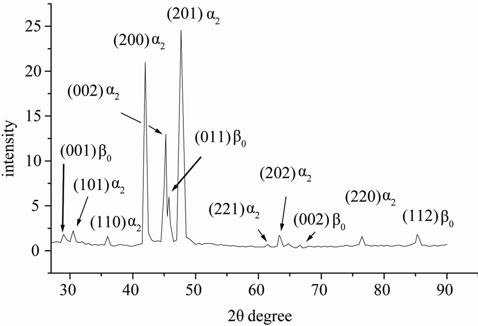
The X-ray pattern of the initial sample is shown in Figure 1(a). The phase composition of the initial sample had two components: a2 (Ti3Al, P63/mmc, DO19) and b0 (TiAl, Pm3m, B2). The lattice parameters of the phases in the initial state are given in Table 2.
The results of the X-ray analysis of the sample after the shock-wave loading showed that the intensity of the b0-phase lines was severely reduced; the lines at intermediate angles disappeared (Figure 1(b)). The lattice parameters of the b0-phase could not be accurately determined; however, those of the a2-phase changed to а = 0.5774 nm; с = 0.4663 nm.
According to our optical study, in its initial state, the alloy included two species of grains, on average 20 mm in size (Figure 2(a)), whereas after the shock loading, the grains were fragmented (Figure 2(b)). Results of the micro-hardness measurements are presented in Figure 3.
The hardness of the sample increased after the shockwave loading, the maximum hardness was observed at the edge of the sample.

Table 1. Chemical composition of the initial samples (weight %).
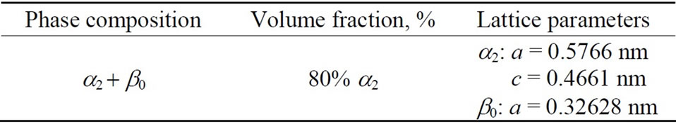
Table 2. Phase composition of the samples in the initial state.
 (a)
(a)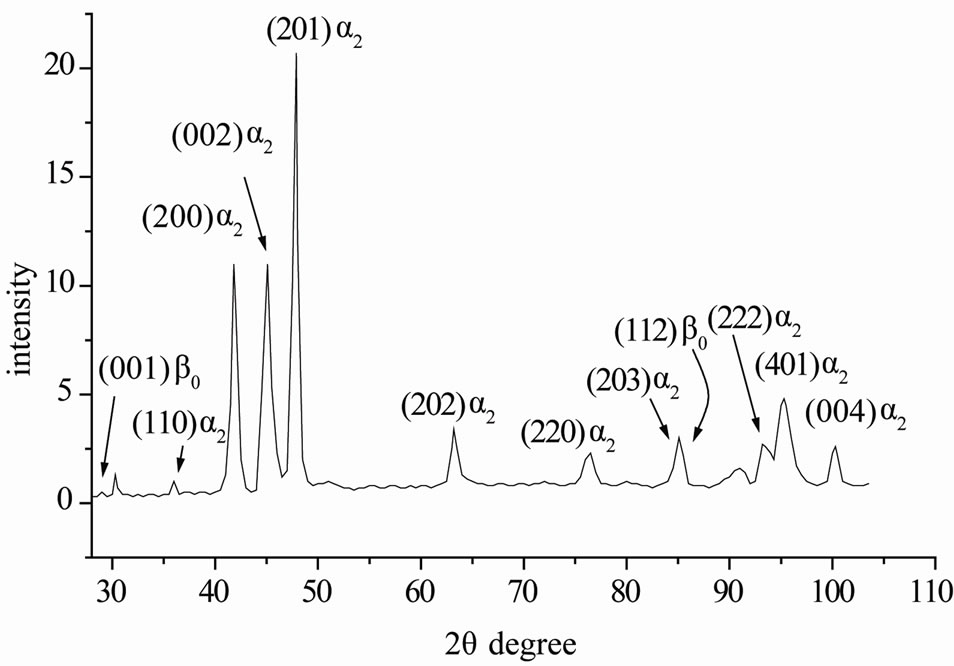 (b)
(b)
Figure 1. Results of the X-ray analysis of the (Ti, Nb)3Al alloy: (a) the initial state; (b) the state after the shock loading.
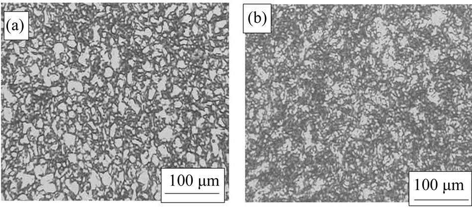
Figure 2. The microstructure of the (Ti, Nb)3Al alloy, optical microscopy, polarized light: (a) the initial state; (b) the state after the shock loading.
Our TEM study of the sample in its initial state showed the structure with the a2-phase and b0-phase grains, as well as the grains with plates of the a2 phase piercing throughout the b0-phase grains. Single a2-phase grains were much coarser than the two-phase grains (Figure 4).
The TEM study of the sample after the shock-wave loading revealed the rectilinear dislocations inside the a2
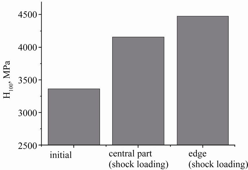
Figure 3. Results of the micro-hardness measurements.
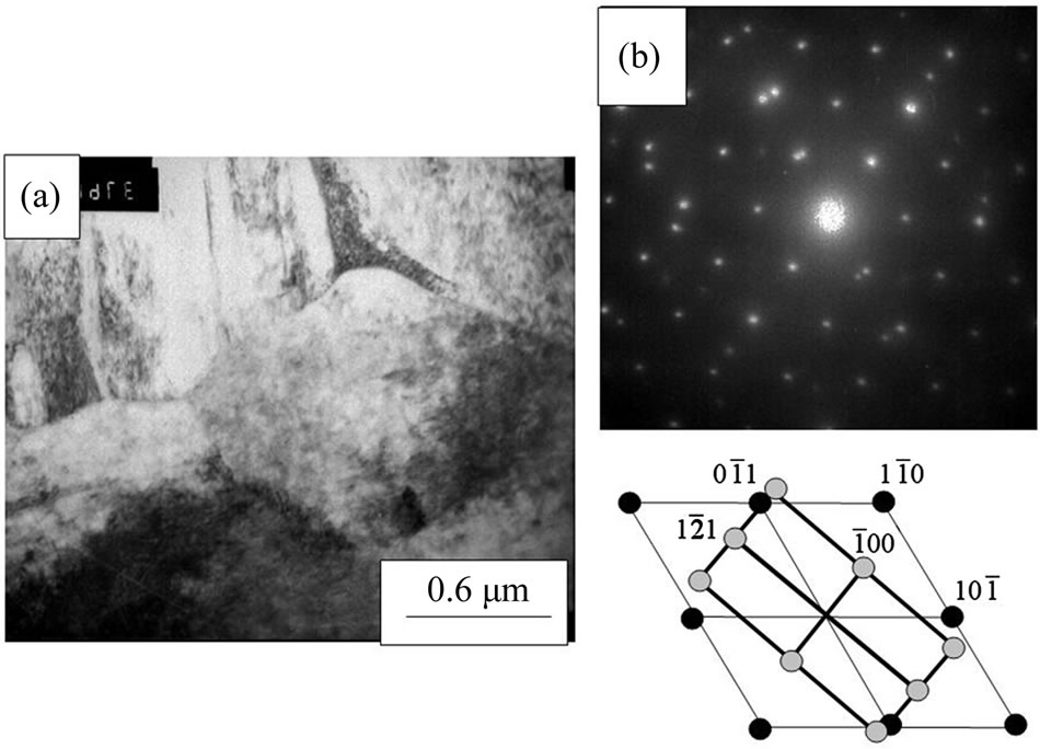
Figure 4. The microstructure of the (Ti, Nb)3Al alloy in the initial state, TEM: (a) bright field image; (b) diffraction pattern to a); zone axis [111] b0 II [012]a2.
grains. Figure 5 shows the dislocation systems; we found that they are c-component dislocations, because they are clearly seen in reflection g = 0002 (Figure 5(a), (b)). For the dislocations in Figures 5(c), (d), the condition gb = 0 is fulfilled in reflection g = .
.
It is known that the slip on 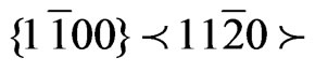 (prism a-slip),
 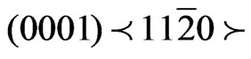 (basal a-slip),
 (type-I pyramidal 2c + a-slip) and
  (type-II pyramidal 2c + a-slip) are the operative slip systems in Ti3Al, among which the prism slip is the most-readily operative one because of a considerably lower critical resolved shear stress [9].
In the Ti3Al alloy, during the deformation by compression at the room temperature, along with the main slip system , the slip system
 contributes to the deformation. In the latter slip system, the edge dislocations are less mobile.
As the temperature increases (to 923 K), the slip morphology changes, such that the dislocations are localized in the slip bands and split according to the reaction [10]:
1/3 < > ® 1/6 <
 > + APB +1/6 <
 >.
>.
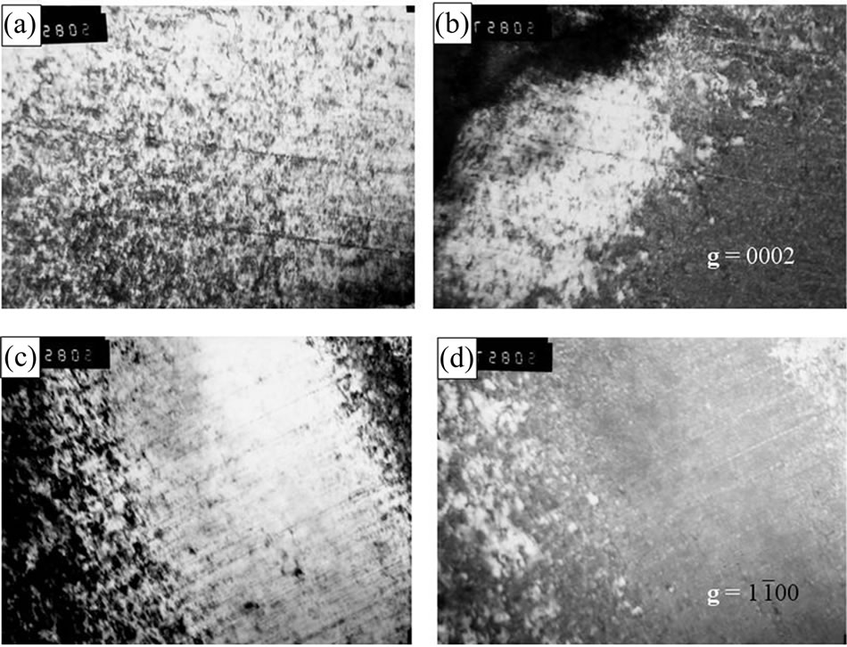
Figure 5. Dislocations in the (Ti, Nb)3Al alloy after the shock loading: (a) bright-field image to (b), (b) dark-field image in g = 0002; (c) bright-field image to (d), (d) darkfield image in g = .
.
According to [9], a similar dislocation picture with the c-component dislocations, as in our case, is observed in the range of the thermal strengthening for Ti3Al crystal (~1073 K) and during the deformation at the room temperature. In our experiment, the maximum temperature on the samples’ surfaces was 573 K.
We also found the band structure resembling the twin inside the a2-grains (Figure 6); however, in reality it is not a twin. The diffraction pattern taken from the region with the band structure did not have the reflections of the b0 phase. The b0 reflections must appear according to the orientation relationship between the crystal lattice of the a2- and b0-phases: (0001)a2 || (110)b0; < >a2 || <
 >b0.
>b0.
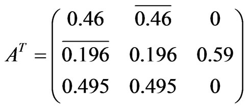
The presence of certain orientation relationships between the lattices of the different phases allows one to precisely identify (within a single grain) the selected-area electron-diffraction (SAED) patterns obtained from different sites of the same grain. For indexing the diffraction patterns, we calculated the matrices of the correspondence between the planes and zone axes of the crystal lattices of the a2- and b0-phases in our alloy. The calculation is based on the solution of the following ma-
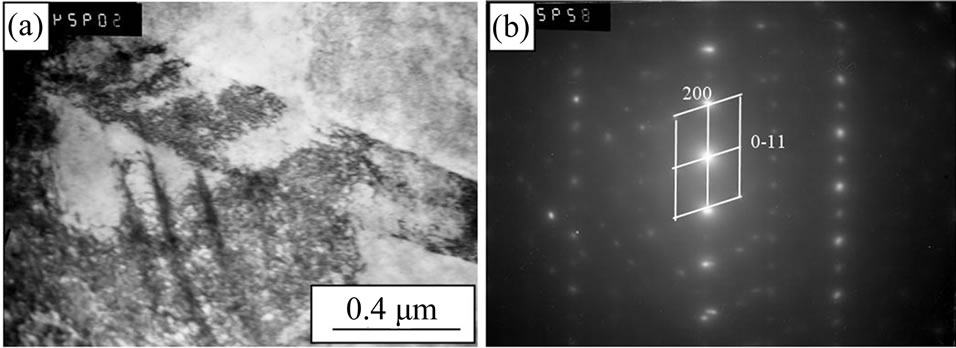
Figure 6. Band structure in a2-phase: (a) bright-field image, (b) diffraction pattern to (a), zone axis [011] a2.
trix equations that allow one to find the indices of the corresponding phases: Hb0 = A*Ha2; Ua2 = AT*Ub0, where H and U are the column vectors containing the indices of the planes and directions in the crystal lattices of the phases, respectively; A and AT are the transformation matrices for the determination of the planes and directions in these two lattices. With the lattice parameters of the phases presented in Table 2, the A and AT matrices in our alloy are calculated as:
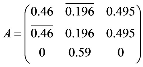 ,
,
We find that the band structure resembling twins is observed only in the a2 grains. We carefully checked the diffraction pattern taken from the place with the band structure and reflections of twins were not observed.
Our TEM study also showed that greater changes occurred in the b0-phase grains. In the initial state, the b0-phase was observed in the form of the grains or layers between the a2 plates. After the shock loading, the darkfield images showed this phase as fine particles (Figure 7).
Since alloys with this composition usually are severely deformed only at high temperatures owing to the roomtemperature brittleness, we compared the structures obtained here with those of a similar two-phase alloy after rolling at 1173 K [11].
The authors of [11] also observed the b0 ® a2 phase transformation during strong deformations and re-crysta-
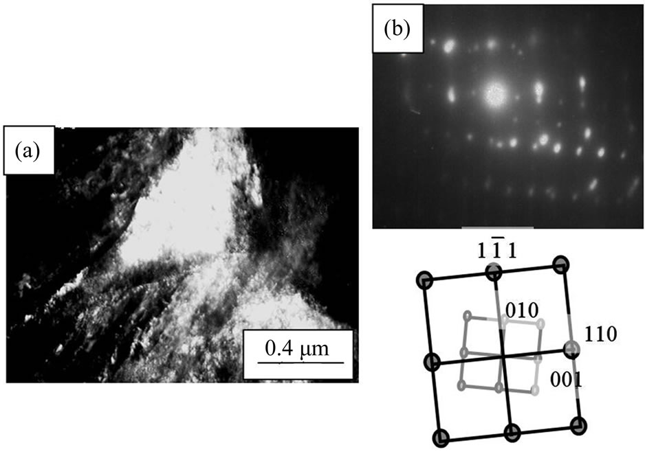
Figure 7. Microstructure of the (Ti, Nb)3Al alloy after shock loading, ТЕМ: (a) dark-field image in (110)B2; (b) diffraction pattern to (а), zone axis  b0 II [100]a2.
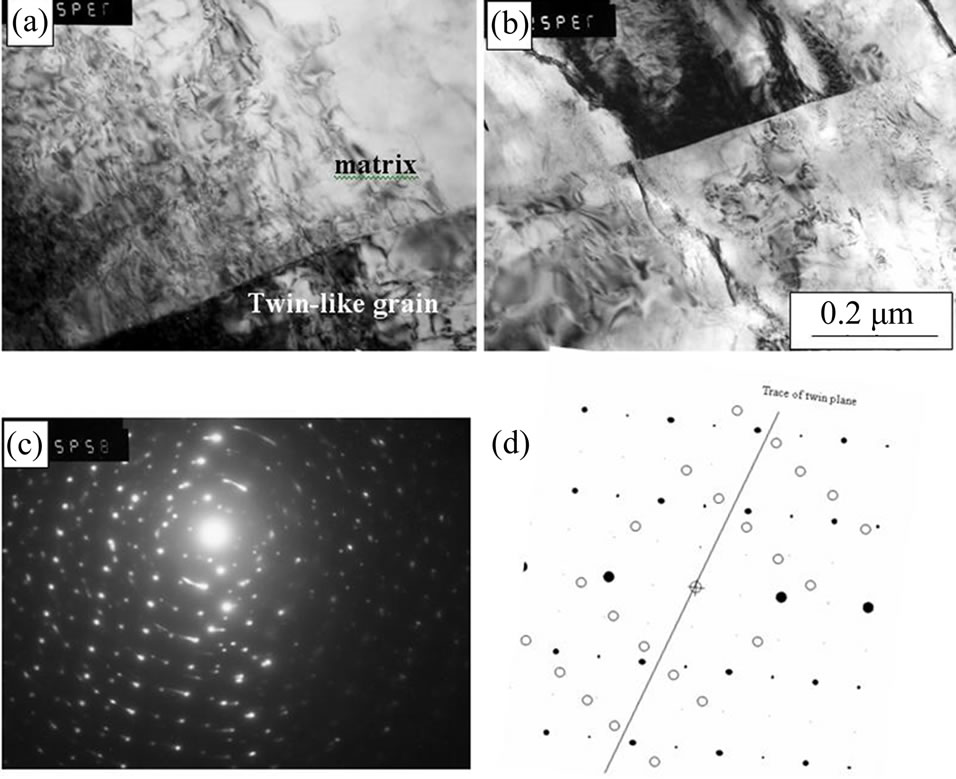
Figure 8. Twin-like a2 grains: (a) dark field image in twinlike reflex, (b) dark-field image in matrix reflex; (c) diffraction pattern to (a)-(b) zone axis [010]; (d) bright-field image, d-diffraction pattern to (d), zone axis [011].
llizations of both a2- and b0-phases during the cooling of the alloy. When the sample was deformed to 85 %, the b0 phase transformed fully to the a2 phase [11].
Figure 8 shows a structure that looks like a twin. The diffraction pattern shown in Figure 8(b) is quite similar to that reported for the {2 12  3}
3}  twin by Kishida et al. [7]. But in reality it is not a twin. We could not obtain the dark-field or bright-field images from this place to prove the formation of the twin. Probably, in this case, we found the grain boundary, that looks like a twin.
4. Conclusions
The structure of the two-phase (Ti, Nb)3Al polycrystal after the shock-wave loading has been studied in detail using the X-ray analysis, optical microscopy, and transmission electron microscopy. Our results can be summarized as follows.
1) Strong instantaneous (100 GPa, 1 ms) shock-wave loading of the two-phase (Ti, Nb)3Al alloy caused the phase transformations B2 ® DO19.
2) The rectilinear high temperature dislocations with the c-component formed the slip bands that were observed inside the a2 grains after the shock-wave loading.
3) No deformation twin was found in the a2 grains after the shock-wave loading.
5. Acknowledgements
This work was supported by the Russian Foundation for Basic Research (project no. 10-02-00354-а).
REFERENCES
- E. I. Zababakhin, “Some Problems of Explosion Gas Dynamics,” Russian Research Institute of Technical Physics—Russian Federal Nuclear Center, Snezhinsk, 1997, 207 Pages.
- Z. Q. Wang, I. J. Beyerlein and R. LeSar, “Dislocation Motion in High Strain-Rate Deformation,” Philosophical Magazine A, Vol. 87, No. 16-17, 2007, pp. 2263-2279. doi:10.1080/14786430601153422
- B. A. Remington, P. Allen, E. M. Bringa, J. Hawreliak, D. Ho, K. T. Lorenz, H. Lorenzana, J. M. Mc Naney, M. A. Meyers, S. W. Pollaine, K. Rosolankova, B. Sadik, M. S. Schneider, D. Swift, J. Wark and B. Yaakobi, “Material Dynamics under Extreme Conditions of Pressure and Strain Rate,” Materials Science and Technology, Vol. 22, No. 4, 2006, pp. 474-488. doi:10.1179/174328406X91069
- M. H Yoo, C. L. Fu and J. K. Lee, “Deformation Twinning in Metals and Ordered Intermetallics-Ti and TiAluminides,” Journal de Physique III, Vol. 1, 1991, pp. 1065-1067. doi:10.1051/jp3:1991172
- M. Ikebuchi, H. Inui, Y. Shirai, M. Yamaguchi, S. Fujita and T. Nishisako, “Microstructures of Some Intermetallic Compounds Deformed by Impact Loading,” Materials Science and Engineering, Vol. A192-193, 1995, pp. 289- 304. doi:10.1016/0921-5093(94)03237-8
- N. V. Kazantseva, B. A. Greenberg, A. A. Popov and E. V. Shorokhov, “Phase Transformations in Ni3Al, Ti3Al and Ti2AlNb Intermetallics under Shock-Wave Loading,” Journal de Physique IV France, Vol. 110, 2003, pp. 923- 928. doi:10.1051/jp4:20020812
- K. Kishida, Y. Takahama and H. Inui, “Deformation Twinning in Single Crystals of a D019 Compound with an Off-Stoichiometric Composition (Ti-36.5 at%Al),” Acta Materialia, Vol. 52, No. 16, 2004, pp. 4941-4952. doi:10.1016/j.actamat.2004.06.051
- M. A. Morris and D. G. Morris, “Strain Localization, Slip-Band Formation and Twinning Associated with Deformation of a Ti-24 at% Al-11 at% Nb Alloy,” Philosophical Magazine A, Vol. 63, 1991; pp. 1175-1178. doi:10.1080/01418619108205576
- L. E. Kar’kina and L. I. Yakovenkova, “Temperature Anomalies of Deformation Behavior and Dislocation Structure of Ti3Al: A Review,” Fizika Metallov i Metallovedenie, Vol. 108, No. 2, 2009, pp. 188-216. doi:10.1134/S0031918X09080110
- S. A. Court, J. P. A. Lofvander, M. H. Loretto and H. L. Fraser, “The Influence of Temperature and Alloying Additions on the Mechanisms of Plastic Deformation of Ti3Al,” Philosophical Magazine A, Vol. 61, No. 1, 1990, pp. 109-139. doi:10.1080/01418619008235561
- S. Suwas, R. K. Ray, A. K. Singh and S. Bhargava, “Evolution of Hot Rolling Textures in a Two-Phase (α2 + β) Ti3Al Base Alloy,” Acta Materialia, Vol. 47, No. 18, 1999, pp. 4585-4598. doi:10.1016/S1359-6454(99)00327-4